


STUDIOQUAD
Studio Quad
4 IN-4 OUT
Studio Effects Processor
A Harman International Company
1
2
FX Edit
Program
CompareCompare
4 IN 4 OUT MULTI-EFFECTS PROCESSOR
S-DISC
™
P
ROCESSING
1:Hall 2:Rm 3:Dly 4:Dtn
S-DISC
™
PROCESSING
Owner's Manual
IMPORTANT!
FOR YOUR PROTECTION, PLEASE READ THE FOLLOWING:
WATER AND MOISTURE: Appliance should not be used near water (e.g. near a
bathtub, washbowl, kitchen sink, laundry tub, in a wet basement, or near a swimming
pool, etc). Care should be taken so that objects do not fall and liquids are not spilled
into the enclosure through openings.
POWER SOURCES: The appliance should be connected to a power supply only of
the type described in the operating instructions or as marked on the appliance.
GROUNDING OR POLARIZATION: Precautions should be taken so that the ground-
ing or polarization means of an appliance is not defeated.
POWER CORD PROTECTION: Power supply cords should be routed so that they are
not likely to be walked on or pinched by items placed upon or against them, paying
particular attention to cords at plugs, convenience receptacles, and the point where
they exit from the appliance.
SERVICING: The user should not attempt to service the appliance beyond that
described in the operating instructions. All other servicing should be referred to quali-
fied service personnel.
FUSING: If your unit is equipped with a fuse receptacle, replace with only same type
fuse. Refer to replacement text on the unit for correct fuse type.
U.K. MAINS PLUG WARNING
A moulded mains plug that has been cut off from the cord is unsafe. Discard the
mains plug at a suitable disposal facility. NEVER UNDER ANY CIRCUM-
STANCES SHOULD YOU INSERT A DAMAGED OR CUT MAINS PLUG INTO
A 13 AMP POWER SOCKET. Do not use the mains plug without the fuse cover
in place. Replacement fuse covers can be obtained from your local retailer.
Replacement fuses are 13 amps and MUST be ASTA approved to BS1362.
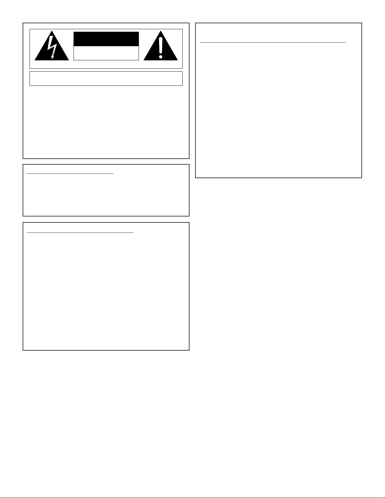
The symbols shown at left are internationally accepted symbols that warn of
potential hazards with electrical products. The lightning flash with arrowpoint in
an equilateral triangle means that there are dangerous voltages present within
the unit. The exclamation point in an equilateral triangle indicates that it is nec-
essary for the user to refer to the owner’s manual.
These symbols warn that there are no user serviceable parts inside the unit. Do
not open the unit. Do not attempt to service the unit yourself. Refer all servicing
to qualified personnel. Opening the chassis for any reason will void the manu-
facturer’s warranty. Do not get the unit wet. If liquid is spilled on the unit, shut it
off immediately and take it to a dealer for service. Disconnect the unit during
storms to prevent damage.
CAUTION
ATTENTION: RISQUE DE CHOC ELECTRIQUE - NE PAS OUVRIR
WARNING: TO REDUCE THE RISK OF FIRE OR ELECTRIC
SHOCK DO NOT EXPOSE THIS EQUIPMENT TO RAIN OR MOISTURE
RISK OF ELECTRIC SHOCK
DO NOT OPEN
LITHIUM BATTERY WARNING
CAUTION!
This product contains a lithium battery. There is danger of explosion if battery is
incorrectly replaced. Replace only with an Eveready CR 2032 or equivalent.
Make sure the battery is installed with the correct polarity. Discard used batter-
ies according to manufacturer’s instructions.
ADVARSEL!
Lithiumbatteri - Eksplosjonsfare. Ved utskifting benyttes kun batteri som anbefalt
av apparatfabrikanten. Brukt batteri returneres apparatleverandøren.
ADVARSEL!
Lithiumbatteri - Eksplosionsfare ved fejlagtig håndtering. Udskiftning må kun ske
med batteri av samme fabrikat og type. Levér det brugte batteri tilbage til
leverandøren.
VAROITUS!
Paristo voi räjähtää, jos se on virheellisesti asennettu. Vaihda paristo ainoastaan
laitevalmistajan suosittelemaan tyyppin. Hävitä käytetty paristo valmistajan ohjei-
den mukaisesti.
VARNING!
Explosionsfara vid felaktigt batteribyte. Använd samma batterityp eller en ekviva-
lent typ som rekommenderas av apparattillverkaren. Kassera använt batteri
enligt fabrikantens instruktion.

1
Table of Contents
Studio Quad Owner's Manual
Table Of Contents. . . . . . . . . . . . . . . . . . . . . . . . . . . . . . . . . 1
Introduction . . . . . . . . . . . . . . . . . . . . . . . . . . . . . . . . . . . . . 2
Warranty. . . . . . . . . . . . . . . . . . . . . . . . . . . . . . . . . . . . . . . . 2
SECTION 1 - SETTING UP
Unpacking the Studio Quad . . . . . . . . . . . . . . . . . . . . . . . . . 3
Suppling Power . . . . . . . . . . . . . . . . . . . . . . . . . . . . . . . . . . 3
Front Panel Controls . . . . . . . . . . . . . . . . . . . . . . . . . . . . . . . 4
Rear Panel Controls . . . . . . . . . . . . . . . . . . . . . . . . . . . . . . . 6
Making Connections . . . . . . . . . . . . . . . . . . . . . . . . . . . . . . . 7
A Word About Bypass . . . . . . . . . . . . . . . . . . . . . . . . . . . . . 9
SECTION 2 - BASIC FUNCTIONS OF THE STUDIO QUAD
Getting Around the Operating System. . . . . . . . . . . . . . . . . 10
Program Mode. . . . . . . . . . . . . . . . . . . . . . . . . . . . . . . . . 10
FX Edit Mode. . . . . . . . . . . . . . . . . . . . . . . . . . . . . . . . . . 10
Selecting FX Types and Defaults . . . . . . . . . . . . . . . . . 11
Modifying FX Module Parameters Example . . . . . . . . . 11
Input/Output Configurations . . . . . . . . . . . . . . . . . . . . . 12
Using Modifiers . . . . . . . . . . . . . . . . . . . . . . . . . . . . . . 13
Linking a Parameter to a Modifier. . . . . . . . . . . . . . . . . 14
Setting up an LFO or Dynamic . . . . . . . . . . . . . . . . . . . 15
Comparing Programs . . . . . . . . . . . . . . . . . . . . . . . . . . . . . 16
Storing Programs . . . . . . . . . . . . . . . . . . . . . . . . . . . . . . . . 17
SECTION 3 - EFFECTS AND PARAMETERS
About Modules and the Effect Charts . . . . . . . . . . . . . . . . . 18
About the Charts. . . . . . . . . . . . . . . . . . . . . . . . . . . . . . . . . 19
Reverbs . . . . . . . . . . . . . . . . . . . . . . . . . . . . . . . . . . . . . . 19
Chorus and Flange . . . . . . . . . . . . . . . . . . . . . . . . . . . . . . 22
Phasers . . . . . . . . . . . . . . . . . . . . . . . . . . . . . . . . . . . . . . 25
Tremolos and Auto Panners . . . . . . . . . . . . . . . . . . . . . . . 26
Pitch Shifters and Detuners. . . . . . . . . . . . . . . . . . . . . . . . 26
Delays . . . . . . . . . . . . . . . . . . . . . . . . . . . . . . . . . . . . . . . 29
EQs . . . . . . . . . . . . . . . . . . . . . . . . . . . . . . . . . . . . . . . . . 30
Noise Gate . . . . . . . . . . . . . . . . . . . . . . . . . . . . . . . . . . . . 31
SECTION 4-IN LEVELS AND UTILITIES
Auto/Manual Input Leveling. . . . . . . . . . . . . . . . . . . . . . . . . 32
Utility . . . . . . . . . . . . . . . . . . . . . . . . . . . . . . . . . . . . . . . . . 33
Adjusting the Screen Contrast . . . . . . . . . . . . . . . . . . . . . 33
MIDI Channel . . . . . . . . . . . . . . . . . . . . . . . . . . . . . . . . . . 33
Program Map . . . . . . . . . . . . . . . . . . . . . . . . . . . . . . . . . . 34
System Exclusive device channel . . . . . . . . . . . . . . . . . . . 34
Program Dump . . . . . . . . . . . . . . . . . . . . . . . . . . . . . . . . . 35
System Exclusive Bulk Dump . . . . . . . . . . . . . . . . . . . . . . 36
System Dump . . . . . . . . . . . . . . . . . . . . . . . . . . . . . . . . . . 36
Program Autoload. . . . . . . . . . . . . . . . . . . . . . . . . . . . . . . 37
Factory Reset . . . . . . . . . . . . . . . . . . . . . . . . . . . . . . . . . . 38
SECTION 5- APPENDIX
MIDI Implementation Chart . . . . . . . . . . . . . . . . . . . . . . . . . 39
Effects and Defaults List . . . . . . . . . . . . . . . . . . . . . . . . . . . 40
Effect Configuration Chart. . . . . . . . . . . . . . . . . . . . . . . . . . 41
Factory Program List. . . . . . . . . . . . . . . . . . . . . . . . . . . . . . 42
Studio Quad Specifications. . . . . . . . . . . . . . . . . . . . . . . . . 43
User Notes . . . . . . . . . . . . . . . . . . . . . . . . . . . . . . . . . . . . . 44

2
Introduction and Warranty
Studio Quad Owner's Manual
INTRODUCTION
Congratulations, and thank you for your purchase of the DigiTech
Studio Quad.
The Studio Quad gives you four completely independent inputs and
outputs driven by proven S-DISC™ technology. The results are obvi-
ous: sparkling clean sound and endless combinations of effects and
signal path routings.
WARRANTY
1. The warranty registration card must be mailed within ten days
after purchase date to validate the warranty.
2. DigiTech warrants this product, when used solely within the U.S.,
to be free from defects in materials and workmanship under nor-
mal use and service.
3. DigiTech liability under this warranty is limited to repairing or
replacing defective materials that show evidence of defect, pro-
vided the product is returned to DigiTech WITH RETURN AUTHO-
RIZATION, where all parts and labor will be covered up to a peri-
od of one year. A Return Authorization number may be obtained
from DigiTech by telephone. The company shall not be liable for
any consequential damage as a result of the product’s use in any
circuit or assembly.
4. Proof-of-purchase is considered to be the burden of the consumer.
5. DigiTech reserves the right to make changes in design, make
additions to, or improvements to this product without incurring any
obligation to install the same on products previously manufactured.
6. The foregoing is in lieu of all other warranties, expressed or
implied, and DigiTech neither assumes nor authorizes any person
to assume for it any obligation or liability in connection with the sale
of this product. In no event shall DigiTech or its dealers be liable
for special or consequential damages or from any delay in the per-
formance of this warranty due to causes beyond their control.
DigiTech™, Studio Quad™, and S-DISC™ are registered trademarks
of DOD Electronics Corporation.
IMPORTANT! The information contained in this manual is subject to change at any time
without notification. Some information in this manual may also be inaccu-
rate due to undocumented changes in the product or operating system
since this version of the manual was completed. The information con-
tained in this version of the manual supersedes all previous versions.

3
Section 1 - Setting Up
Studio Quad Owner's Manual
SECTION 1 - SETTING UP
UNPACKING THE STUDIO QUAD
Your Studio Quad was carefully assembled and packaged at the factory.
Before you proceed any further, make sure the following items are included:
• (1) Owner's manual
• (1) DigiTech Studio Quad Studio Effects Processor
• (1) PS0920 power supply
• (4) Rack screws
• (1) DigiTech warranty card
Please save all packaging materials. They were designed to protect
the unit from damage during shipping. In the unlikely event that the unit
requires service, use only the factory supplied carton to return the unit.
SUPPLYING POWER
The Studio Quad, like any piece of computer hardware, is sensitive to
voltage drops, spikes and surges. Interference such as lightning or
power "brownouts" can seriously, and in extreme cases, permanently
damage the circuitry inside the unit. Here are a few tips that will help
you get the best possible performance out of your Studio Quad while
avoiding damage:
• Always make sure you have a "clean" power source for connect-
ing to the Studio Quad. This means that the AC power line you
connect to the Studio Quad should be as free from voltage fluc-
tuations and RF interference as possible. In recording environ-
ments, "clean" power is also important in preventing AC hum or
buzz from getting to tape.
• Use a good quality spike / surge suppressor . This is an inexpen-
sive solution to all but the most severe AC line conditions. A
good quality power strip can save you a lot of money in repair
bills because they prevent large spikes and surges from reach-
ing your equipment racks. Also in this category (but more expen-
sive) are rackmount power conditioners. Some of these, like the
DigiTech PLM-82, have retractable light tubes and RF filtering.
• Always make sure that your audio lines are as far as possible
from power cables. This will further prevent noise, hum, and
stray magnetic fields from entering your signal path. If audio and
power lines must run close to each other, try to avoid running
them parallel to one another.
Use only high-quality audio cables to connect devices to and
from the Studio Quad. Although they're more expensive, they
sound better, last longer, and are much less likely to pick up or
induce noise, interference, hum, or buzz into your system.
4
Section 1 - Setting Up
Studio Quad Owner's Manual
FRONT PANEL CONTROLS
The layout of the Studio Quad's front panel is simple and straightfor-
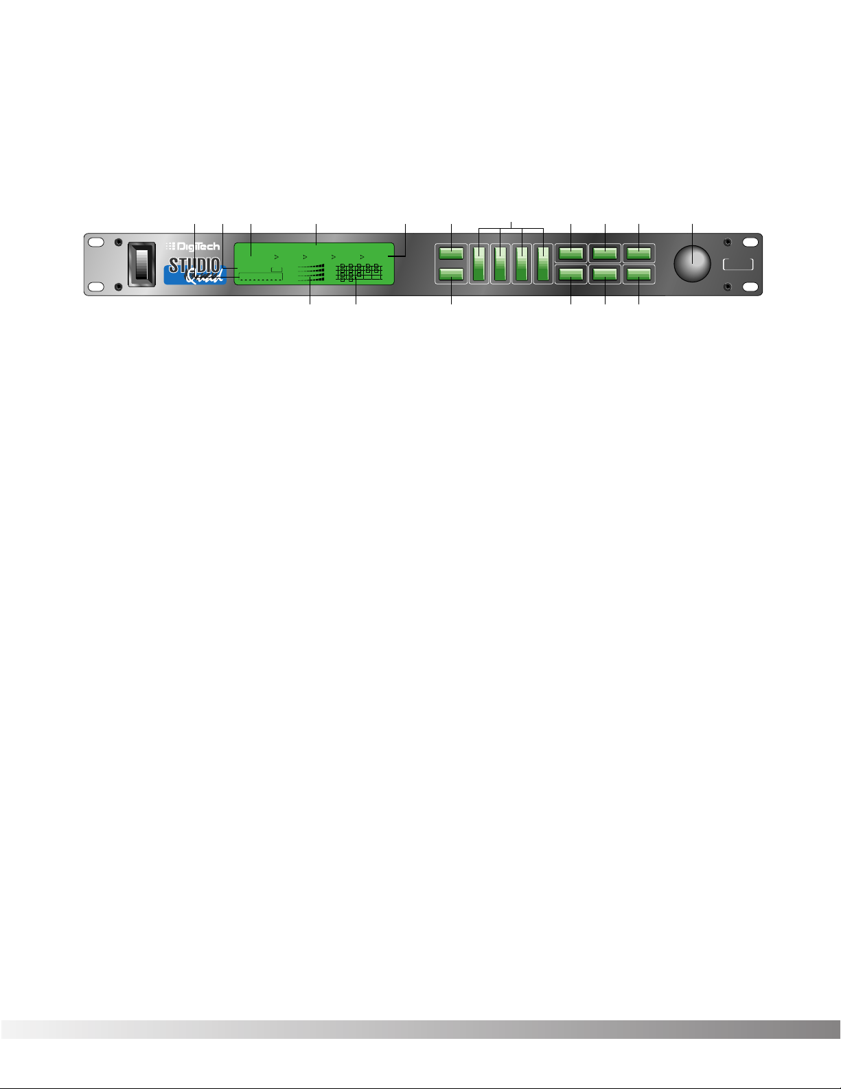
ward. Figure 1-1 shows the various parts of the Studio Quad.
Figure 1-1 Front Panel
1) DISPLAY - The Studio Quad's large custom display is where you
get most of the information you need to move around the operating
system. The display has several important sections that you need to
understand when you use the Studio Quad. They are:
1a) Program Number Indicator - These three large digits in the
upper left corner of the display indicate which Program is cur-
rently selected.
1b) Factory / User Indicators - Directly below the Program number
are the Factory and User Program indicators. These indicators
also include a CHANGED icon to tell you whether the Program
has been modified but not stored in memory. Factory Programs
can be modified but must be stored in a User Program location
since Factory Programs cannot be overwritten.
1c) Page Indicators - The bottom left corner of the display is
occupied by the Page indicators. They display the number of
Pages available and the Page which is currently selected.
These icons only appear in the FX Edit and Utilities modes.
1d) Information Line - This row of 24 characters (top line of the
display) is the Information line. It gives more detailed informa-
tion about specific functions and items, and contains things
like Program names, Parameter names, and Utility or auxiliary
information.
1e) Parameter Data Sections - There are four Parameter Data
sections in the display. They are immediately below the
Information line, and correspond with the <1>, <2>, <3>, and
<4> buttons on the front panel. Each section displays the cur-
rent value of the indicated Parameter. Each section also has
an arrow that shows which Parameter in the display is select-
ed.
*(24)5x8PixelCharacters*
IN 4
IN 3
IN 2
IN 1
%kHz
mSec
FACTORY PRG MODIFIED
MIDI
CHANGED
LEVEL 4
LEVEL 3
LEVEL 2
LEVEL 1
OUT 4
OUT 3
OUT 2
OUT 1
CLIP
CLIP
CLIP
CLIP
USER PRG MODIFIED
FX EDIT PAGE
12345678910
188
••8
%kHz
mSec
CHANGED
%kHz
mSec
CHANGED
%kHz
mSec
CHANGED
1
UTILITY PAGE
MODIFIERS
••8 ••8 ••8
2 3 4
Next Page
Utility
In Levels
Bypass
Prev Page
Store
1
234
FX Edit
Program
CompareCompareCompare
Auto LevelsAuto LevelsAuto Levels
4 IN 4 OUT MULTI-EFFECTS PROCESSOR
S-DISC
™
PROCESSING
1a 1d 1e1b1c 2 4 579 11
3
1f 1g 6810
S-DISC
™
PROCESSING

5
Section 1 - Setting Up
Studio Quad Owner's Manual
A CC indicator in each group tells whether the indicated
Parameter is set up to be continuously controlled ( "continuous
control" includes internal LFOs, dynamic modifiers, and MIDI
continuous controlller data). Directly below each section is a
CHANGED indicator that lights to indicate that the Parameter
has been changed but not stored.
1f) Input Level / Clip Meters - The bottom center of the display is
occupied by the Input Level and Clip meters. These meters
show the input level of each channel, and use a peak detector
action to display the highest levels at the inputs. The Clip indi-
cator at the end of each meter shows whether the input signal
is being clipped at the analog input section (pre-digital).
1g) Effect Routing Matrix - The Effect Routing Matrix shows the
signal flow of the currently selected Program. This matrix
includes boxes that represent each effect module along with
lines that indicate how those effects are connected to inputs,
outputs and each other. If an effect module is bypassed, a
line appears through that module's box in the Matrix.
When in FX Edit mode, the box that represents the currently
selected effect module will flash. Likewise the Modifier module
flashes the MODIFIER indicator, the Input Mode flashes Input
Routing indicators and the Output Mode module flashes the
Output Routing indicators.
2) PROGRAM BUTTON - Selects Program mode for Program selec-
tion. The Data Wheel is used to select a program for loading. The
Program button can also be used to toggle between the User or
Factory Program Banks. The active Program Bank is shown in the
display by the Factory / User indicators (see item 1b).
This button is also used in conjunction with the FX Edit button to
access the Compare mode. See pg. 16 for more information.
3) FX EDIT BUTTON - Selects FX Edit mode for Program modification.
If you continue to press this button, you will scroll through each
individual effect module, the Modifiers module and the Input/Output
modules.
This button is also used in conjunction with the Program button to
access the Compare mode. See pg. 16 for more information.
4) PARAMETER BUTTONS - The Parameter buttons (buttons 1-4) are
used to select the Parameter or Utility item you want to edit. In
Program mode, they can also be used to enter the FX Edit mode's
1st, 2nd, 3rd, or 4th module.
6
Section 1 - Setting Up
Studio Quad Owner's Manual
5) PREV PAGE BUTTON - Scrolls to the previous Page in the
Parameter list. Note that the Page indicators change to reflect the
currently selected Page number in the Parameter list.
6) STORE BUTTON - The <STORE> button is used to store user
Programs in memory for later recall.
7) NEXT PAGE BUTTON - Scrolls to the next Page in the Parameter
list. Note that the Page indicators change to reflect the currently
selected Page number in the Parameter list.
8) UTILITY - Selects the Utility mode where global functions such as
Screen Contrast, MIDI Channel, Program Maps, SysEx Channel,
SysEx Dumps, Program AutoLoad and Reset can be accessed.
9) IN LEVELS - This button is used to access both the automatic and man-
ual input leveling controls. For more on setting input levels, see pg. 32.
10) BYPASS - Bypasses all the effects in the Studio Quad.
11) DATA WHEEL - The Data Wheel lets you scroll through Programs
and change Parameters values.
REAR PANEL CONNECTIONS
The layout of the Studio Quad's simple and straightforward rear panel
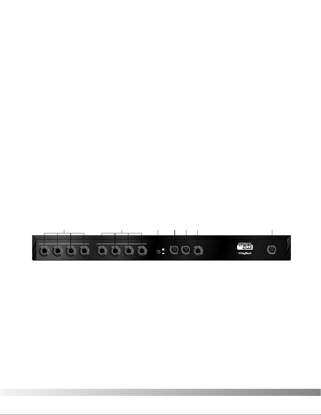
is illustrated in Figure 1-2.
Figure 1-2 Rear Panel
1) AUDIO INPUTS - These four inputs can be used for several differ-
ent combinations of input configurations. The Input Configuration
module of each Program defines how each Input is used. See
pg. 12 for more info.
2) AUDIO OUTPUTS - The Studio Quad's outputs can also be config-
ured in many different ways. These settings are found in the Output
Configuration module of each Program. See pg. 12 for more info.
3) OUTPUT LEVEL SWITCH - Selects whether the signal is nominally
output at line level (-10 dB) or at professional level (+4).
WARNING: Make sure the Studio Quad's power switch is off before chang-
ing the setting of this switch. Also, be sure you know which setting is best for
your particular equipment setup, as setting this switch to +4 can overload
the inputs of some line-level equipment. DigiTech is not responsible for any
damage to speakers or components due to misuse of this switch.
MANUFACTURED IN THE USA BY
SALT LAKE CITY, UTAH
INPUTS
1234
OUTPUTS
1234OUTPUT LEVEL
FOOTSWITCH
POWER
9VAC 2.2A
MIDI
IN
MIDI OUT/
THRU
-10
+4
3 456 712
7
Section 1 - Setting Up
Studio Quad Owner's Manual
4) MIDI IN - MIDI data is received at this port. When MIDI data is
received, the MIDI indicator in the display flashes on and off.
5) MIDI OUT / THRU - Merges MIDI data generated by the Studio
Quad with MIDI data received at the input.
6) FOOTSWITCH - This jack allows connection of the DigiTech FS300
3-button footswitch or any shorting-type footswitch. If using the
DigiTech FS300, button 1 increments through Programs, button 2
decrements through Programs, and button 3 bypasses the Studio
Quad's effects. Using any other single momentary switch device,
the switch acts as a Bypass.
Note: The footswitch must be plugged in on power up order for the
Studio Quad to detect which type of switch is being used.
7) POWER INPUT - Connect the included power supply to this jack. It
is a 4-pin DIN connector. Use only the DigiTech PS0920 power
supply with the Studio Quad.
MAKING CONNECTIONS
Because of its flexibility, the Studio Quad can be connected in several
different ways to meet the requirements of specific applications. The fol-
lowing diagrams offer some ways the Studio Quad can be connected.
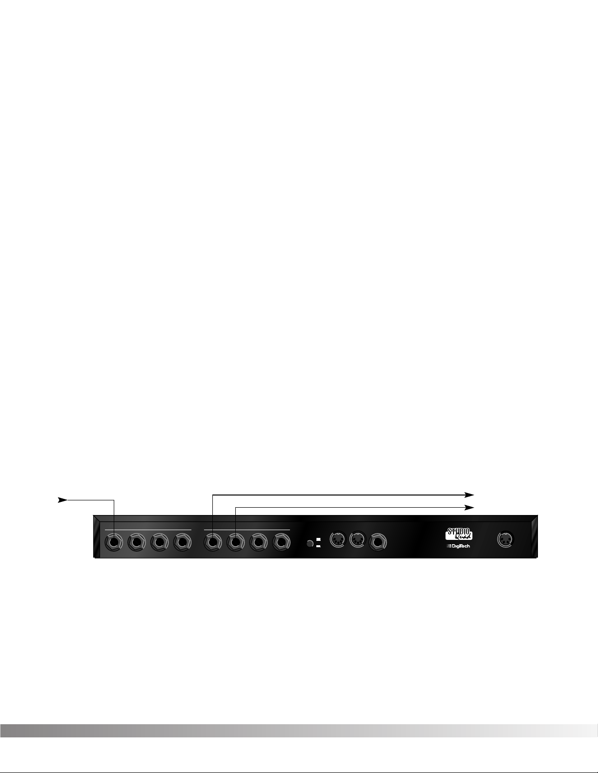
IN LINE: The Studio Quad can be connected between a line level
instrument output (such as keyboards, recording decks, etc.) and a
line level input (such as mixing console inputs). This method is called
the "in-line" method because the Studio Quad is connected directly in
the audio path of the source. When you use the in-line method, the
master wet-to-dry effects mix is controlled from the Studio Quad oper-
ating system. Cable routings for this method look like Figure 1-3:
Figure 1-3 In-Line Connection
MANUFACTURED IN THE USA BY
SALT LAKE CITY, UTAH
INPUTS
1234
OUTPUTS
1234OUTPUT LEVEL
FOOTSWITCH
POWER
9VAC 2.2A
MIDI
IN
MIDI OUT/
THRU
-10
+4
To Amplifier or Mixer
From Instrument or Direct Source
To Amplifier or Mixer
8
Section 1 - Setting Up
Studio Quad Owner's Manual
EFFECTS LOOP: This application uses the Studio Quad in an effects
loop of a mixing console. In this application, the source is routed
directly to the mixer channel input(s). From there, the Studio Quad
gets its source audio from the console's auxiliary send, and mix levels
are controlled directly from the console. Figure 1-4 shows a common
recording studio or live sound reinforcement setup for effects pro-
cessing with a console.
Figure 1-4 Effects Loop Configuration
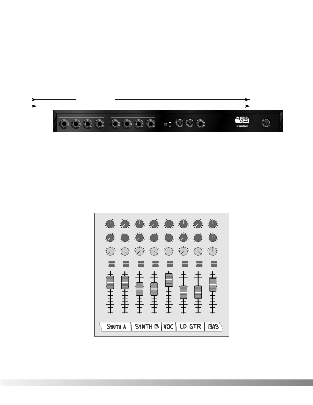
Figure 1-5 shows an example of a typical stereo effect setup as seen
from the console, and shows how to handle both true stereo and
mono input signals using two auxiliary sends.
This is the method of choice in many recording applications because
of the impressive realism and depth of texture that it produces. While
it is slightly more complicated to set up and requires twice as many
auxiliary sends, stereo effects (particularly reverbs) improve dramati-
cally in imaging and spaciousness.
Figure 1-5 Setting up a mixer's aux sends for true stereo operation
Pan
Mute
-10
0
+5
+10
-20
-30
-∞
-5
L / R
Mute
L / R
Mute
L / R
Mute
L / R
-5
-4
-3
-2
-1
0
+1
+2
+3
+4
+5
Pan
-5
-4
-3
-2
-1
0
+1
+2
+3
+4
+5
Pan
-5
-4
-3
-2
-1
0
+1
+2
+3
+4
+5
Pan
-5
-4
-3
-2
-1
0
+1
+2
+3
+4
+5
Pan
-5
-4
-3
-2
-1
0
+1
+2
+3
+4
+5
Pan
-5
-4
-3
-2
-1
0
+1
+2
+3
+4
+5
Pan
-5
-4
-3
-2
-1
0
+1
+2
+3
+4
+5
Pan
-5
-4
-3
-2
-1
0
+1
+2
+3
+4
+5
1234
-10
0
+5
+10
-20
-30
-∞
-5
-10
0
+5
+10
-20
-30
-∞
-5
-10
0
+5
+10
-20
-30
-∞
-5
Mute
L / R
5
-10
0
+5
+10
-20
-30
-∞
-5
Mute
L / R
6
-10
0
+5
+10
-20
-30
-∞
-5
Mute
L / R
7
-10
0
+5
+10
-20
-30
-∞
-5
Aux 1
0
2
46
8
10
Aux 2
0
2
46
8
10
Aux 1
0
2
46
8
10
Aux 2
0
2
46
8
10
Aux 1
0
2
46
8
10
Aux 2
0
2
46
8
10
Aux 1
0
2
46
8
10
Aux 2
0
2
46
8
10
Aux 1
0
2
46
8
10
Aux 2
0
2
46
8
10
Aux 1
0
2
46
8
10
Aux 2
0
2
46
8
10
Aux 1
0
2
46
8
10
Aux 2
0
2
46
8
10
Aux 1
0
2
46
8
10
Aux 2
0
2
46
8
10
Mute
L / R
8
-10
0
+5
+10
-20
-30
-∞
-5
Aux Send 1
Aux Send 2
Pan Control
MANUFACTURED IN THE USA BY
SALT LAKE CITY, UTAH
INPUTS
1234
OUTPUTS
1234OUTPUT LEVEL
FOOTSWITCH
POWER
9VAC 2.2A
MIDI
IN
MIDI OUT/
THRU
-10
+4
To Mixer Stereo Aux Return (L)
To Mixer Stereo Aux Return (R)From Mixer Aux Send 1
From Mixer Aux Send 2
9
Section 1 - Setting Up
Studio Quad Owner's Manual
REMEMBER: When you use this method to process stereo
sources such as keyboards, the auxiliary sends on your console
should be set up exactly opposite one another, as shown on
channels 1 and 2 of Figure 1-5. Note that the left channel is sent
to Aux 1, while the right channel is sent to Aux 2. When using
mono sources like vocals and bass guitar, send equal levels from
both Aux 1 and Aux 2 to maintain proper soundfield balance of
the effects, as shown on channels 5 and 8.
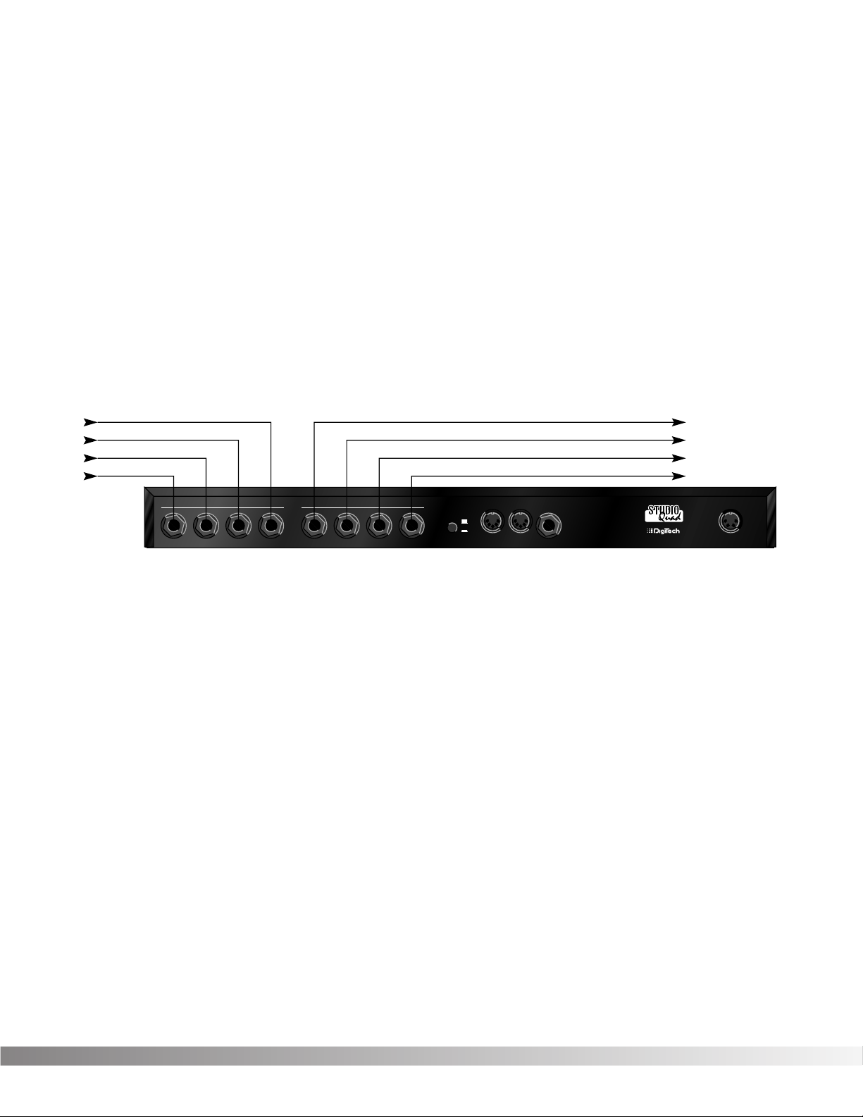
PARALLEL EFFECTS: Another application for the Studio Quad
allows you to independently process four discrete signals simultane-
ously. This method also utilizes the effects loops of your console, and
since each effect has a mono input, the auxiliary sends can be set up
in a much more straightforward way. Figure 1-6 shows how to connect
the Studio Quad for this application.
Figure 1-6 Quad Mono Input / Dual Stereo Output Configuration
Using this method, you could use channel 1 for a long vocal reverb,
channel 2 for a short gated snare drum reverb, channel 3 for lead gui-
tar delay, and channel 4 to thicken keyboard instruments with a
detuner. This method also offers the flexibility of running different
channels in-line or in an effects loop.
REMEMBER: Outputs can be configured any way you like, so
don't let any of this input / output stuff scare you.
A WORD ABOUT BYPASS
Because of its flexibility, the Studio Quad can be connected in several
different ways to meet the requirements of many specific applications.
However, the definition of Bypass may change in these different appli-
cations. The Studio Quad features Application Specific Bypassing so
that the Studio Quad functions appropriately in nearly every applica-
tions. When Bypassed, the Studio Quad simply switches the Effects in
that Program OFF, but the Dry Levels defined in that Program remain
untouched. If the effects are all wet (no Dry Level), the Bypass func-
tion effectively Mutes the Studio Quad. If the Dry Level is up, then the
Studio Quad passes the original signals through without processing.
Remember that the lines through the modules in the Effect
Configuration Matrix indicate that the modules are Bypassed.
MANUFACTURED IN THE USA BY
SALT LAKE CITY, UTAH
INPUTS
1234
OUTPUTS
1234OUTPUT LEVEL
FOOTSWITCH
POWER
9VAC 2.2A
MIDI
IN
MIDI OUT/
THRU
-10
+4
To Mixer Stereo Aux Return 2 (L)
To Mixer Stereo Aux Return 2 (R)
To Mixer Stereo Aux Return 1 (L)
To Mixer Stereo Aux Return 1 (R)
From Mixer Aux Send 3
From Mixer Aux Send 4
From Mixer Aux Send 1
From Mixer Aux Send 2

10
SECTION 2 - BASIC FUNCTIONS OF THE STUDIO QUAD
GETTING AROUND THE OPERATING SYSTEM
The menu structure of the Studio Quad has been specially designed
to be easy to use. The display shows the information you need, but to
make things even easier for you, illumination in the front panel buttons
offers additional operating information.
The front panel buttons give you information in one of two ways:
1 - If the button is DIMLY lit, its function is INACTIVE. Pressing a
dimly lit button causes it to light brightly and its function
becomes the active item in the display. If the DIMLY lit button
doesn’t light after you press it, the button is unavailable.
2 - If the button is BRIGHTLY lit, its function is ACTIVE. Pressing
an active button (other than the <PROGRAM> button) rese-
lects the already active item in the display.
PROGRAM MODE - Program mode allows you to scroll through the
Factory and User Programs using the Data Wheel. When the Studio
Quad is turned on, it sets itself to Program mode. Program mode is
active when the <PROGRAM> button is bright and a Program name is
present on the Information line (top line) of the display. You can toggle
between Factory or User Programs by pressing the <PROGRAM> but-
ton when it is brightly lit. The FACTORY PRG or USER PRG indicator
will light in the display according to which bank is selected. In this
mode, all other buttons on the front panel are dim or off.
To select a Program, do the following:
• Make sure Program mode is selected. If the <PROGRAM> but-
ton is dim, press <PROGRAM> once to return to Program mode.
• Use the <PROGRAM> button to select the Program bank
(Factory or User). Each successive press of the <PROGRAM>
button toggles between the Factory and User bank of Programs.
• Using the Data wheel, scroll to the Program you want to hear.
The selected program is immediately autoloaded. The AutoLoad fea-
ture can be turned off, allowing you to view a program before actually
loading it. See pg. 37 for further details.
FX EDIT MODE - This mode allows you to edit FX Modules, the
Modifier Module, the Input Mode Module, and the Output Mode
Module of your Programs. Use the <FX Edit> button to enter the FX
Edit mode and then to select the next module for editing. A helpful
hint, if you look at the Effect Routing Matrix while you press the FX Edit
button, the currently selected module will flash. The Studio Quad uses
Pages to navigate within an effect. A Page is a group of up to four
Section 2 - Basic Function of the Studio Quad
Studio Quad Owner's Manual
11
effect Parameters that appear on the screen at one time. To move
through the Pages in a Program, use the <NEXT PAGE> and
<PREV PAGE> buttons. Note that as you scroll through the Pages, the
Page indicator in the lower left corner of the display changes to show
the currently displayed Page.
SELECTING FX TYPES AND DEFAULTS
The Studio Quad has made custom digital signal processing easier
than ever by giving you access to a complete library of professionally
developed effects settings. Page one of every FX Module allows you to:
1) Bypass that effect module
2) Select an effect Type (Chorus, Reverb, Delay, etc.)
3) Select a Default for the selected effect Type
The Default parameter allows you to select one of several effect set-
tings stored in the Studio Quad's library. For example, there are 10
Dual Chorus defaults to choose from. All Factory Programs use these
Default settings. So, if you like the Chorus that is being used in
Factory Program 69, simply use the <4> button and the Data Wheel to
recall the default (which happens to be A2-Shallow) in your new pro-
gram. This eliminates the need to copy all those parameters from one
location to the other. It also gives you several starting places so you
can get as close as possible to the custom sound you are trying to
create. Once you edit one of the parameters in the FX Module, the
default name is replaced with the word "Custom". This means that a
default setting has been customized or changed by real-time
Modifiers for that program.
NOTE: There are two Banks available for the defaults, Bank A and
Bank B. Bank A contains the dry signal for typical in-line applications.
Bank B does not contain the dry signal, and boosts the effect level so
it can be used with a mixing console's effect loops . EQ, Panner,
Noise Gate, and Tremolo do not contain Dry level controls and there-
fore do not have a bank B available.
MODIFYING FX MODULE PARAMETERS EXAMPLE
Let's modify an effect Parameter. Factory Program 40 uses a quad
delay with a delay time of 500 milliseconds. The tap percentages are
set to DlyA = 25%, Dly B =50%, Dly C = 75%, and DLY D = 100%,
which gives you evenly spaced delay taps. But suppose they're too
slow to fit the tempo of a piece of music you're composing. With most
effects units, you'd have to recalculate each delay tap individually, but
USER PRG
SecSecmSec
Fx:Dual Cho Shallow
IN 4
IN 3
IN 2
IN 1
FACTORY PRG
- CHANGED
- CHANGED
MIDI
LEVEL 4
LEVEL 3
LEVEL 2
LEVEL 1
OUT 4
OUT 3
OUT 2
OUT 1
CLIP
FX EDIT PAGE
12 5678910
On
CHANGED CHANGED CHANGED
UTILITY PAGE
DIGITAL CLIPDIGITAL CLIP
4th 888 A 2
MODIFIERS
1 2 3 4
CLIP
CLIP
CLIP
C
C
C
C
C
C
C
C
S-DISC
™
PROCESSING
69
%kHz
m Sec
%kHz %kHz
m
%kHz
m
34
Section 2 - Basic Function of the Studio Quad
Studio Quad Owner's Manual
12
the Studio Quad makes it simple.
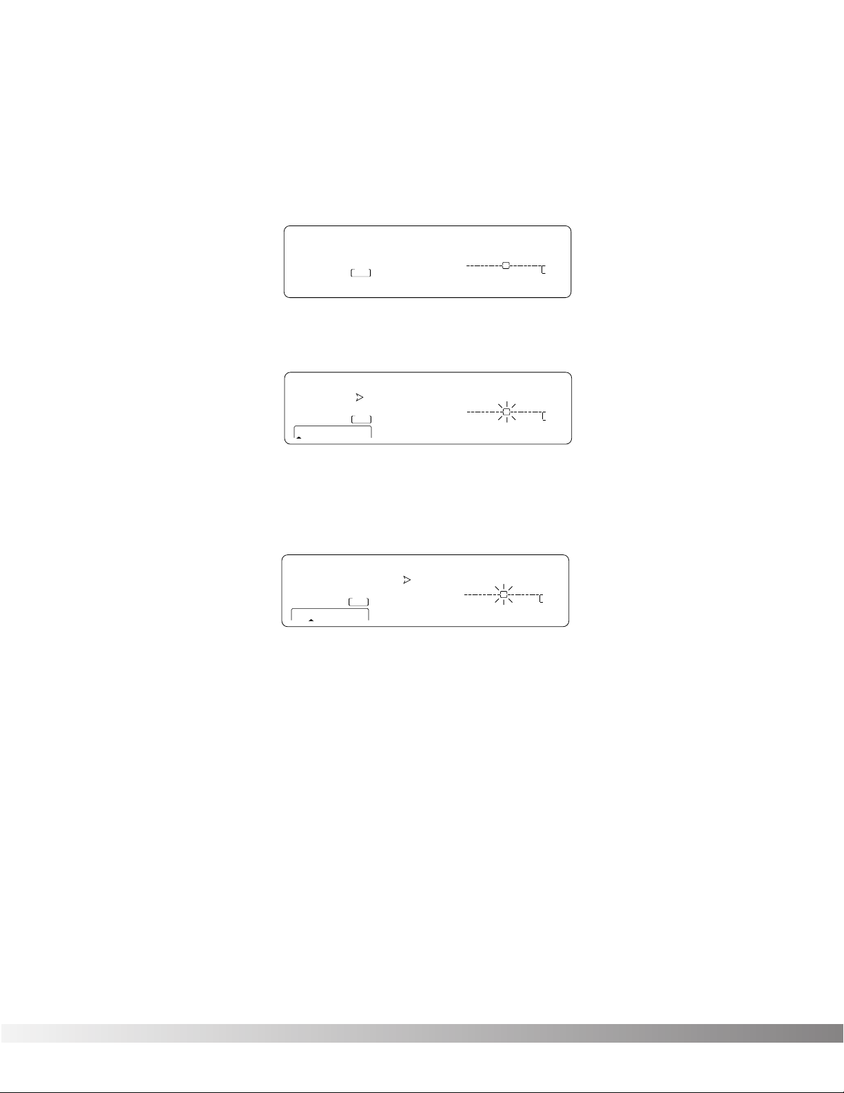
Here's how to change the tempo of the delays:
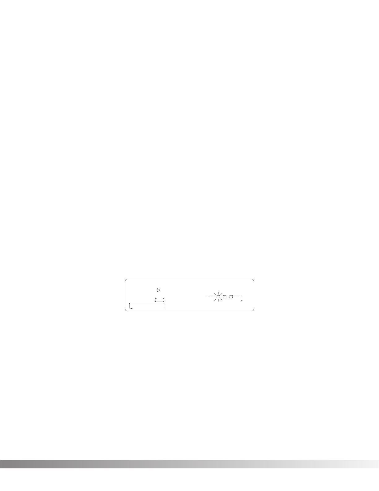
• If you're not already there, switch to Program mode and use the
Data wheel to scroll to Factory Program 40. The display reads:
• Press <FX EDIT>. Note: the current module being edited is
flashing in the Effect Routing Matrix. The display reads:
• Press <NEXT PAGE> twice. Position 2 of the Information line
shows that the current delay time setting is 500 milliseconds.
Remember that the total delay time shown in the display is divid-
ed among the delay taps in the Module. The display reads:
• Use the Data Wheel to decrease the delay time. Both that the
Store button illuminates and the CHANGED icons turn on indi-
cating that the Program has been modified.
• Press the <Program> button to return to Program Mode, or con-
tinue in Edit Mode by continuing to press the <FX EDIT> button.
Note: Make sure you store the settings after you have made any
changes. See pg. 16 for more information.
EFFECT & INPUT / OUTPUT CONFIGURATIONS
The Studio Quad's ability to accommodate a number of different input
and output routing configurations makes it an extremely useful and
flexible tool for many different applications.
Programs 1 through 12 in the Factory Program bank represent all the
FX module configurations available in the Studio Quad. For diagrams
of these 12 Effect Configurations, see pg. 41. When you find one that
USER PRGUSER PRG
SecSecmSec
Delay Time FdBck TapIt
IN 4
IN 3
IN 2
IN 1
FACTORY PRG
- CHANGED
- CHANGED
MIDI
LEVEL 4
LEVEL 3
LEVEL 2
LEVEL 1
OUT 4
OUT 3
OUT 2
OUT 1
CLIP
FX EDIT PAGE
12 5678910
On
CHANGED CHANGED
UTILITY PAGE
DIGITAL CLIP
500 40 __
MODIFIERS
1 234
CLIP
CLIP
CLIP
C
C
C
C
C
C
C
C
S-DISC
™
PROCESSING
40
%kHz
m Sec
%kHz %kHz
m
%kHz
m
34
USER PRGUSER PRG
SecSecmSec
Fx:StQuad Dly RoundNRnd
IN 4
IN 3
IN 2
IN 1
FACTORY PRG
- CHANGED
- CHANGED
MIDI
LEVEL 4
LEVEL 3
LEVEL 2
LEVEL 1
OUT 4
OUT 3
OUT 2
OUT 1
CLIP
FX EDIT PAGE
12 5678910
On
CHANGED CHANGED
UTILITY PAGE
DIGITAL CLIP
4th 888 a 1
MODIFIERS
1 2 3 4
CLIP
CLIP
CLIP
C
C
C
C
C
C
C
C
S-DISC
™
PROCESSING
40
%kHz
m Sec
%kHz %kHz
m
%kHz
m
34
USER PRG
SecSecSec
1:Rythmic Multi-Tap
IN 4
IN 3
IN 2
IN 1
FACTORY PRG
- CHANGED
- CHANGED
LEVEL 4
LEVEL 3
LEVEL 2
LEVEL 1
OUT 4
OUT 3
OUT 2
OUT 1
FX EDIT PAGE
1 2 3 4
On Off 2
MODIFIERS
1 34
S-DISC
™
PROCESSING
40
%kHz
m
%kHz
m
%kHz
m
Section 2 - Basic Function of the Studio Quad
Studio Quad Owner's Manual
13
you like, you can save it in a new User Program location for later use.
Remember that choosing an Effect Configuration does not define the
input / output routing schemes or the actual effects used within the
configuration. This means that even one configuration can be used
thousands of different ways.
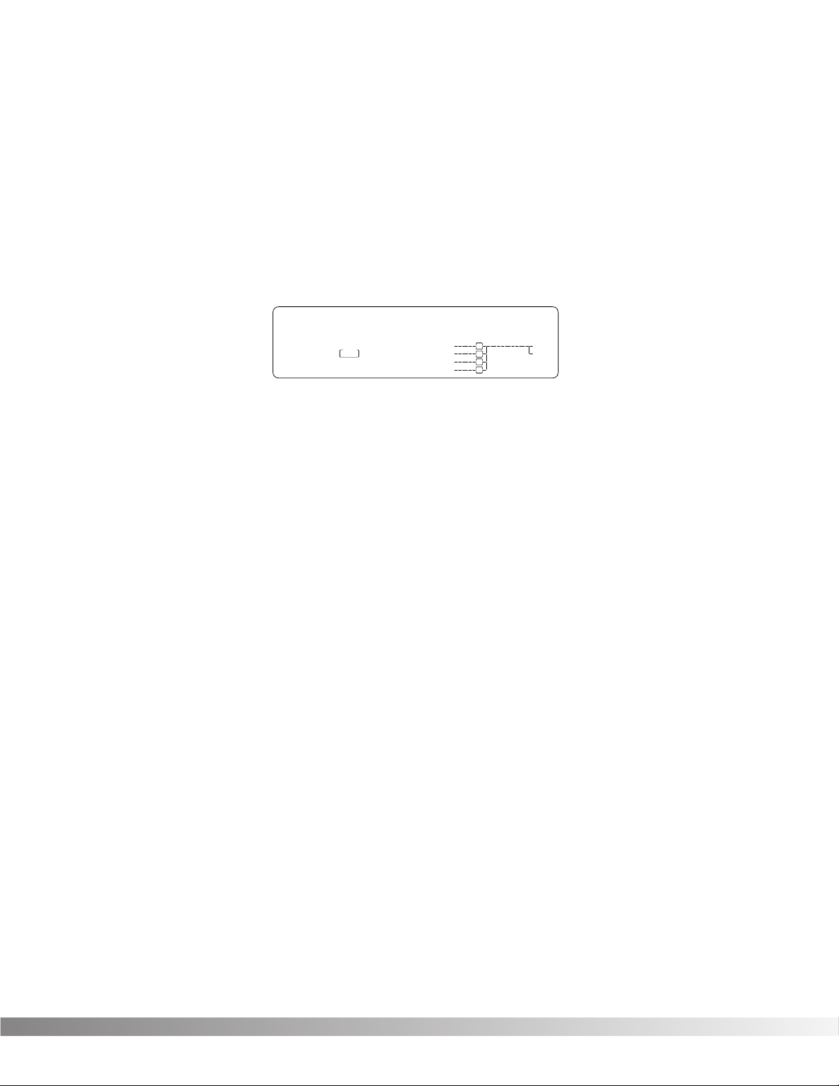
To select a new Effect Configuration, do the following:
• Scroll through Factory Programs 1 - 12 until you find a configu-
ration you want to use. The display looks something like this:
Once you have selected an Effect Configuration, you can select the
input/output configuration you will be using.
•Press the FX Edit button until the input section of the Effect
Routing Matrix begins flashing and the information line reads:
Input Mode: Quad Mono
• Use the Data Wheel to scroll through the available input configu-
rations.
• Press the FX Edit button until the output section of the Effect
Routing Matrix begins flashing and the information line reads:
Output Mode: Stereo
• Use the Data Wheel to scroll through the available output config-
urations.
Note: Make sure you store the settings after you have changed
anything. See pg. 16 for more information.
USING MODIFIERS
Modifiers are unique tools that can be used to dramatically alter your
sound based on information from signal amplitude, the settings of a Low
Frequency Oscillator (LFO) or MIDI Continuous Controller information.
Every Program in the Studio Quad has a set of Modifiers. Up to 8
Modifier links can be assigned to control parameters. There are three
types of Modifiers that can be linked to a parameter; MIDI CCs, LFOs,
and Dynamic (signal level dependent).
USER PRG
SecSecmSec
1:Rvb 2:GtRv 3:Dly 4:Cho
IN 4
IN 3
IN 2
IN 1
FACTORY PRG
- CHANGED
- CHANGED
MIDI
CHANGED
LEVEL 4
LEVEL 3
LEVEL 2
LEVEL 1
OUT 4
OUT 3
OUT 2
OUT 1
CLIP
FX EDIT PAGEFX EDIT PAGE
1 2 5 6 7 8 9 10
Off
CHANGED CHANGED CHANGED
UTILITY PAGEUTILITY PAGE
DIGITAL CLIPDIGITAL CLIP
888 888 888
MODIFIERS
1 234
CLIP
CLIP
CLIP
C
C
C
C
C
C
C
C
S-DISC
™
PROCESSING
1
%kHz
m Sec
%kHz %kHz
m
%kHz
m
3 4
Section 2 - Basic Function of the Studio Quad
Studio Quad Owner's Manual
 Loading...