


®
Motion Sensor Light
Control
Model 5412
Features
•Turns on lighting when motion is detected.
•Automatically turns lighting off.
•Photocell keeps the lighting off during daylight hours.
•LED indicates motion was sensed (day or night).
This package includes:
Mounting Bolt
Plastic |
|
Hanger |
Rubber Plug |
|
|
Lamp Holders |
|
2 Shells
Cover 
Plate
Sensor 
 Gasket
Light Control
Mounting Strap
2 Wire
Connectors
6 Screws
2 Flood Lamps (3 sizes included) (some versions)
Requirements
•The Light Control requires 120-volts AC.
•If you want to use Manual Mode, the control must be wired through a switch.
•Some codes require installation by a qualified electrician.
•This product is intended for use with the enclosed gasket and with a junction box marked for use in wet locations.
OPERATION
Mode: |
On-Time |
Works: Day |
Night |
Test |
5 Seconds |
x |
x |
Auto |
1, 5, or 10 Minutes |
|
x |
Manual |
To Dawn* |
|
x |
* resets to Auto Mode at dawn.
Note: When fi rst turned on wait about 1 1/2 minutes for the circuitry to calibrate.
TEST
Put the ON-TIME switch on the bottom |
|
ON-TIME |
|
||||
of the sensor in the TEST position. |
|
|
|
|
|
|
|
|
|
|
|
|
|
|
|
|
|
10 5 1 TEST |
|||||
|
|
|
|
|
|
|
|
AUTO |
|
|
|
|
|
|
|
|
|
|
|
|
|
|
|
Put the ON-TIME switch in the 1, 5, |
ON-TIME |
||||||
or 10 minute position. |
|
|
|
|
|
|
|
|
|
|
|
|
|
|
|
|
10 5 1 TEST |
||||||
|
|
|
|
|
|
|
|
MANUAL MODE |
|
|
|
|
|
|
|
Manual mode only works at night because daylight returns the sensor to AUTO.
Flip the light switch off for one second then back on to toggle between AUTO and MANUAL MODE.
Manual mode works only with the ON-TIME switch in the 1, 5, or 10 position.
1 Second OFF
then...
... back on.
|
Mode Switching Summary |
|||||||
|
|
|
|
|
|
|
||
|
TEST |
|
|
|
|
Move ON-TIME Switch to |
||
|
|
|
|
|
|
|
|
1, 5, or 10 minutes |
|
|
|
|
|
|
|
|
|
|
AUTO |
|
|
|
|
|
||
|
|
|
|
|
|
|
|
Flip light switch off |
|
|
|
|
|
|
|
|
|
|
|
|
|
|
|
|
|
for one second then |
|
|
|
|
|
|
|
|
back on* |
MANUAL MODE |
|
|
|
|||||
|
|
|
|
|||||
|
|
|
|
|
|
|
|
|
*If you get confused while switching modes, turn the power off for one minute, then back on. After the calibration time the control will be in the AUTO mode.
© 2006 DESA Specialty Products™ |
598-1273-00 |

INSTALLATION
For easy installation, select an existing light with a wall switch for replacement.
|
|
|
|
|
|
|
|
|
|
|
|
|
|
|
|
|
|
|
|
|
|
|
|
|
|
|
|
|
|
|
|
|
|
|
|
|
|
|
|
|
|
|
|
|
|
|
|
|
|
|
|
|
|
|
|
|
|
|
|
|
|
|
|
|
|
|
|
|
|
|
|
|
|
|
|
|
|
|
|
|
|
|
|
Wall Mount |
Eave Mount |
||||||||||
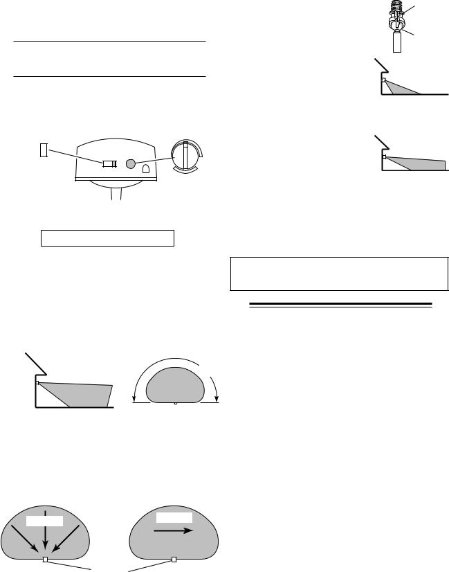
For under eave installation, the sensor head must be rotated as shown in the next two steps for proper operation and to avoid the risk of electrical shock.
For eave mount only:
Swing the sensor head towards the clamp screw joint.
Controls
Clamp Screw
Then rotate the sensor head clockwise 180° so the controls face down.
Controls
Controls
If the sensor pops out of the ball joint, loosen the clamp screw and push the sensor back into the ball joint. Tighten the clamp screw when done.
WIRE THE LIGHT CONTROL
 WARNING: Turn power off at the fuse or circuit breaker.
Remove the existing light fi xture.
Install the mounting strap as shown using two screws that fi t your junction box.
The plastic hanger can be used to hold the fi xture while wiring. The small end of the plastic hanger can be threaded through the hole in the center of the cover plate. The small end then goes into one of the slots on the mounting strap.
Route the Light Control’s wires through the large gasket holes.
Twist the junction box wires and fixture wires together as shown. Secure with wire connectors.
Mounting |
Black to |
|
White to |
Strap |
Black |
|
White |
|
|
|
|
Rubber
Plug
Mounting
Bolt
Gasket
Junction box ground wire to green ground screw on fixture.
MOUNT THE LIGHT CONTROL
Align the Light Control cover plate and cover plate gasket. Secure with the mounting bolt.
Align the three slots in the decorative shell with the lamp holder pins. Push the shell in and then twist clockwise to lock. Repeat for other shell.
Shell Slot
Push the Rubber Plug fi rmly into place.
If a wet location junction box was not used, caulk the wall plate mounting surface with silicone weather sealant.
To avoid water damage and electrical shock, keep lamp holders 30° below horizontal.
|
Keep lamps at least |
|
1" (2.5 cm) from the |
Lock Nut |
sensor.Do not allow |
|
the lamps to block |
Lens |
the lens. |
Adjust the lamp holders by loosening the lock nuts but do not rotate the lamp holders more than 180°
from the factory setting. When screwing in the fl oodlamps, do not overtighten.
2 |
598-1273-00 |
TEST AND ADJUSTMENT
Turn on the circuit breaker and light switch.
NOTE: Sensor has a 1 1/2 minute warm up period before it will detect motion. When fi rst turned on, wait 1 1/2 minutes.
Turn the RANGE control to the mid position and the ON-TIME control to the TEST position.
ON-TIME |
RANGE |
|||||
|
|
|
|
|
|
|
|
|
|
|
|
|
|
|
|
|
|
|
|
|
10 5 1 TEST
MIN MAX
Bottom of Sensor
Avoid aiming the control at:
•Objects that change temperature rapidly, such as heating vents and air conditioners. These heat sources could cause false triggering.
•Areas where pets or traffic may trigger the control.
•Nearby large, light-colored objects refl ecting light may trigger the shut-off feature. Do not point other lights at the sensor.
180°
8 ft.
(2.4 m)
70 ft.
(21 m)
Maximum Range |
Maximum |
|
Coverage Angle |
The detector is most sensitive to motion across its fi eld of view.
Motion |
Motion |
|
Sensor
Least Sensitive |
Most Sensitive |
Loosen the clamp screw in the sensor ball joint and gently rotate the sensor.
Walk through the coverage area noting where you are when the lights turn on (also, the LED will fl ash several times when motion is detected).Move the sensor head up, down, or sideways to change the coverage area. Keep the sensor at least 1" (2.5 cm) away from the lamps.
Adjust the RANGE as needed. RANGE set too high may increase false triggering.
Secure the sensor head by tightening the clamp screw.
Do not overtighten the screw.
Clamp
Screw
Ball
Joint
Aim Sensor Down for Short Coverage
Aim Sensor Higher for Long Coverage
Set the amount of TIME you want the lights to stay on after motion is detected (1, 5, or 10 minutes).
 WARNING: Risk of fire. Do not aim the lamps at a combustible surface within 3 ft. (1 m).
SPECIFICATIONS
Range . . . . . . . . . . . . Up to 70 ft. (21 m) [varies with surrounding temperature].
Sensing Angle . . . . . . Up to 180°
Electrical Load. . . . . . Up to 300 Watt Maximum Incandescent [Up to 150 Watt maximum each lamp holder.]
Power Requirements . 120 VAC, 60 Hz
Operating Modes . . . . TEST, AUTO, and MANUAL
MODE
Time Delay . . . . . . . . 1, 5, 10 minutes Range . . . . . . . . . . . . Adjustable
DESA Specialty Products reserves the right to discontinue products and to change specifi cations at any time without incurring any obligation to incorporate new features in products previously sold.
598-1273-00 |
3 |
 Loading...