


 Loading...
QUICK START GUIDE
Cisco ASA 5580
1Verifying the Package Contents
2Powering On the ASA
3Maximizing Throughput
4Connecting Interface Cables and Verifying Connectivity
5Launching ASDM
6Running the Startup Wizard
7(Optional) Allowing Access to Public Servers Behind the ASA
8(Optional) Running VPN Wizards
9(Optional) Running Other Wizards in ASDM
10Advanced Configuration
Regulatory Compliance and Safety Information
Read the safety warnings in the Regulatory Compliance and Safety Information (RCSI), and follow proper safety procedures when performing the steps in this guide. See http://www.cisco.com/go/asadocs for links to the RCSI and other documents.
Revised: January 30, 2012, 78-20726-01
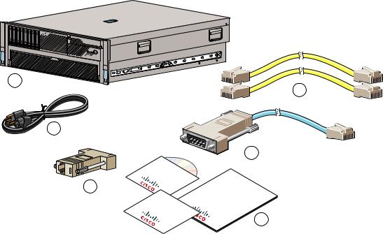
1 Verifying the Package Contents
Verify the contents of the packing box to ensure that you have received all items necessary to install your ASA.
1
5
2
Ad |
a |
C |
isc |
|
A ptive |
|
|||
|
p |
|
|
|
Produ lian |
|
|||
|
p |
|
|
|
|
ct |
|
|
|
|
C |
D |
|
|
Ci |
|
|
|
|
|
sco |
|
|
|
SecurityASA |
Adaptive |
|||
Product |
|
|
||
|
|
CardAppliance |
||
|
|
4 |
Cisco |
|
|
SecurityASA |
|
|
Quick |
|
Adaptive |
|
Appliance |
|
GuideStart |
||
6
300012
1 |
ASA 5580 Chassis |
2 |
2 Yellow Ethernet Cables |
|
|
|
|
3 |
Power Cable (US Shown) |
4 |
Blue Console Cable PC Terminal Adapter |
|
|
|
|
5 |
RJ-45 to DB-9 Adapter |
6 |
Documentation and Software CD |
|
|
|
|
|
Not shown: Rail System Kit |
|
|
|
|
|
|
2
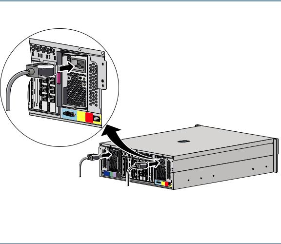
2 Powering On the ASA
Step 1 Attach the power cable to the back of the ASA. If you have redundant power supplies, you must connect both power cables to the back of the chassis.
3 |
PCI-X |
100 MHz |
|
PS1
CONSOLE |
Reserved |
for |
|
|
Future Use |
MGMT 0/0
PS1
UID
CONSOLE |
Reserved |
for |
|
|
Future Use |
MGMT 0/0
300014
Step 2 Connect the power cable(s) to the electrical outlets.
Step 3 Power on the ASA.
Step 4 Check the Power LED on the front of the ASA; if it is solid green, the device is powered on.
Step 5 Check the System LED on the front of the ASA; after it is solid green, the system has passed power-up diagnostics.
3

3 Maximizing Throughput
Refer to the following illustration when planning your network for maximum throughput.
Slot 9 (Reserved) |
Slots 1, 2 (Reserved) |
PCI-E x4 |
PCI-E x8 |
|
PCI-E x4 |
PCI-E x8 |
|
PCI-E x4 |
PCI-X 100 MHz |
|
9 |
8 |
7 |
6 |
5 |
4 |
3 |
2 |
1 |
Slots 7, 8 |
|
|
|
|
|
|
|
Slots 3, 4, 5, 6, |
(I/O Bridge 2) |
|
|
|
|
|
|
|
Management Ifcs |
|
|
|
|
|
|
|
|
(I/O Bridge 1) |
Slots 5, 7, 8 (High Capacity Bus, |
Slots 3, 4, 6 (Normal Capacity Bus, |
PCI Express x8 non-hot-plug) |
PCI Express x4 non-hot-plug) |
331348
•You should use the high-capacity bus slots (5, 7, 8) for 10-Gigabit Ethernet adapters; other adapters can be placed in any slot.
•Distribute traffic on the I/O bridges using the following best practices:
–Have equal amounts of traffic on both I/O bridges.
–Keep traffic flow within the same I/O bridge.
For example, the ideal traffic distribution would be:
a.Half the traffic stays on slots 7 and 8.
b.The other half of the traffic stays on slots 3 through 6.
Steps a and b achieve both best practices above. If you cannot achieve both practices, then you should prefer the first best practice: have equal amounts of traffic on both I/O bridges.
See the Hardware Installation Guide for more information about maximizing throughput on the ASA 5580.
4
Loading...