


Instantaneous gas water heater
POWER VENTED - ELECTRONIC IGNITION
Model
WR430-7K
•installation
•operation
•maintenance
The Bosch instantaneous water heater is a high efficiency, space saving answer to your water heating needs. All Bosch instantaneous water heaters heat water only as required; no energy is lost maintaining a large volume of water at elevated temperatures as in tank-type storage water heaters. Suitable for heating potable water only. Not approved for space heating purposes.
6 720 606 599 CA (03.11) AL
READ INSTRUCTIONS CAREFULLY BEFORE INSTALLING
NOTICE TO INSTALLER: Please leave this manual with the owner or affix adjacent to appliance.
ASTRAVAN DISTRIBUTORS, LTD.
123 Charles Street
North Vancouver, B.C. V7H 1S1
Phone Canada: (604) 929-5488
Phone USA: (206) 860-8448
Web Site: www astravan.com
WARNING: If the information in this manual is not followed exactly, a fire or explosion may result causing property damge, personal injury or death.
-Do not store or use gasoline or other flammable vapors and liquids in the vicinity of this or any other applicance
-WHAT TO DO IF YOU SMELL GAS
•Do not try to light any appliance.
•Do not touch any electrical switch; do not use any phone in your building.
•Immediately call your gas supplier from a neighbor’s phone. Follow the gas supplier’s instructions.
•If you cannot reach your gas supplier, call the fire department.
-Installation and service must be performed by a qualified installer, service agency or the gas supplier.
Note: In case of problems please contact your salesman or installer

BOSCH WR430-7K
Principle of Operation:
When a hot water faucet is opened, the flow of water through the heater causes the gas valve to open. At the same time a microswitch is activated which sends a spark to the pilot. The flame sensor confirms that the pilot has been lighted and allows burners to ignite. The pilot goes out. The power exhaust system runs as long as the burners are on. The heat exchanger coils absorb the heat generated by the burners and transfer heat to the water. When the hot water faucet is shut off, the gas valve automatically closes and the burners turn off, followed immediately by the exhaust system. Your hot water faucet is an ignition key to turn on the water heater, giving you control over your hot water energy use. Every time you turn off your hot water faucet, the energy consumption for hot water returns to zero.
FEATURES
-Power Venting with safety shutoff
-Electronic Pilot Ignition
-On/Off switch to activate system
-High Quality Materials for Long Working Life.
-Copper heating coils for endless supply of hot water.
-Burner output proportional to hot water flow demand for maximum energy efficiency.
-Safety flame sensor at pilot burner.
-Automatic over heating protection shut-off sensor.
-Stainless steel burners with stabilized blue flame.
-Built-in corrosion resistant power venter.
-Compact space saver: mounts on a wall with two hooks.
-Easily removable one-piece cover.
-Easy one person installation.
-Adjustable water flow restrictor ensure that water flow demand will not exceed the heating capacity of the heater.
|
NAT. GAS |
PROPANE |
|
|
|
|
|
max. |
130 000 Btu/hr |
125 000 Btu/hr |
|
Gas Input |
|
|
|
28 000 Btu/hr |
28 000 Btu/hr |
||
min. |
|||
|
|
|
Water Connection 1/2” Thread fitting
H x W x D 29 3/4” x 18 1/4” x 8 3/4”
Vent 4” (Category III Gas Appliance)
Max. lineal vent pipe length 15" (4.5m)
Gas Connection 1/2” NPT thread
Minimum recommended house supply pressure 40 Psi
Warm position minimum water pressure 18 psi (no fittings)
Hot position minimum water pressure13 psi (no fittings)
Max. Water Pressure 150 Psi
Shipping Weight 55 Lbs
Net Weight 44 LB
2.5 GPM at 90° rise (32°C) (9.5 l)
5.0 GPM at 45° rise (16°C) (19.5 l)
Min. Water Flow 1/2 gal/min
120V/60Hz 1.2 Amps
LP GAS Supply Pressure inlet. min. 11”W.C.*
LP GAS regulator outlet pressure 9.9”W.C.*
Natural Gas Pressure inlet |
min.: |
7”W.C.* |
Natural Gas Regulator Pressure 5.38 W.C.**
* Inlet gas pressure must not exceed this value
** For purposes of input adjustment
ELECTRICAL 3 ft. ( 0.9 m) power cable supplied c/w CSA 3 prong plug.
UNPACKING THE BOSCH WR430-7K HEATER
This heater is packed securely. The box includes two water connection fittings, a control knob, a gas pressure regulator, a pressure relief valve, an incandescent particle tray, two hooks for hanging the heater, this manual. Do not lose this manual as there is a charge for replacement.
2 |
6 720 606 599 |

DIMENSIONS
EXTERIOR
TERMINATION
Figure 1
Maximum Hydrostatic water pressure - 1.03 MPa (150 p.s.i.)
Maximum recommended working pressure - 0.69 MPa (100 p.s.i.)
Minimum working pressure - 0.09 MPa (13 p.s.i.) no piping attached
Reccomended pressure for showers and domestic, 0.27 MPa (40 p.s.i.)
Model |
Type of Gas |
Altitude |
Input |
Main Burner Orifices |
||
|
|
|
|
Size, mm |
Qt. |
|
|
natural gas |
standard |
130 000 Btu/hr (38 kW) |
1.20 diam. |
18 |
|
WR430-7.K.. |
propane/LP |
(0 - 2 000 ft) |
125 000 Btu/hr (36.6 kW) |
0.79 diam. |
18 |
|
natural gas |
high * |
117 000 Btu/hr (34.3 kW) |
1.20 diam. |
18 |
||
|
||||||
|
propane/LP |
(2 000 - 4 500 ft) |
112 000 Btu/hr (32.8 kW) |
0.79 diam. |
18 |
|
•The high altitude ratings listed are Canadian Gas Association high altitude ratings and are valid only in Canada. In the U.S., the National Fuel Gas Code, ANSI Z223.1-1988, recommends for high altitude installations above 2,000 feet, that the input rate be reduced 4% for each 1,000 feet above sea level. - See page 15.
6 720 606 599 |
3 |

FORWARD
The design of the WR430-7K complies with CAN 1-4.3 and ANSI Z21.10 (latest edition) as an instantaneous gas water heater. In addition, the WR430-7K also complies with CAN 1-2.17 for use at high altitudes, 2,000 - 4,500 ft. above sea level.
Installation, operation and maintenance instructions are provided in this manual. Installation and operation instructions should be thoroughly reviewed before proceeding with installation of the BOSCH instantaneous gas water heater.
The BOSCH instantaneous gas water heater is designed to operate on natural or propane gas: however, make sure that gas on which heater is to operate is the same as specified on the heater’s model/rating plate.
In addition to these instructions, the water heater shall be installed in accordance with CAN/CGA-B149 Installation Code (in Canada) or Z223.1-latest edition, National Fuel Gas Code (in U.S.A.) and/or local installation codes. These shall be carefully followed in all cases.
INSTALLATION INSTRUCTIONS
The Bosch WR430-7K is a high efficiency fin tube heater and should not be installed and operated during construction or building renovations if location is exposed to above normal dust levels. This can cause dust build up in the finned heat exchanger and result in damage to heater and be a hazard to health.
Note: Proper plumbing, venting, gas connections and an adequate supply of combustion air are required for safe and reliable operation. Ability equivalent to that of a licensed tradesman in the field involved is required for installation and/or service of these water heaters.
LOCATION
Before installing the BOSCH instantaneous gas water heater, consideration must be given to proper location. The location should be as close to outside vent termination as practicable, in an area with an adequate air supply and as centralized with the piping system as possible. The heater should not be located in an area where it will be subject to freezing. The heater should be located in an area where leakage of the heater or its connections will not result in damage to the area adjacent to the heater or to lower floors of the structure. See venting page 6.
Note: When such locations cannot be avoided, it is recommended that a suitable drain pan, adequately drained, be installed under the water heater. The pan must not restrict combustion air flow.
ELECTRICAL
A grounded switched plug receptable must be provided immediately below the left hand corner of heater to accept and provide power to supplied 3 ft. (0.9m) appliance cable and plug.
AIR REQUIREMENTS
For safe operation, sufficient air for combustion, ventilation and dilution of flue gases must be available. An insufficient supply of air will result in a yellow luminous burner flame, causing carboning or sooting of the heat exchanger.
In order to prevent corrosion, make sure that the combustion air is kept free of aggressive substances. Substances that especially contribute to corrosion are halogenated hydrocarbons (e.g., chlorine and fluorine) which are contaned in solvents, paint, adhesives, propellant gases, various household cleaners, etc. Take precautionary measures as necessary.
In unconfined spaces, in buildings of normal construction, infiltration normally is adequate to provide air for combustion, ventilation and dilution of flue gases. However, a confined space must be provided with two permanent openings to provide combustion and ventilation air to the appliance. Each opening shall have a free area of one square inch per 1,000 Btu/Hr* of total input rating of all the appliances in the enclosure. One opening shall be within 12 inches of the top and one within 12 inches of the bottom of the enclosure.
* Special Note
When the WR430-7K is installed in a confined space of minimum size the openings described above must be increased in to a size of 1-1/2 square inches per 1,000 BTU/Hr. In other words, when installed in a minimum sized confined space the two openings that are to be made in the enclosure within 12 inches of the top and 12 inches of the bottom must each have a minimum free area of, (1 - 1½” - 2" x (130) = 195 square inches.
4 |
6 720 606 599 |

For either a confined or unconfined space in a building of tight construction with inadequate infiltration, air must be drawn from the outdoors or from spaces that freely communicate with the outdoors. Two permanent openings located as indicated are to be provided as follows:
MOUNTING
The WR430-7K is design certified for mounting to a wall. The heater must not be installed on a carpeted wall. The heater must be mounted to the wall using appropriate anchoring materials.
1.When communicating with outdoors directly or by
means of vertical ducts, each opening shall have a Note: If wall is a stud wall sheathed with plasterboard it is
free area of not less than one square inch per 4,000 BTU/Hr. of total input of all appliances in the space.
2.When communicating with outdoors by means of horizontal ducts, each opening shall have a free area of not less than one square inch per 2,000 BTU/Hr. of total input of all appliances in the space.
For detailed requirements see:
•in Canada, CAN/CGA-B149 Installation Codes
•in U.S.A., ANSIZ223.1-latest edition, National Fuel Gas Code.
WARNING!
1.Flammable materials, gasoline, pressurized containers, or any other items or articles that are potentially fire hazards must never be placed on or adjacent to the heater. The appliance area must be kept free of all combustible materials, gasoline and other flammable vapors and liquids.
2.Do not obstruct the flow of combustion and ventilation air to the appliance.
CLEARANCE
The WR430-7K is design certified for installation on a combustible wall and for installation in an alcove or closet with minimum clearances to combustible construction of 0 mm from back, 102 mm (4 inches) from sides, 305 mm (12 inches) from top and bottom, and 102 mm (4 inches) from front. A minimum of 305 mm (12 inches) shall be allowed for maintenance of serviceable parts. Clearance from vent is dependent upon the clearance rating of the venting material used; see venting page 6.
recommended that support board(s), either 1 x 4's or 1/2” (minimum) plywood first be attached across a pair of studs and then the heaters should be attached to the support boards. See Figure 2.
Figure 2
WALL STUDS
SUPPORT BOARD
1” X 4”
SPACE BOARD
Fig. 2 - Mounting the Heater
Expansion and contraction of piping due to changing water temperature in the pipes imparts movement to the heater which, if mounted directly to a brittle, friable board, such as plasterboard, can cause failure of mounting.
Warning!
Check Flue Gas Safety Device good functioning, please proceed as explained in "Flue gas safety device" page 16.
THIS APPLIANCE MUST BE INSTALLED IN ACCORDANCE WITH THE NATIONAL FUEL GAS CODE ANSI Z223.1- latest edition in U.S.A. or CAN/CGA-B149 INSTALLATION CODES IN CANADA. LOCAL CODES AND/OR THE REQUIREMENTS OF THE AUTHORITY HAVING JURISDICTION MUST BE FOLLOWED.
6 720 606 599 |
5 |

Bosch POWER VENTING SYSTEM
INTRODUCTION
Bosch power venting models are designed to overcome difficult venting problems which cannot be performed with atmospheric venting: to meet your hot water demand load very efficiently, with an environmentally friendly appliance which conserves energy and significantly reduces combustion emissions to atmosphere.
GENERAL INFORMATION
This Power Vent System must be installed by a *qualified installer in accordance with all applicable local gas and electrical codes and in the absence of:
•With the current CAN1/CGA B149 installation code for gas burning appliances and the Canadian Electrical code C22.1-M90 part 1 (for Canada).
•With the National Fuel Code and the ANSI Z223.1-LATEST and National Electrical Code ANSI/NFPA No 70-LATEST electrical code (for USA).
The Bosch warranty will be voided by, and Bosch disclaims any responsibility for the following actions:
•Use of any unapproved venting component part not manufactured or approved by Bosch in combination with the Bosch WR430-7K unit.
•The Bosch WR430-7K must not be modified in any way when installing the Power Vent System. All systems must be installed as per Bosch Installation Guide.
•Installation other than instructed in this manual.
CAUTION:
Bosch Power Vent System must be installed by a qualified agency in accordance with these instructions. If improperly installed a hazardous condition such as an explosion or Carbon Monoxide poisoning could result. Bosch will not be responsible for any and all improperly installed appliances.
*QUALIFIED INSTALLING AGENCY: Any individual, firm, corporation or company which either in person or through a representative is engaged in and is responsible for the installation and operation of gas appliances and draft control devices, who is experienced in such work, familiar with all precautions required, and has complied with all the requirements of the authority having jurisdiction.
GENERAL VENTING INFORMATION
SIZING & DISTANCES:
Plan the vent system so that code clearances and manufacturer’s distances are maintained from combustible materials, plumbing and wiring.
This unit may be directly connected to approved vent termination with a 90° elbow or located with a maximum lineal length of 15 ft. (4.6m) including two 90° elbows from termination. All vent pipe and fittings must only be 4” (10.2cm) in diameter.
6 |
6 720 606 599 |

Bosch POWER VENTING SYSTEM
GENERAL VENTING INFORMATION - continued
APPROVED VENTING MATERIALS:
Single wall:
As gauge listed in the current CAN1/CGA B149 installation code for gas burning appliances (for Canada), National Fuel Code ANSI Z223.1-LATEST (for USA).
Note: Cannot be used in concealed locations.
B-Vent materials:
Straight lengths only (no elbow) may be used under following conditions
(i) Unsealed 5” B-vent may be used as a chase for sealed 4” single wall through concealed or unheated areas.
Clearances to combustible materials for walls and partitions:
•1” (25mm) for B-Vent.
•3” (76mm) for single wall and uninsulated PVS-1 vent piping. A wall thimble must be installed for internal wall applications.
All runs through unheated space or exposed to outside temperatures must be insulated to prevent condensation.
All portions of the vent system under positive pressure during operation (on the outlet side of the WR430-7K) shall be sealed with high temperature silicone and high temperature aluminum duct tape and installed so as to prevent leakage of flue or vent gases into building.
GENERAL CODE REQUIREMENTS
Before commencing an installation always consult with local gas and electrical codes and authorities, in the absence must be installed:
•With the current CAN1/CGA B149 installation code for gas burning appliances and the Canadian Electrical code C22.1-M90 part 1 (for Canada).
•With the National Fuel Code and the ANSI Z223.1-LATEST and National Electrical Code ANSI/NFPA No 70LATEST electrical code (for USA).
6 720 606 599 |
7 |

Bosch POWER VENTING SYSTEM
VENT TERMINAL INSTALLATION:
Before installing Bosch WR430-7K determine the location of vent system termination which may be immediately connected with a 90° elbow or with a maximum lineal length of 15 feet including two 90° elbows. (See Fig. 1)
|
90° el |
12 ft straight |
|
(5.7m) |
90° el |
|
90° el
15 ft straight
3 ft straight (4.6m)  (0.3m)
90° el
MAXIMUM LENGTH OF ALL PIPE LENGTHS
MUST NOT EXCEED 15 FT (4.6M)
Note: In cold climate areas negative air pressure such as unbalanced heating and ventilating systems can cause reverse air flows in gas vent and chimney systems. Under extreme cold conditions this can cause freezing and damage Bosch heat exchanger during prolonged period of times when they are not in use, such as night time hours. Vent termination with back draft flapper is supplied in order to minimize outside air infiltration and risk of freezing equipment.
The approved terminal shall be so arranged for flue gases to be directed in a manner which will not jeopardize people, overheat combustible structures or enter into buildings, and that proper clearances are maintained (See Fig. 2 )
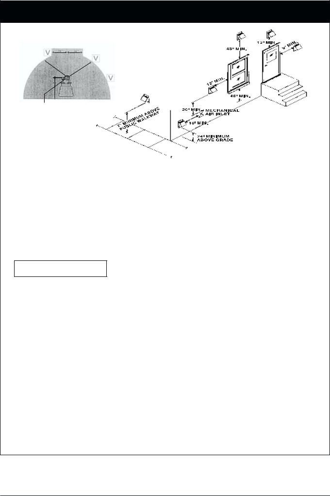
a)The vent terminal of this Power Vent System shall not be less than 7 feet (213cm) above grade when located in areas accessible to public walkways.
b)A vent terminal shall terminate at least 3 feet (91cm) above and a minimum of 10 feet (305cm) horizontally from any (mechanical) air inlet.
c)The vent terminal shall not be within 6 feet (183cm) radius from a gas meter or regulator, and horizontally it must be a minimum of 3 feet (91cm) from the centre line of such regulator.
d)The vent terminal shall be a minimum of 6 feet (182cm) from any combustion air inlet.
e)The vent terminal shall terminate from an opening window, at least 4 feet (122cm) below or below the opening and 12 inches (30cm) horizontally. From a door 1 foot (30cm) above and 9 inches (23cm) horizontally.
f)The vent terminal shall not be less than 3 feet (91cm) from an adjacent building.
g)The vent terminal shall not be less than 2 feet (61cm) above grade.
8 |
6 720 606 599 |
Bosch POWER VENTING SYSTEM
Figure 2
36”
7 |
|
2 |
|
|
” |
36”
72”
REGULATOR VENT
ELECTRICAL WIRING:
1.The electrical contact ratings are as follows:
______ 1/10 HP at 120 VAC
______ 3 Amps (full load) at 120 VA
2.Provide switched plug receptacle to accommodate Bosch grounded plug.
3.Make certain the power source is adequate for the fan motor requirements.
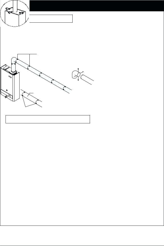
VENT INSTALLATION
1.Choose approved terminal location
2.Cut vent terminal opening through outside wall - Refer to installation instructions supplied with termination.
3.Install vent terminal by fastening from outside with 4 screws and caulking around flange edge. Check that optional flapper moves freely if applicable.
4.Install 4” venting materials and secure all joints with a minimum of four screws for each joint. Please note that wherever possible use continual lengths of pipe to reduce the number of joints.
5.Seal all positive vent pipe and elbow joints between Bosch unit and vent terminal with high temperature silicone and/or hi temperature aluminum tape following manufacturer’s instructions (i.e. always push silicone ahead of nozzle)
6 720 606 599 |
9 |
Bosch POWER VENTING SYSTEM
VENT INSTALLATION (continued)
6.Support venting duct with plumber’s strap (supplied by installer). Solid piping need only be supported every four feet. All horizontal pipe joints must be secured with a minimum of four screws per joint. (See Figure 3)
7.All runs through unheated spaces must be wrapped and insulated with a minimum of 1” insulation.
Figure 3
Vent support hangers (plumber's strapping) should be 4 ft. apart on horizontal runs.
Use 4 screws per joint 
RIGID PIPE
positive pressure
All joints must be sealed with high temperature silicone and high temperature aluminum vent pipe tape
OPERATION AND CHECKING THE DRAFT
All clamped joints on the positive side of the power venter are to be sealed with high temperature silicone.
A. Place Bosch appliance into operation. Follow lighting pilot and operating instructions on Bosch cover.
1.Draw water continuously to activate appliance which will turn on gas burner.
2.CHECKING THE DRAFT. Operate the appliance with cover in place for a minimum of five minutes and check for proper venting, and assure that the combustion products are venting properly, by passing a lighted match flame or smoke taper over the top edge of the Bosch cover and towards draft hood. If the vent is drawing properly, the smoke or match flame will be drawn over the top edge of the Bosch cover and into the draft hood or opening. (see drawing below Checking The Draft)
CHECKING THE DRAFT
NOTE: If smoke is not drawn in then the combustion products are escaping from the relief opening into the room. Under these conditions, the equipment shall not be operated until proper adjustments or repairs are made to provide adequate draft.
3.Check draft spill safety switch by obstructing outside vent terminal and by drawing water. Spill switch should trip and shut off gas supply to Bosch unit. Remove outside obstruction.
4.If spill switch trips allow 5 minutes to reset.
10 |
6 720 606 599 |
Bosch POWER VENTING SYSTEM
B.The Air-Flow Adjustment on the Power Venter is factory set for optimum air flow. Operating at its setting will assure that combustion gases are safely removed to the outside.
MAINTENANCE
Points of inspection are:
1.Motor - Motor must rotate freely.
2.Fan Wheel - Wheel must be clean of dust or any other coating which inhibits rotation or air flow. Remove all foreign material from vent system before operation.
3.Spill Switch - Verify proper spill switch operation by observing Operation Sequence and by temporarily blocking termination outlet.
4.Check Draft - Check for flue gas spillage following steps in the Operation And Checking Draft on page 9.
5.Vent Termination - Inspect to ensure installation and clearances have not been altered or obstructed and that the back draft flapper (when used) movement is free and operational. Note that terminal hood is removable for easy flapper maintenance or replacement.
Hinge
Vent termination hood
Flapper
6 720 606 599 |
11 |

DRIP TRAY
If the water heater is being mounted above a floor of combustible construction the drip tray (shipped loose in the carton with the water heater) must be attached to the bottom of the front cover of the water heater at the time of installation. The drip tray should be attached to the front cover, using screws provided, as shown in Figure 3.
Failure to use drip tray when installing unit above a floor of combustible construction will cause an unsafe condition and possible fire and will be in violation of A.G.A. and C.G.A. certification of the unit.
WATER CONNECTIONS
The BOSCH instantaneous water heaters are provided with two S-bend water connectors/adaptors that must be connected to inlet and outlet connections on water valve assembly, see Figure 4, below.
SCREWS
INCANDESCENT PARTICLE TRAY
Figure 3
Water valve and S-bends, top view
Figure 4
The purpose of the S-bend water connectors/adaptors is to provide threaded water connections that meet standards used in North America, ANSI Standard Taper Pipe Thread (1/2” NPT). The cold water supply should be connected to S-bend attached to inlet of water valve and the hot water connection should be made to S-bend attached to the outlet of water valve.
If plastic piping is to be used, a 1.5 meter (approx. 5 feet) length of metal piping must first be attached to both the cold water inlet and hot water outlet of the water heater.
Note: A shut-off valve should be placed in the cold water supply line to the heater to facilitate servicing the heater.
12 |
6 720 606 599 |
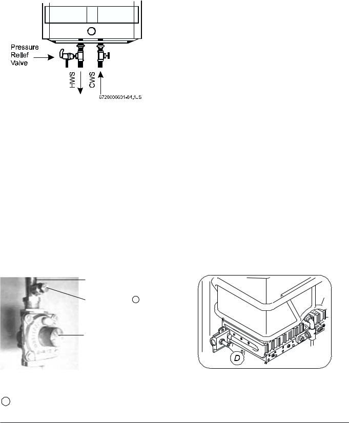
RELIEF VALVE
The listed pressure relief valve supplied must be installed near the hot water outlet at time of installation of the heater. No valve is to be placed between the relief valve and the heater. A drain line must be connected to the relief valve to direct discharge to a safe location. Do not install reducing coupling or any other restriction in the discharge line. The discharge line must be installed so as to allow complete drainage of both the valve and the line. See figure 5.
Figure 5
GAS CONNECTIONS
Before connecting the gas supply to the heater, check heater’s model/rating plate to make sure that the gas on which heater is to operate is the same as specified on the model/rating plate.
The WR430-7.K.. instantaneous water heaters are supplied with a gas pressure regulator that must be installed on the heater before attaching the gas supply line. See figure 6. Failure to install the gas pressure regulator as shown in figure 6 will be a violation of A.G.A. and C.G.A. certification of the unit.
BOSCH water heaters are shipped from the factory with the gas pressure regulators preset for the gas shown on the rating plate to the correct pressure:
•in Canada, for high altitude operation;
•in U.S.A., for standard altitude operation unless specifically marked as a high altitude unit.
GAS INLET PIPE
PRESSURE TAP T
APPLIANCE PRESSURE
REGULATOR
Check to make sure that the gas listed on the rating plate is same as gas listed on the pressure regulator. See PRESSURE REGULATION section of this manual for information regarding gas pressure settings.
Note: Before attaching the gas supply line, be sure that all gas pipe is clean on the inside. To trap any dirt or foreign material in the gas supply line, a drip leg must be incorporated in the piping. The drip leg must be readily accessible and not subject to freezing conditions. Install in accordance with the recommendations of serving gas supplier.
Joint compounds (pipe dope) shall be applied sparingly and only to the male threads of pipe joints. Do not apply compound to the first two threads. The joint compound must be resistant to the action of liquified petroleum gases.
Before placing water heater in operation, check for gas leakage. Soap and water solution, or other material acceptable for this purpose shall be used in locating gas leaks. Matches, candles, lighters, or other ignition sources shall not be used for this purpose.
WARNING
The heater and its individual shutoff valves must be disconnected from the gas supply piping system during any pressure testing of that system at test pressures in excess of 3.45 kPa (1/2 psig).
The water heater, including the pressure regulator provided with it, must not be operated at gas supply pressures in excess of 3.45 kPa (1/2 psig). If overpressure has occurred such as through improper testing of the gas lines or emergency malfunction of the supply system, the gas valve and regulator must be checked for safe operation. Make sure that the outside vent valves are protected against blockage. These are part of the gas supply system, not the water heater. Vent blockage may occur during ice storms.
Figure 7 Gas Burner test point D for measuring burner manifold pressure at full flow and input:
Standard Altitude: 4.58”W.C. Nat Gas, 9.11”W.C. Propane. High Altitude: 3.73”W.C. Nat Gas, 7.27”W.C. Propane.
Figure 7
Figure 6 GAS MANIFOLD PRESSURE TEST POINT
T For measuring correct regulator operating pressure.
6 720 606 599 |
13 |

OPERATING INSTRUCTIONS
WARNING!
If the water heater has been damaged or exposed to fire or sooting, or if any part has been underwater, do not use. If unit has been operated during construction or alterations and exposed to above normal dust levels the heat exchanger should be examined and cleaned regularly. Operation with dust obstructed fins could be a health hazard. Immediately call a qualified service technician to inspect the appliance and to replace any part of the control system and any gas control which has been underwater and to clean the heat exchanger assembly and water valve.
FILLING
Before proceeding with operation of the water heater make sure that the system is filled with water:
•Make sure drain is closed. See figure 8, below.
•Open a nearby hot water faucet to permit the water to fill the heater and piping.
•Close the hot water faucet after the water flows freely and all air has escaped from the system.
The water heater is now ready to be lit.
TO HEAT EXCHANGER
WATER VALVE
LIGHTING AND OPERATING INSTRUCTIONS
1.STOP! Read the safety information above on this lable.
2.The gas valve must be shut off by putting the ON/OFF
switch to position “ ” Wait five (5) minutes to clear out any gas. If you smell gas, STOP! Follow “B” in the safety information above. If you do not smell gas, go to the next step.
3.This water heater is equipped with a safety pilot burner and an automatic ignition control system.
4.Set the ON/OFF switch (flip down cover plate on frontal
panel strip) marked  /
/  to the "
 " position. In this position, the water heater is ready to use. (See Fig. 9).
5.Turn the hot water faucet on the minimum flow rate required to activate the heater. The automatic ignition system first ignites the safety pilot burner which then ignites the main burner in about 4 seconds.
6.The pilot flame will extiguish 10-30 seconds after the burners come on. The burners will remain on until the hot water tap is turned off.
7.Vent fan turns on and off with burner.
NOTE: On a first time initial installation, existence of air in the gas supply line and in the water line may cause some ignition delay. In that case, repeatedly open and close the hot water tap in order to restart the ignition process until all the air has been purged.
FROM HEAT
EXCHANGER
DRAIN PLUG
Figure 8
SERVICE HINT
The screen (strainer) in the water valve, located in the inlet of the water valve, may require occasional cleaning due to foreign material in the water supply. This will restrict the flow of water and may affect heater operation and prolong filling time. To inspect the strainer, close the cold water supply valve ahead of the heater, disconnect the S-bend from the inlet of the water valve and remove strainer from inlet. Clean if required, replace strainer in inlet to the water valve, reconnect S-bend and turn on water supply.
Light the water heater in accordance with the instructions on the Lighting and Operating Plate on the water heater. For your convenience, the instructions are repeated here:
TO TURN OFF GAS TO APPLIANCE
Turn off the manual lever on the gas supply line to the heater and set the ON/OFF switch to the OFF (  ) position.
To operate the heater, set the ON/OFF switch to position “  ”. The switch is located behind the flip down cover plate on the front panel strip.
To shut down the gas to the heater, set the ON/OFF switch to position “  ”.
”.
Figure 9
14 |
6 720 606 599 |
PRESSURE REGULATION
The pressure regulator supplied with the water heater is adjusted to operate on the gas specified on the rating plate and:
•in Canada, is factory preset to deliver gas at the high altitude setting listed on the rating plate and as shown below.
•in the U.S.A., is factory preset to deliver gas at the standard altitude setting listed on the rating plate and as shown below.
The pressure setting of the gas pressure regulator should be checked at installation to assure that the setting is correct for the gas being used and the altitude at which the appliance is installed. See rating plate on the unit, Table 1, below, for proper setting.
In Canada, for a heater being installed at standard altitude (0-2,000 ft above sea level) the manifold pressure should be reset at installation to the value shown on the rating plate, or Table 1, below, for standard altitude.
REGULATOR
SUPPLY TEST
PRESSURE TAP T
ADJUSTABLE
PRESSURE REGULATOR
Figure 10
The gas pressures specified below refer to flow pressure taken at the pressure tap in the gas inlet pipe just above the pressure regulator, (see figure 10) while the heater is operating at full input.
Gas pressures read at burner test point D (see fig. 7) page 13.
Table 1.
Appliance Regulator Pressure Setting
Model |
Type of Gas |
Pressure tap |
Altitude |
||
|
|
||||
kPa |
Inches, W.C. |
||||
|
|
|
|||
|
|
|
|
|
|
|
natural |
1.41 |
5.38 |
standard |
|
|
|
|
|
|
|
WR430-7K |
propane |
2.61 |
9.9 |
(0-2,000 ft.) |
|
|
|
|
|
||
natural |
1.14 |
4.4 |
high* |
||
|
|||||
|
|
|
|
|
|
|
propane |
2.09 |
7.9 |
(2,000-4,500 ft.) |
|
|
|
|
|
|
|
*Note: The high altitude ratings listed are Canadian Gas Association high altitude ratings for the appliances and are only valid in Canada. In the U.S.A. the National Fuel Gas Code, ANSI 1- 1988, recommends for high altitude installations, above 2,000 feet, that the input rate be reduced 4% for each 1,000 feet above sea level.
Your appliance dealer and/or your local gas supplier should be consulted in regard to any high altitude installation. If field adjustment is required it should be performed by a qualified serviceman experienced in such work.
TEMPERATURE REGULATION
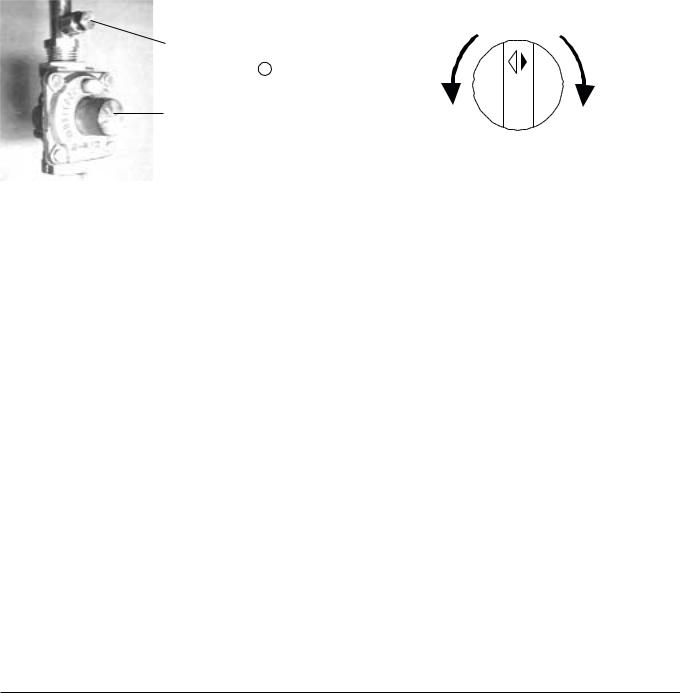
The BOSCH WR430-7K is equipped with a modulating gas valve which adjusts the flow of gas to the main burner in proportion to the water flow rate. Within its heating capacity the WR430-7K attempts to maintain the set temperature rise across the heater. This temperature rise can be set in range of 25°C - to - 50°C (45°F - to - 90°F), by means of the water flow selector. See Figure 11. When the water flow selector is turned to the right hand stop the water heater is set for 50°C (90°F) temperature rise; when the water flow selector is set to the left hand stop it is set for 25°C (45°F) temperature rise.
Temperature Adjustment Knob
Decreases temperature |
Increases temperature |
and increases flow |
and decreases flow |
Figure 11 - Principles of Operation
With the water flow selector turned to its right hand stop position (50°C rise setting) and with an inlet water temperature of 10°C (50°F) the outlet water temperature will be maintained at approximately 60°C (140°F) in the water flow rate range of approximately 2 litres/min. (0.5 U.S. gals./min.) to 9.5 litres/min. (2.5 U.S. gals./min.).
The minimum flow rate for operation, the “Threshold Flow Rate” referred to in the lighting instructions is 2 litres/min (0.5 U.S. gals./min.). If the water flow rate is below this level the main burner will not fire. If the flow rate exceeds 9.5 litres/min (2.5 U.S. gals./min.) the temperature rise aross the heater will decrease in proportion to the rate above this temperature.
HIGH TEMPERATURE LIMIT SWITCH
The BOSCH series instantaneous gas water heaters are equipped with a high temperature limit switch with a set point of approximately 90°C (195°F). If the water temperature at the sensing points exceeds the set point the switch will open, interrupting the safety circuit and stopping gas flow to the pilot and main burner.
Outage as the result of high limit operation indicates that the heater is not functioning properly. The heater should be checked by a qualified serviceman and the reason for the malfunction is corrected.
6 720 606 599 |
15 |
 Loading...