

Page 1
Default Login Details
User’s Guide
NWA1123 Series
802.11 a/b/g/n/ac Hybrid Access Point
LAN IP Address DHCP-assigned
OR
http://192.168.1.2
User Name admin
Password 1234
Version 5.20 Edition 1, 02/2018
Copyright © 2018 Zyxel Communications Corporation
Page 2

IMPO RTANT!
READ CAREFULLY BEFO RE USE.
KEEP THIS GUIDE FO R FUTURE REFERENCE.
This is a User’s Guide for a series of products. Not all products support all firmware features. Screenshots
and graphics in this book may differ slightly from your product due to differences in your product
firmware or your computer operating system. Every effort has been made to ensure that the information
in this manual is accurate.
Re lated Doc um enta tion
•Quick Start Guide
The Quick Start Guide shows how to connect the NWA1123 and access the Web Configurator.
•CLI Reference Guide
The CLI Reference Guide explains how to use the Command-Line Interface (CLI) and CLI commands
to configure the NWA1123.
Note: It is recommended you use the Web Configurator to configure the NWA1123.
• Web Configurator Online Help
Click the help icon in any screen for help in configuring that screen and supplementary information.
•More Information
Go to support.zyxel.c o m to find other information on the NWA1123.
NWA1123 Series User’s Guide
2
Page 3
Doc ume nt Co nve ntions
Wa rnings a nd No tes
These are how warnings and notes are shown in this guide.
Wa rnings tell yo u a bo ut things that c ould ha rm yo u o r your de vice .
Note: Notes tell you other important information (for example, other things you may need to
configure or helpful tips) or recommendations.
Synta x Co nve ntions
• All models in this series may be referred to as the “NWA1123” in this guide.
• Product labels, screen names, field labels and field choices are all in bold font.
• A right angle bracket ( > ) within a screen name denotes a mouse click. For example, C o nfig uratio n >
Ne twork > IP Setting means you first click C onfigura tion in the navigation panel, then the Ne twork sub
menu and finally the IP Setting tab to get to that screen.
Ic o ns Used in Fig ure s
Figures in this guide may use the following generic icons. The NWA1123 icon is not an exact
representation of your device.
NWA1123 Router Switch Internet
Server Desktop Laptop
NWA1123 Series User’s Guide
3
Page 4

Contents Overview
Conte nts O ve rvie w
Introduction ........................................................................................................................................... 12
Sta ndalone Co nfigura tion ................................................................................................................19
Standalone AP Mode .......................................................................................................................... 20
The Web Configurator ......................................................................................................................... 26
Setup Wizard ......................................................................................................................................... 37
Dashboard ............................................................................................................................................ 43
Monitor ................................................................................................................................................... 49
Network ................................................................................................................................................. 63
Wireless ................................................................................................................................................... 69
User ......................................................................................................................................................... 81
AP Profile ................................................................................................................................................ 88
WDS Profile ........................................................................................................................................... 107
Certificates .......................................................................................................................................... 109
System .................................................................................................................................................. 125
Log and Report ................................................................................................................................... 150
File Manager ....................................................................................................................................... 162
Diagnostics .......................................................................................................................................... 173
LEDs ...................................................................................................................................................... 175
Antenna Switch .................................................................................................................................. 177
Reboot ................................................................................................................................................. 179
Shutdown ............................................................................................................................................. 180
Cloud Mana g e me nt .......................................................................................................................181
Cloud Mode ........................................................................................................................................ 182
The Web Configurator ....................................................................................................................... 188
Dashboard .......................................................................................................................................... 192
Network ............................................................................................................................................... 194
Troubleshooting .................................................................................................................................. 198
NWA1123 Series User’s Guide
4
Page 5

Table of Contents
Ta ble o f Conte nts
Doc ume nt Conve ntio ns ......................................................................................................................3
Co nte nts O ve rview .............................................................................................................................4
Ta ble of C o nte nts.................................................................................................................................5
Cha pte r 1
Introduc tio n ........................................................................................................................................12
1.1 Overview ........................................................................................................................................ 12
1.1.1 Management Mode ............................................................................................................. 13
1.1.2 Mode Changing ................................................................................................................... 13
1.1.3 MBSSID .................................................................................................................................... 14
1.1.4 Dual-Radio ............................................................................................................................. 15
1.1.5 Root AP ................................................................................................................................... 16
1.1.6 Repeater ................................................................................................................................ 17
Pa rt I: Sta nda lone Co nfiguration ................................................................... 19
Cha pte r 2
Sta ndalone AP Mo de ........................................................................................................................20
2.1 Overview ........................................................................................................................................ 20
2.2 Ways to Manage the NWA1123 ................................................................................................... 20
2.3 Good Habits for Managing the NWA1123 ................................................................................... 21
2.4 Hardware Connections ................................................................................................................. 21
2.5 LEDs .................................................................................................................................................. 21
2.5.1 NWA1123-AC PRO ................................................................................................................ 21
2.5.2 NWA1123-ACv2 ..................................................................................................................... 23
2.5.3 NWA1123-AC HD ................................................................................................................... 24
2.6 Starting and Stopping the NWA1123 ........................................................................................... 25
Cha pte r 3
The We b Co nfig urator........................................................................................................................26
3.1 Overview ......................................................................................................................................... 26
3.2 Accessing the Web Configurator ................................................................................................. 26
3.3 Navigating the Web Configurator ............................................................................................... 28
3.3.1 Title Bar ................................................................................................................................... 28
3.3.2 Navigation Panel .................................................................................................................. 31
3.3.3 Warning Messages ................................................................................................................ 34
NWA1123 Series User’s Guide
5
Page 6

Table of Contents
3.3.4 Tables and Lists ...................................................................................................................... 34
Cha pte r 4
Setup Wizard .......................................................................................................................................37
4.1 Accessing the Wizard ..................................................................................................................... 37
4.2 Using the Wizard ............................................................................................................................. 37
4.2.1 Step 1 Time Settings .............................................................................................................. 37
4.2.2 Step 2 Password and Uplink Connection ........................................................................... 38
4.2.3 Step 3 Radio ......................................................................................................................... 39
4.2.4 Step 4 SSID ............................................................................................................................. 40
4.2.5 Summary ............................................................................................................................... 42
Cha pte r 5
Dashb o a rd ..........................................................................................................................................43
5.1 Overview ......................................................................................................................................... 43
5.1.1 What You Can Do in this Chapter ....................................................................................... 43
5.2 Dashboard ...................................................................................................................................... 43
5.2.1 CPU Usage ............................................................................................................................. 47
5.2.2 Memory Usage ...................................................................................................................... 48
Cha pte r 6
Mo nitor................................................................................................................................................49
6.1 Overview ......................................................................................................................................... 49
6.1.1 What You Can Do in this Chapter ....................................................................................... 49
6.2 What You Need to Know ............................................................................................................... 49
6.3 Network Status ................................................................................................................................ 50
6.3.1 Port Statistics Graph .............................................................................................................. 52
6.4 Radio List ........................................................................................................................................ 53
6.4.1 AP Mode Radio Information ................................................................................................54
6.5 Station List ....................................................................................................................................... 56
6.6 WDS Link Info ................................................................................................................................... 57
6.7 Detected Device ........................................................................................................................... 58
6.8 View Log .......................................................................................................................................... 60
Cha pte r 7
Ne two rk...............................................................................................................................................63
7.1 Overview ......................................................................................................................................... 63
7.1.1 What You Can Do in this Chapter ....................................................................................... 63
7.2 IP Setting ......................................................................................................................................... 63
7.3 VLAN ................................................................................................................................................ 65
7.4 NCC Discovery ................................................................................................................................ 68
Cha pte r 8
Wire less ...............................................................................................................................................69
NWA1123 Series User’s Guide
6
Page 7

Table of Contents
8.1 Overview ......................................................................................................................................... 69
8.1.1 What You Can Do in this Chapter ....................................................................................... 69
8.1.2 What You Need to Know ..................................................................................................... 70
8.2 AP Management ............................................................................................................................ 70
8.3 Rogue AP ......................................................................................................................................... 73
8.3.1 Add/Edit Rogue/Friendly List ................................................................................................ 75
8.4 Load Balancing .............................................................................................................................. 76
8.4.1 Disassociating and Delaying Connections ........................................................................ 77
8.5 DCS .................................................................................................................................................. 78
8.6 Technical Reference ...................................................................................................................... 79
Cha pte r 9
User......................................................................................................................................................81
9.1 Overview ......................................................................................................................................... 81
9.1.1 What You Can Do in this Chapter ....................................................................................... 81
9.1.2 What You Need To Know ..................................................................................................... 81
9.2 User Summary .................................................................................................................................. 82
9.2.1 Add/Edit User ......................................................................................................................... 82
9.3 Setting ............................................................................................................................................. 84
9.3.1 Edit User Authentication Timeout Settings .......................................................................... 86
Cha pte r 10
AP Pro file .............................................................................................................................................88
10.1 Overview ....................................................................................................................................... 88
10.1.1 What You Can Do in this Chapter ..................................................................................... 88
10.1.2 What You Need To Know ...................................................................................................88
10.2 Radio .............................................................................................................................................. 89
10.2.1 Add/Edit Radio Profile ........................................................................................................ 90
10.3 SSID ................................................................................................................................................ 95
10.3.1 SSID List ................................................................................................................................. 95
10.3.2 Add/Edit SSID Profile ........................................................................................................... 96
10.4 Security List .................................................................................................................................... 99
10.4.1 Add/Edit Security Profile ..................................................................................................... 99
10.5 MAC Filter List .............................................................................................................................. 103
10.5.1 Add/Edit MAC Filter Profile ............................................................................................... 103
10.6 Layer-2 Isolation List .................................................................................................................... 104
10.6.1 Add/Edit Layer-2 Isolation Profile .................................................................................... 106
Cha pte r 11
WDS Pro file ........................................................................................................................................107
11.1 Overview ..................................................................................................................................... 107
11.1.1 What You Can Do in this Chapter ................................................................................... 107
11.2 WDS Profile ................................................................................................................................... 107
NWA1123 Series User’s Guide
7
Page 8

Table of Contents
11.2.1 Add/Edit WDS Profile ........................................................................................................ 108
Cha pte r 12
Ce rtific a te s .......................................................................................................................................109
12.1 Overview ..................................................................................................................................... 109
12.1.1 What You Can Do in this Chapter ................................................................................... 109
12.1.2 What You Need to Know ................................................................................................. 109
12.1.3 Verifying a Certificate ...................................................................................................... 111
12.2 My Certificates ........................................................................................................................... 112
12.2.1 Add My Certificates .......................................................................................................... 113
12.2.2 Edit My Certificates ........................................................................................................... 115
12.2.3 Import Certificates ........................................................................................................... 118
12.3 Trusted Certificates ..................................................................................................................... 119
12.3.1 Edit Trusted Certificates .................................................................................................... 120
12.3.2 Import Trusted Certificates ............................................................................................... 123
12.4 Technical Reference .................................................................................................................. 124
Cha pte r 13
Syste m ...............................................................................................................................................125
13.1 Overview ..................................................................................................................................... 125
13.1.1 What You Can Do in this Chapter ................................................................................... 125
13.2 Host Name ................................................................................................................................... 125
13.3 Date and Time ........................................................................................................................... 126
13.3.1 Pre-defined NTP Time Servers List ..................................................................................... 128
13.3.2 Time Server Synchronization ............................................................................................ 128
13.4 WWW Overview .......................................................................................................................... 129
13.4.1 Service Access Limitations ............................................................................................... 130
13.4.2 System Timeout .................................................................................................................. 130
13.4.3 HTTPS ................................................................................................................................... 130
13.4.4 Configuring WWW Service Control ................................................................................. 131
13.4.5 HTTPS Example ................................................................................................................... 132
13.5 SSH ............................................................................................................................................... 140
13.5.1 How SSH Works .................................................................................................................. 140
13.5.2 SSH Implementation on the NWA1123 ........................................................................... 141
13.5.3 Requirements for Using SSH ..............................................................................................142
13.5.4 Configuring SSH ................................................................................................................. 142
13.5.5 Examples of Secure Telnet Using SSH .............................................................................. 142
13.6 Telnet ........................................................................................................................................... 144
13.7 FTP ................................................................................................................................................ 144
13.8 SNMP ........................................................................................................................................... 145
13.8.1 Supported MIBs ................................................................................................................. 146
13.8.2 SNMP Traps ......................................................................................................................... 147
13.8.3 Configuring SNMP ............................................................................................................. 147
NWA1123 Series User’s Guide
8
Page 9

Table of Contents
13.8.4 Adding or Editing an SNMPv3 User Profile ...................................................................... 148
Cha pte r 14
Lo g and Re port.................................................................................................................................150
14.1 Overview ..................................................................................................................................... 150
14.1.1 What You Can Do In this Chapter .................................................................................. 150
14.2 Email Daily Report ....................................................................................................................... 150
14.3 Log Setting .................................................................................................................................. 152
14.3.1 Log Setting Screen ............................................................................................................ 153
14.3.2 Edit System Log Settings .................................................................................................. 154
14.3.3 Edit Remote Server ........................................................................................................... 158
14.3.4 Active Log Summary ....................................................................................................... 159
Cha pte r 15
File Ma na ge r ....................................................................................................................................162
15.1 Overview ..................................................................................................................................... 162
15.1.1 What You Can Do in this Chapter ................................................................................... 162
15.1.2 What you Need to Know .................................................................................................. 162
15.2 Configuration File ....................................................................................................................... 163
15.2.1 Example of Configuration File Download Using FTP ...................................................... 167
15.3 Firmware Package .................................................................................................................... 168
15.3.1 Example of Firmware Upload Using FTP .......................................................................... 169
15.4 Shell Script ................................................................................................................................... 170
Cha pte r 16
Dia g no stic s .......................................................................................................................................173
16.1 Overview ..................................................................................................................................... 173
16.1.1 What You Can Do in this Chapter ................................................................................... 173
16.2 Diagnostics .................................................................................................................................. 173
Cha pte r 17
LEDs ...................................................................................................................................................175
17.1 Overview ..................................................................................................................................... 175
17.1.1 What You Can Do in this Chapter ................................................................................... 175
17.2 Suppression Screen .................................................................................................................. 175
17.3 Locator Screen .......................................................................................................................... 176
Cha pte r 18
Ante nna Switc h ................................................................................................................................177
18.1 Overview ..................................................................................................................................... 177
18.1.1 What You Need To Know ................................................................................................. 177
18.2 Antenna Switch Screen ............................................................................................................. 177
NWA1123 Series User’s Guide
9
Page 10

Table of Contents
Cha pte r 19
Re boo t...............................................................................................................................................179
19.1 Overview ..................................................................................................................................... 179
19.1.1 What You Need To Know ................................................................................................. 179
19.2 Reboot ......................................................................................................................................... 179
Cha pte r 20
Shutdo wn ..........................................................................................................................................180
20.1 Overview ..................................................................................................................................... 180
20.1.1 What You Need To Know ................................................................................................. 180
20.2 Shutdown ..................................................................................................................................... 180
Pa rt II: C loud Ma na g e m e nt ......................................................................... 181
Cha pte r 21
Cloud Mode .....................................................................................................................................182
21.1 Overview .................................................................................................................................... 182
21.2 Ways to Manage the NWA1123 ............................................................................................... 182
21.3 Good Habits for Managing the NWA1123 ............................................................................... 183
21.4 Hardware Connections ............................................................................................................. 183
21.5 LEDs .............................................................................................................................................. 183
21.5.1 NWA1123-AC PRO ............................................................................................................ 183
21.5.2 NWA1123-ACv2 ................................................................................................................. 185
21.5.3 NWA1123-AC HD ............................................................................................................... 186
Cha pte r 22
The We b Co nfig urator......................................................................................................................188
22.1 Overview ..................................................................................................................................... 188
22.2 Access .......................................................................................................................................... 188
22.3 Navigating the Web Configurator ...........................................................................................189
22.3.1 Title Bar ............................................................................................................................... 189
22.3.2 Navigation Panel .............................................................................................................. 190
22.3.3 Warning Messages ............................................................................................................ 191
Cha pte r 23
Dashb o a rd ........................................................................................................................................192
23.1 Overview ..................................................................................................................................... 192
23.1.1 What You Can Do in this Chapter ................................................................................... 192
23.2 Dashboard .................................................................................................................................. 192
Cha pte r 24
Ne two rk.............................................................................................................................................194
NWA1123 Series User’s Guide
10
Page 11

Table of Contents
24.1 Overview ..................................................................................................................................... 194
24.1.1 What You Can Do in this Chapter ................................................................................... 194
24.2 IP Setting ..................................................................................................................................... 194
24.3 VLAN ............................................................................................................................................ 196
Cha pte r 25
Tro uble shoo ting ................................................................................................................................198
25.1 Overview ..................................................................................................................................... 198
25.2 Power, Hardware Connections, and LED ................................................................................ 198
25.3 NWA1123 Access and Login ..................................................................................................... 199
25.4 Internet Access ........................................................................................................................... 200
25.5 Wireless Connections ................................................................................................................. 202
25.6 Resetting the NWA1123 ............................................................................................................. 205
25.7 Getting More Troubleshooting Help .........................................................................................206
Appendix A Importing Certificates ............................................................................................... 207
Appendix B IPv6............................................................................................................................... 220
Appendix C Customer Support ..................................................................................................... 228
Appendix D Legal Information ...................................................................................................... 234
Inde x .................................................................................................................................................243
NWA1123 Series User’s Guide
11
Page 12

1.1 O ve rvie w
This User’s Guide covers the following models: NWA1123-ACv2, NWA1123-AC PRO, and NWA1123-AC
HD. Your NWA1123 is a wireless AP (Access Point). It extends the range of your existing wired network
without additional wiring, providing easy network access to mobile users.
Table 1 NWA1123 Series Comparison Table
FEA TURES NWA1123- A C V2 NWA 1123-AC PRO NWA 1123-AC HD
Supported Wireless
Standards
Supported Frequency
Bands
Available Security Modes None
Number of SSID Profiles 64 64 64
Number of Wireless Radios 2 2 2
Rogue APs Detection Yes Yes Yes
WDS (Wireless Distribution
System) - Root AP &
Repeater Modes
Layer-2 Isolation Yes Yes Yes
Internal Antennas Yes Yes Yes
Antenna Switch No Yes No
Power Detection No No Yes
LED Suppression Yes Yes Yes
LED Locator No Yes Yes
Nebula Cloud
Management
Maximum number of log
messages
C HAPTER 1
Introduc tion
IEEE 802.11a
IEEE 802.11b
IEEE 802.11g
IEEE 802.11n
IEEE 802.11ac
2.4 GHz
5 GHz
WEP
WPA2
WPA2-MIX
WPA2-PSK
WPA2-PSK-MIX
Yes Yes No
Yes Yes Yes
512 event logs or 1024 debug logs
IEEE 802.11a
IEEE 802.11b
IEEE 802.11g
IEEE 802.11n
IEEE 802.11ac
2.4 GHz
5 GHz
None
WEP
WPA2
WPA2-MIX
WPA2-PSK
WPA2-PSK-MIX
IEEE 802.11a
IEEE 802.11b
IEEE 802.11g
IEEE 802.11n
IEEE 802.11ac
2.4 GHz
5 GHz
None
WEP
WPA2
WPA2-MIX
WPA2-PSK
WPA2-PSK-MIX
You can set the NWA1123 to operate in either standalone AP or managed AP mode. When the
NWA1123 is in standalone AP mode, it can serve as a normal AP, or even as a root AP or a wireless
repeater to establish wireless links with other APs in a WDS (Wireless Distribution System). A WDS is a
wireless connection between two or more APs.
NWA1123 Series User’s Guide
12
Page 13

Your NWA1123’s business-class reliability, SMB features, and centralized wireless management make it
ideally suited for advanced service delivery in mission-critical networks. It uses Multiple BSSID and VLAN
to provide simultaneous independent virtual APs. Additionally, innovations in roaming technology and
QoS features eliminate voice call disruptions.
The NWA1123 controls network access with Media Access Control (MAC) address filtering, and rogue
Access Point (AP) detection. It also provides a high level of network traffic security, supporting IEEE
802.1x, Wi-Fi Protected Access 2 and Wired Equivalent Privacy (WEP) data encryption.
Your NWA1123 is easy to install, configure and use. The embedded Web-based configurator enables
simple, straightforward management and maintenance. See the Quick Start Guide for how to make
hardware connections.
1.1.1 Manage me nt Mode
The NWA1123 is a hybrid AP and can work either in standalone AP mode or in managed AP mode
(cloud management mode).
Sta ndalone AP
By default, the NWA1123 serves as a normal AP and is to be configured using its built-in web configurator
or CLI (Command Line Interface), See
configurator screens.
Chapter 1 Introduction
Chapter 2 on page 20 for detailed information about the web
Ne bula Cloud Ma nag e me nt
In this mode, you can manage and monitor the NWA1123 through the Zyxel Nebula cloud-based
network management system. See the NCC (Nebula Control Center) User’s Guide for how to configure
Nebula managed devices. See
setting or manually set its IP address.
1.1.2 Mode C ha ng ing
This section describes how to change the NWA1123’s management mode.
From Sta nda lo ne to C lo ud
To manage your NWA1123 via the Zyxel NCC, connect the NWA1123 to the Internet and register it to a
site and organization in the NCC (http://nebula.zyxel.com) first using its serial number and MAC address
or its QR code. The serial number, MAC address and QR code can be found in the web configurator
dashboard or the label on the device. See the corresponding Quick Start Guide for how to do hardware
connections and device registration.
Note: The NWA1123 goes into cloud management mode automatically after it can access
the NCC through the specified proxy server (if any) and is successfully registered in the
NCC. Its login password and wireless settings are then overwritten with what you have
configured in the NCC.
Chapter 21 on page 182 if you want to change the NWA1123’s VLAN
NWA1123 Series User’s Guide
13
Page 14

From Cloud to Sta nda lone
To return to the default standalone AP mode, just click Unre gister to remove the NWA1123 from the
organization in the NCC. The NWA1123 will reboot and restore the factory default settings.
1.1.3 MBSSID
A Basic Service Set (BSS) is the set of devices forming a single wireless network (usually an access point
and one or more wireless clients). The Service Set IDentifier (SSID) is the name of a BSS. In Multiple BSS
(MBSSID) mode, the NWA1123 provides multiple virtual APs, each forming its own BSS and using its own
individual SSID profile.
You can configure multiple SSID profiles, and have all of them active at any one time.
You can assign different wireless and security settings to each SSID profile. This allows you to
compartmentalize groups of users, set varying access privileges, and prioritize network traffic to and
from certain BSSs.
To the wireless clients in the network, each SSID appears to be a different access point. As in any wireless
network, clients can associate only with the SSIDs for which they have the correct security settings.
Chapter 1 Introduction
For example, you might want to set up a wireless network in your office where Internet telephony (VoIP)
users have priority. You also want a regular wireless network for standard users, as well as a ‘guest’
wireless network for visitors. In the following figure, Vo IP_SSID users have QoS priority, SSID01 is the wireless
network for standard users, and G ue st_SSID is the wireless network for guest users. In this example, the
guest user is forbidden access to the wired Land Area Network (LAN) behind the AP and can access
only the Internet.
NWA1123 Series User’s Guide
14
Page 15
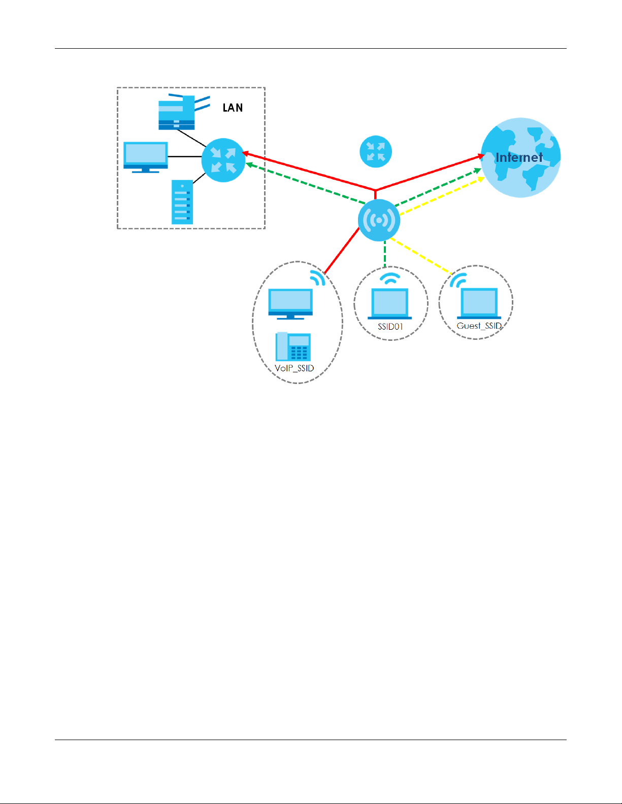
Figure 1 Multiple BSSs
Chapter 1 Introduction
1.1.4 Dual- Ra dio
Some of the NWA1123 models are equipped with dual wireless radios. This means you can configure two
different wireless networks to operate simultaneously.
Note: A different channel should be configured for each WLAN interface to reduce the
effects of radio interference.
You could use the 2.4 GHz band for regular Internet surfing and downloading while using the 5 GHz
band for time sensitive traffic like high-definition video, music, and gaming.
NWA1123 Series User’s Guide
15
Page 16
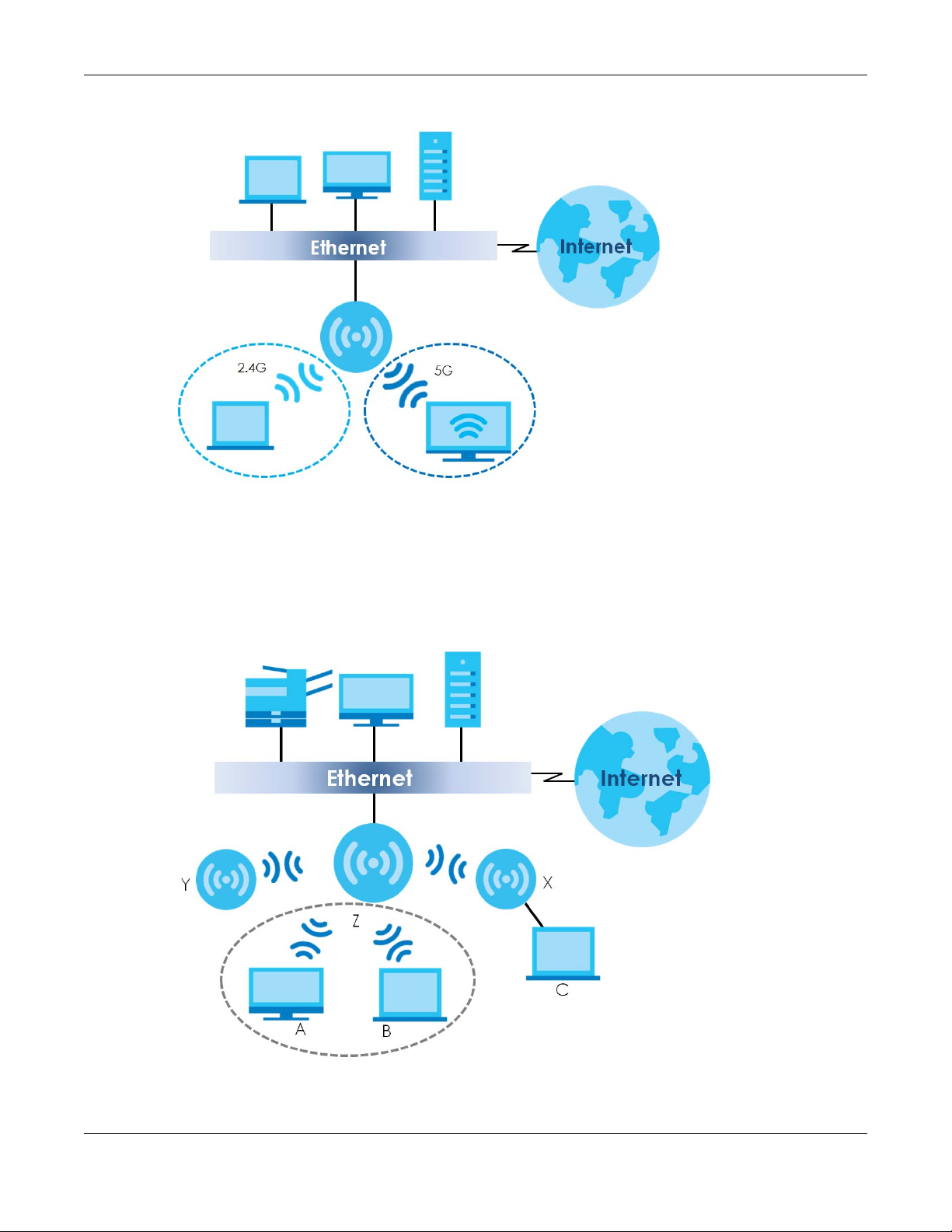
Figure 2 Dual-Radio Application
Chapter 1 Introduction
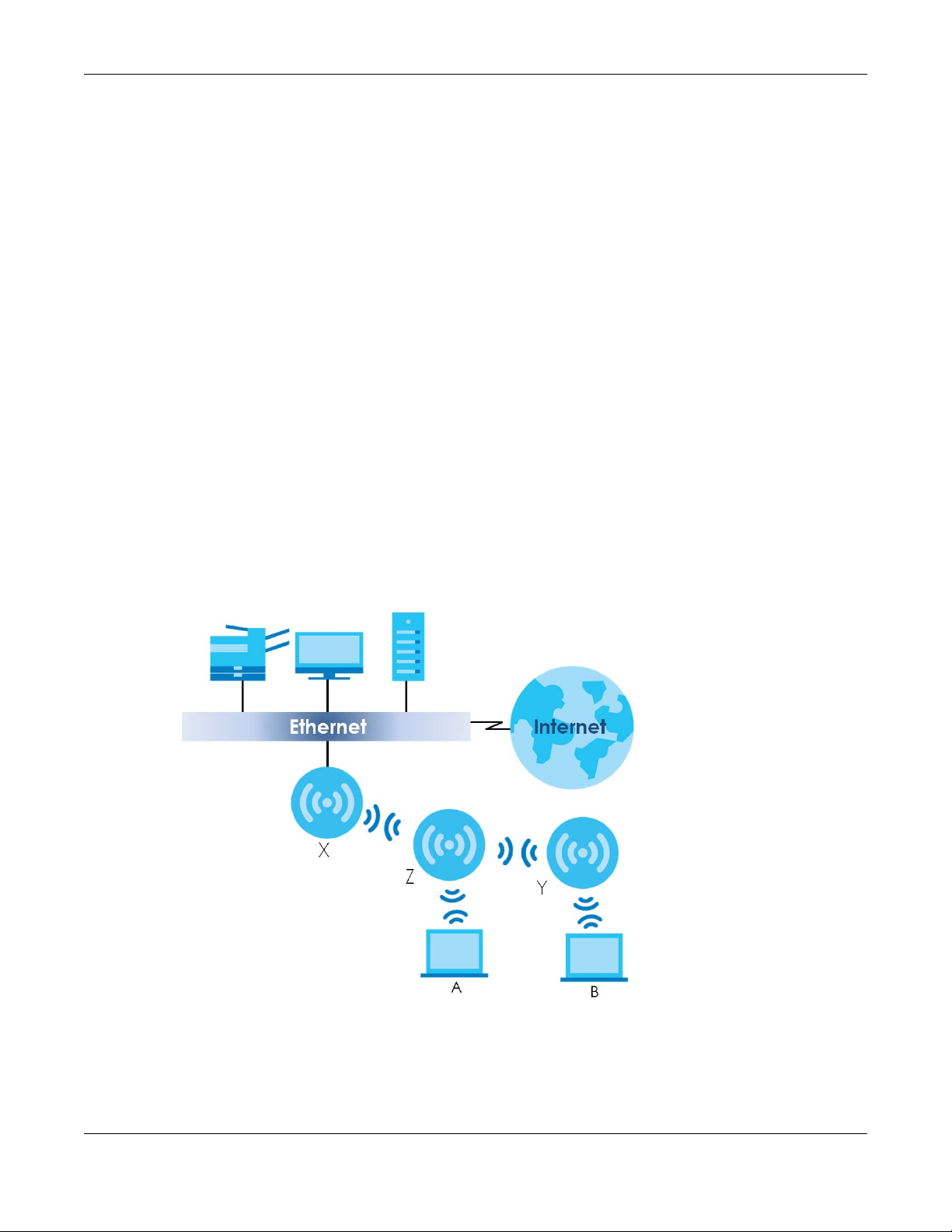
1.1.5 Roo t AP
In Root AP mode, the NWA1123 (Z) can act as the root AP in a wireless network and also allow repeaters
(X and Y) to extend the range of its wireless network at the same time. In the figure below, both clients A,
B and C can access the wired network through the root AP.
Figure 3 Root AP Application
NWA1123 Series User’s Guide
16
Page 17
On the NWA1123 in Root AP mode, you can have multiple SSIDs active for regular wireless connections
and one SSID for the connection with a repeater (repeater SSID). Wireless clients can use either SSID to
associate with the NWA1123 in Root AP mode. A repeater must use the repeater SSID to connect to the
NWA1123 in Root AP mode.
When the NWA1123 is in Root AP mode, repeater security between the NWA1123 and other repeater is
independent of the security between the wireless clients and the AP or repeater. When repeater
security is enabled, both APs and repeaters must use the same pre-shared key. See
70 and Section 11.2 on page 107 for more details.
Unless specified, the term “security settings” refers to the traffic between the wireless clients and the AP.
At the time of writing, repeater security is compatible with the NWA1123 only.
1.1.6 Re pe a ter
The NWA1123 can act as a wireless network repeater to extend a root AP’s wireless network range, and
also establish wireless connections with wireless clients.
Using Repeater mode, your NWA1123 can extend the range of the WLAN. In the figure below, the
NWA1123 in Repeater mode (Z) has a wireless connection to the NWA1123 in Root AP mode (X) which is
connected to a wired network and also has a wireless connection to another NWA1123 in Repeater
mode (Y) at the same time. Z and Y act as repeaters that forward traffic between associated wireless
clients and the wired LAN. Clients A and B access the AP and the wired network behind the AP through
repeaters Z and Y.
Chapter 1 Introduction
Section 8.2 on page
Figure 4 Repeater Application
When the NWA1123 is in Repeater mode, repeater security between the NWA1123 and other repeater is
independent of the security between the wireless clients and the AP or repeater. When repeater
security is enabled, both APs and repeaters must use the same pre-shared key. See
and Section 11.2 on page 107 for more details.
70
Section 8.2 on page
NWA1123 Series User’s Guide
17
Page 18

Chapter 1 Introduction
Once the security settings of peer sides match one another, the connection between devices is made.
At the time of writing, repeater security is compatible with the NWA1123 only.
NWA1123 Series User’s Guide
18
Page 19

PART I
Sta nda lone
Config uration
19
Page 20
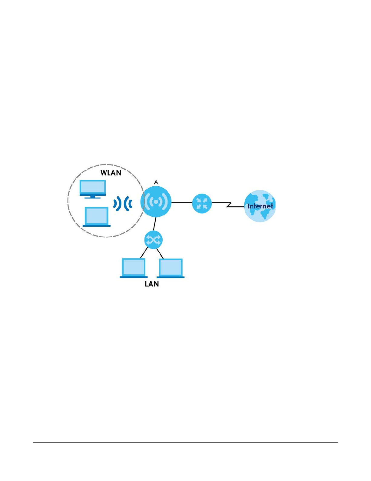
2.1 O ve rvie w
The NWA1123 extends the range of your existing wired network without additional wiring, providing easy
network access to mobile users. You can set up a wireless network with other IEEE 802.11a/b/g/n/ac
compatible devices. The NWA1123 is able to function both 2.4GHz and 5GHz networks at the same time.
Wireless clients can connect to the NWA1123 (A) to access network resources.
C HAPTER 2
Sta nda lone AP Mode
2.2 Wa ys to Ma nag e the NWA1123
You can use the following ways to manage the NWA1123.
We b Co nfig urator
The Web Configurator allows easy NWA1123 setup and management using an Internet browser. This
User’s Guide provides information about the Web Configurator.
Co mma nd- Line Interfac e (CLI)
The CLI allows you to use text-based commands to configure the NWA1123. You can access it using
remote management (for example, SSH or Telnet). See the Command Reference Guide for more
information.
NWA1123 Series User’s Guide
20
Page 21

Chapter 2 Standalone AP Mode
File Tra nsfer Pro to c o l (FTP)
This protocol can be used for firmware upgrades and configuration backup and restore.
Sim ple Ne twork Ma na g e m e nt Protoc ol (SNMP)
The NWA1123 can be monitored by an SNMP manager. See the SNMP chapter in this User’s Guide.
2.3 G ood Habits fo r Ma na g ing the NWA1123
Do the following things regularly to make the NWA1123 more secure and to manage it more effectively.
• Change the password often. Use a password that’s not easy to guess and that consists of different
types of characters, such as numbers and letters.
• Write down the password and put it in a safe place.
• Back up the configuration (and make sure you know how to restore it). Restoring an earlier working
configuration may be useful if the device becomes unstable or even crashes. If you forget your
password, you will have to reset the NWA1123 to its factory default settings. If you backed up an
earlier configuration file, you won’t have to totally re-configure the NWA1123; you can simply restore
your last configuration.
2.4 Hardware Conne c tions
See your Quick Start Guide for information on making hardware connections.
2.5 LEDs
The LEDs of your NWA1123 can be controlled by using the Suppression feature such that the LEDs stay lit
(ON) or OFF after the device is ready.
Following are LED descriptions for the NWA1123 series models.
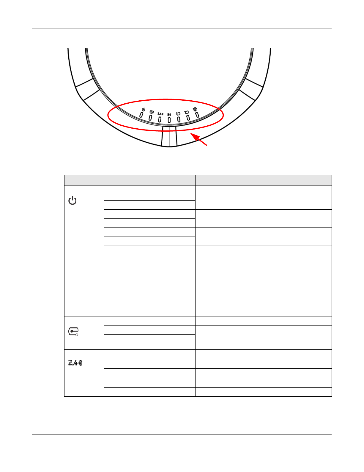
2.5.1 NWA1123- AC PRO
The LEDs will stay ON when the NWA1123-AC PRO is ready. You can change this setting in the
Ma intena nc e > LEDs > Suppre ssio n screen.
NWA1123 Series User’s Guide
21
Page 22
Chapter 2 Standalone AP Mode
Figure 5 NWA1123-AC PRO LEDs
The following table describes the LEDs.
Table 2 NWA1123-AC PRO LEDs
LED CO LO R STATUS DESCRIPTIO N
PWR/SYS Red Slow Blinking (On for 1s,
Off for 1s)
Green On
Red Off The NWA1123 is ready for use.
Green On
Red On There is system error and the NWA1123 cannot boot up,
Green Off
Red Fast Blinking (On for
50ms, Off for 50ms)
Green Off
Red Slow Blinking (Blink for 3
times, Off for 3s)
Green Off
Red Off The wireless module of the NWA1123 is disabled or failed.
Green Slow Blinking (On for 1s,
Off for 1s)
Management Green Off The NWA1123 is in standalone mode.
Green On The NWA1123 is in cloud management mode.
Amber Slow Blinking (On for 1s,
Off for 1s)
WLAN Green On The antenna switch is set to “Ceiling” for the radio.
Amber On The antenna switch is set to “Wall” for the radio.
Off The 2.4 GHz WLAN is not active.
The NWA1123 is booting up.
or the NWA1123 suffered a system failure.
The NWA1123 is doing firmware upgrade.
The Uplink port is disconnected.
The 2.4 GHz WLAN is active.
The 2.4 GHz WLAN is active.
NWA1123 Series User’s Guide
22
Page 23
Chapter 2 Standalone AP Mode
Table 2 NWA1123-AC PRO LEDs (continued)
LED C OLO R STATUS DESCRIPTIO N
WLAN Green On The antenna switch is set to “Ceiling” for the radio.
The 5 GHz WLAN is active.
Amber On The antenna switch is set to “Wall” for the radio.
The 5 GHz WLAN is active.
Off The 5 GHz WLAN is not active.
UPLINK Amber/
Green
LAN Amber/
Green
Locator White Blinking The Locator is activated and will show the actual location
On Amber - The port is operating as a 100-Mbps connection.
Green - The port is operating as a Gigabit connection
(1000 Mbps).
Blinking The NWA1123 is sending/receiving data through the port.
Off The port is not connected.
On Amber - The port is operating as a 100-Mbps connection.
Green - The port is operating as a Gigabit connection
(1000 Mbps).
Blinking The LAN port is sending/receiving data through the port.
Off The LAN port is not connected.
of the NWA1123 between several devices in the network.
Off The Locator function is off.
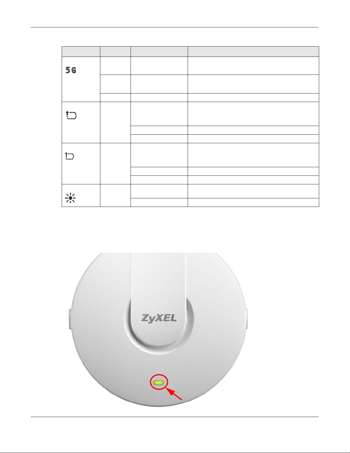
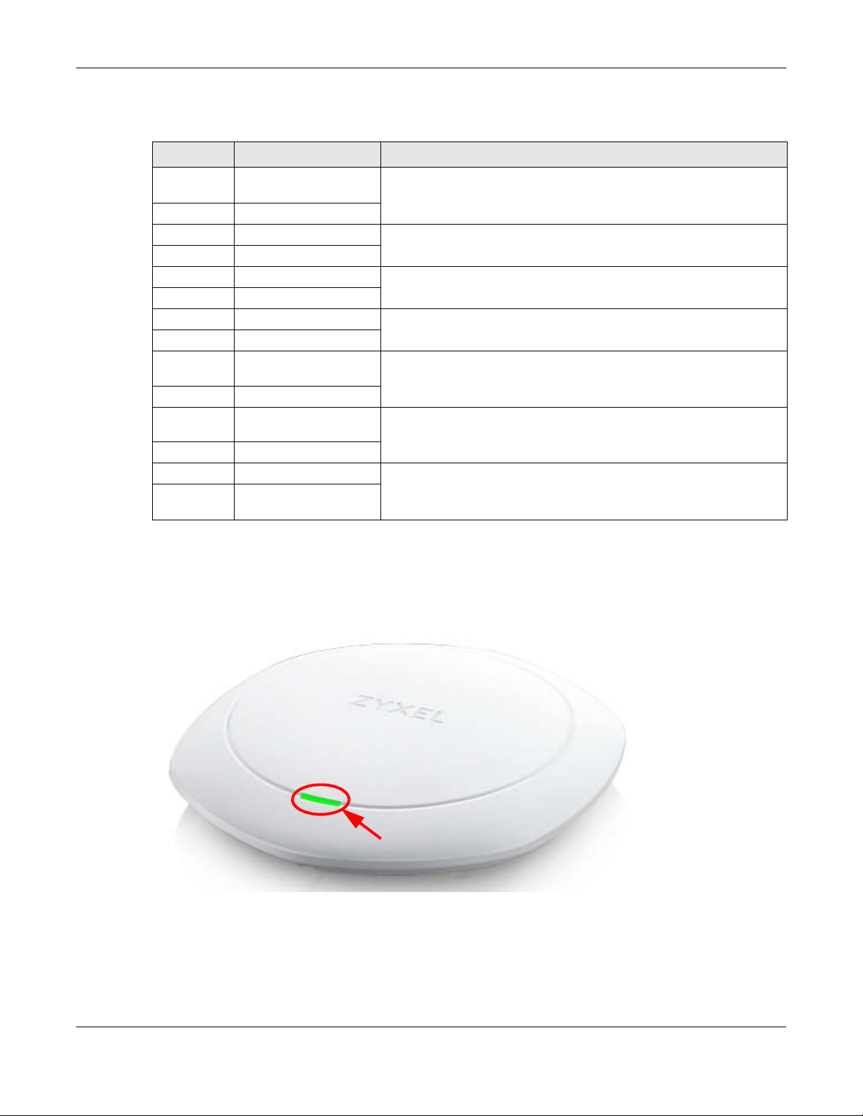
2.5.2 NWA1123- AC v2
The following are the LED descriptions for your NWA1123-ACv2.
Figure 6 NWA1123-ACv2 LED
NWA1123 Series User’s Guide
23
Page 24
Chapter 2 Standalone AP Mode
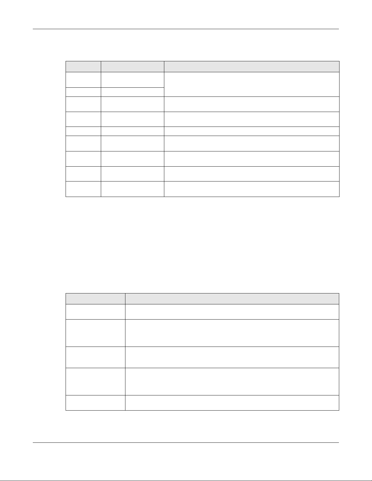
The following are the LED descriptions for your NWA1123.
Table 3 NWA1123-ACv2 LED
COLO R STATUS DESCRIPTION
Amber Slow Blinking (On for 1s,
Off for 1s)
Green On
Amber Off The NWA1123 is ready for use.
Green On
Amber Off The NWA1123’s wireless interface is activated.
Green On
Amber On The NWA1123 failed to boot up or is experience system failure.
Green Off
Amber Fast Blinking (On for
50ms, Off for 50ms)
Green Off
Amber Slow Blinking (Blink for 3
times, Off for 3s)
Green Off
Amber Off The wireless LAN is disabled or fails.
Green Slow Blinking (On for 1s,
Off for 1s)
The NWA1123 is booting up.
The NWA1123 is undergoing firmware upgrade.
The Uplink port is disconnected.
2.5.3 NWA1123- AC HD
The following are the LED descriptions for your NWA1123-AC HD.
Figure 7 NWA1123-AC HD LED
NWA1123 Series User’s Guide
24
Page 25
Chapter 2 Standalone AP Mode
The following are the LED descriptions for your NWA1123.
Table 4 NWA1123-AC HD LED
COLO R STATUS DESCRIPTION
Amber Slow Blinking (On for 1s,
Off for 1s)
Green On
Green On The NWA1123 is ready for use, the NWA1123’s wireless interface is
Bright Blue On The NWA1123’s wireless interface is activated, but there are no wireless
Red On The NWA1123 failed to boot up or is experience system failure.
Red Fast Blinking (On for
50ms, Off for 50ms)
Red Slow Blinking (blink for 3
times, Off for 3s)
Green Slow Blinking (blink for 1
time, Off for 1s)
Blue Slow Blinking (blink for 1
time, Off for 1s)
The NWA1123 is booting up.
activated, and/or wireless clients are connected to the NWA1123.
clients connected.
The NWA1123 is undergoing firmware upgrade.
The Uplink port is disconnected.
The wireless LAN is disabled or fails.
The NWA1123 is checking for an available 5GHz channel.
2.6 Sta rting a nd Sto pping the NWA1123
Here are some of the ways to start and stop the NWA1123.
Alwa ys use Ma inte nanc e > Shutdown o r the shutdown c omm and
be fo re you turn off the NWA1123 o r re mo ve the po we r. No t doing so c an
c a use the firm wa re to be c om e c o rrupt.
Table 5 Starting and Stopping the NWA1123
METHOD DESCRIPTION
Turning on the power A cold start occurs when you turn on the power to the NWA1123. The NWA1123 powers
Rebooting the
NWA1123
Using the RESET button If you press the RESET button on the back of the NWA1123, the NWA1123 sets the
Clicking Ma inte na nc e
> Shutd o wn >
Shutd o wn or using the
shutdown command
Disconnecting the
power
up, checks the hardware, and starts the system processes.
A warm start (without powering down and powering up again) occurs when you use the
Re bo ot button in the Re bo ot screen or when you use the reboot command. The
NWA1123 writes all cached data to the local storage, stops the system processes, and
then does a warm start.
configuration to its default values and then reboots. See
more information.
Clicking Ma inte nanc e > Shutdo wn > Shutdown or using the shutdown command writes all
cached data to the local storage and stops the system processes. Wait for the device to
shut down and then manually turn off or remove the power. It does not turn off the
power.
Power off occurs when you turn off the power to the NWA1123. The NWA1123 simply turns
off. It does not stop the system processes or write cached data to local storage.
Section 25.6 on page 205 for
The NWA1123 does not stop or start the system processes when you apply configuration files or run shell
scripts although you may temporarily lose access to network resources.
NWA1123 Series User’s Guide
25
Page 26
The We b Config ura tor
3.1 O ve rvie w
The NWA1123 Web Configurator allows easy management using an Internet browser. Browsers
supported are:
• Firefox 36.0.1 or later
• Chrome 41.0 or later
• IE 10 or later
The recommended screen resolution is 1024 x 768 pixels and higher.
3.2 Ac c e ssing the We b C onfigurator
C HAPTER 3
1 Make sure your NWA1123 is working in standalone AP mode (see Section 1.1.1 on page 13) and
hardware is properly connected. See the Quick Start Guide.
2 If the NWA1123 and your computer are not connected to a DHCP server, make sure your computer’s IP
address is in the range between "192.168.1.3" and "192.168.1.254".
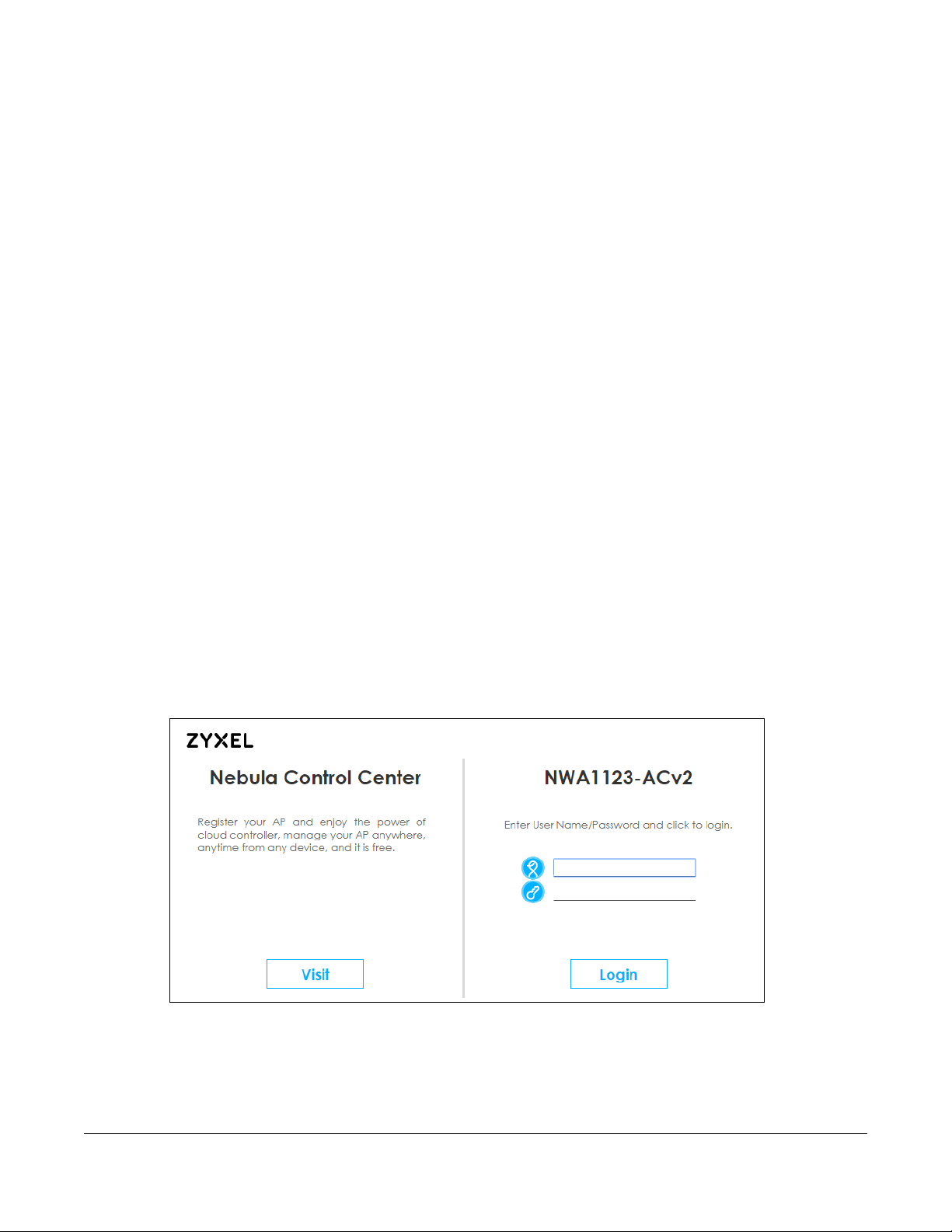
3 Browse to the NWA1123’s DHCP-assigned IP address or http://192.168.1.2. The Log in screen appears.
4 Enter the user name (default: “admin”) and password (default: “1234”). Click Lo g in.
When the NWA1123 is connected to the Internet, a Visit button will also display. Click the button to open
the NCC web site login page in a new tab or window.
NWA1123 Series User’s Guide
26
Page 27
Chapter 3 The Web Configurator
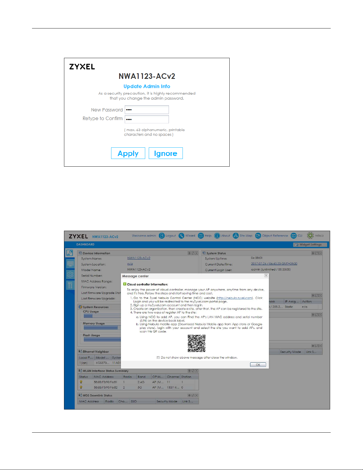
5 If you logged in using the default user name and password, the Upd a te A d min Info screen appears.
Otherwise, the dashboard appears.
The Upda te Ad m in Info screen appears every time you log in using the default user name and default
password. If you change the password for the default user account, this screen does not appear
anymore.
6 Each time you log into the web configurator, a Me ssa ge c e nte r screen will pop up showing the QR
code of the NWA1123. Use the Zyxel Ne bula Mobile app to scan the QR code. The NWA1123 will be
registered and assigned to an existing site/organization in the NCC automatically. Click OK to close the
screen,
NWA1123 Series User’s Guide
27
Page 28
Chapter 3 The Web Configurator
A
C
B
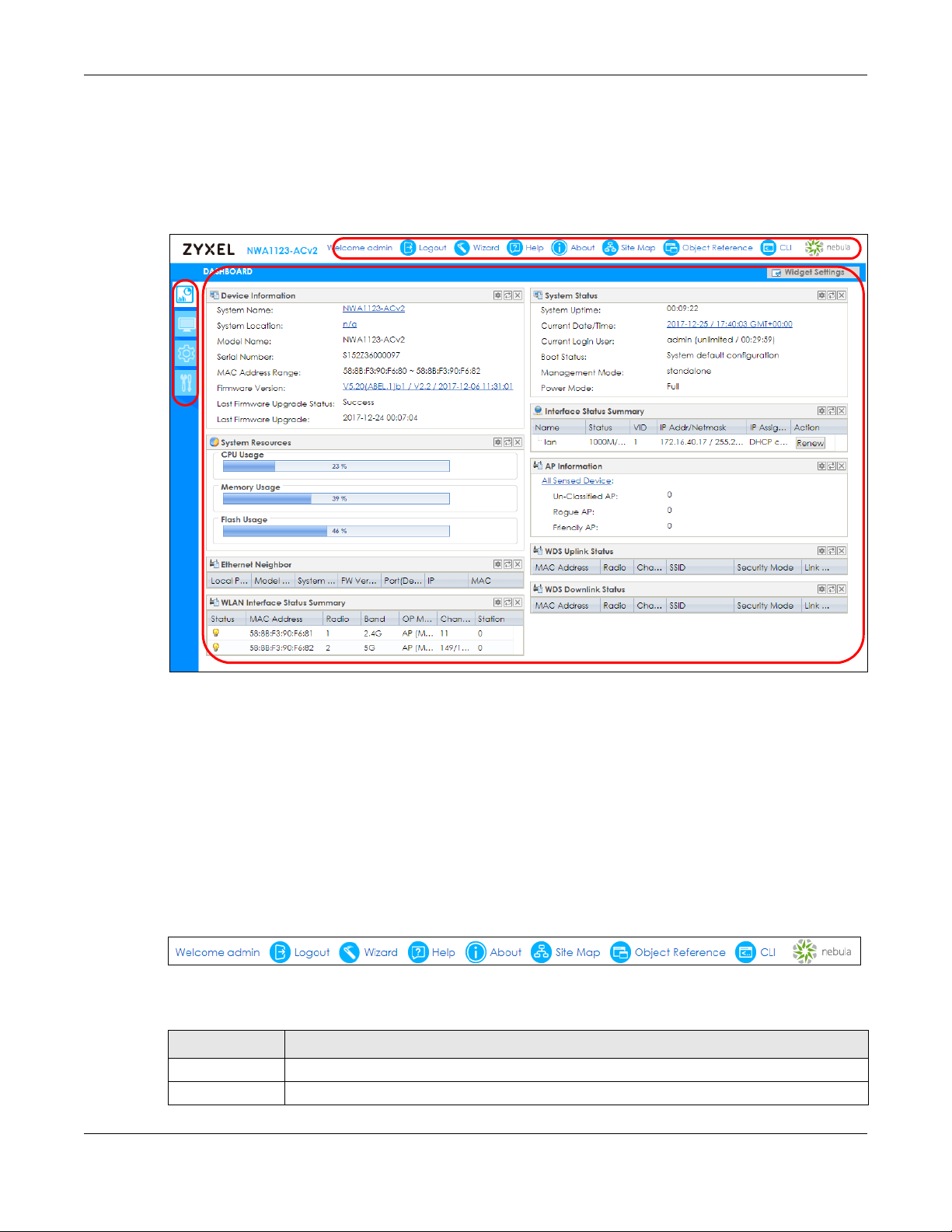
3.3 Navig ating the We b Config ura tor
The following summarizes how to navigate the web configurator from the Dashb o a rd screen. This guide
uses the NWA1123-ACv2 screens as an example. The screens may vary slightly for different models.
Figure 8 The Web Configurator’s Main Screen
The Web Configurator’s main screen is divided into these parts:
• A - Title Bar
• B - Navigation Panel
• C - Main Window
3.3.1 Title Ba r
The title bar provides some useful links that always appear over the screens below, regardless of how
deep into the Web Configurator you navigate.
Figure 9 Title Bar
The icons provide the following functions.
Table 6 Title Bar: Web Configurator Icons
LABEL DESCRIPTION
Logout Click this to log out of the Web Configurator.
Wizard Click this to open the wizard. See
Chapter 4 on page 37 for more information.
NWA1123 Series User’s Guide
28
Page 29
Chapter 3 The Web Configurator
Table 6 Title Bar: Web Configurator Icons (continued)
LABEL DESCRIPTION
Help Click this to open the help page for the current screen.
About Click this to display basic information about the NWA1123.
Site Map Click this to see an overview of links to the Web Configurator screens.
Object
Reference
CLI Click this to open a popup window that displays the CLI commands sent by the Web
nebula Click this to open the NCC web site login page in a new tab or window.
Click this to open a screen where you can check which configuration items reference an
object.
Configurator.
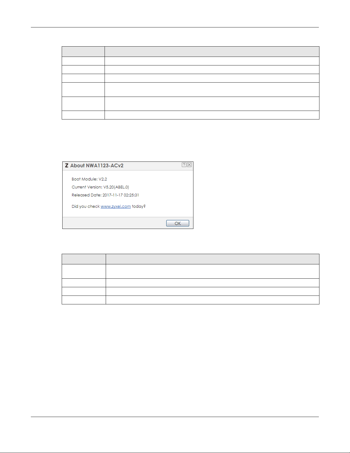
Abo ut
Click Ab o ut to display basic information about the NWA1123.
Figure 10 About
The following table describes labels that can appear in this screen.
Table 7 About
LABEL DESCRIPTIO N
Boot Module This shows the version number of the software that handles the booting process of the
NWA1123.
Current Version This shows the firmware version of the NWA1123.
Released Date This shows the date (yyyy-mm-dd) and time (hh:mm:ss) when the firmware is released.
OK Click this to close the screen.
Site Map
Click Site MA P to see an overview of links to the Web Configurator screens. Click a screen’s link to go to
that screen.
NWA1123 Series User’s Guide
29
Page 30
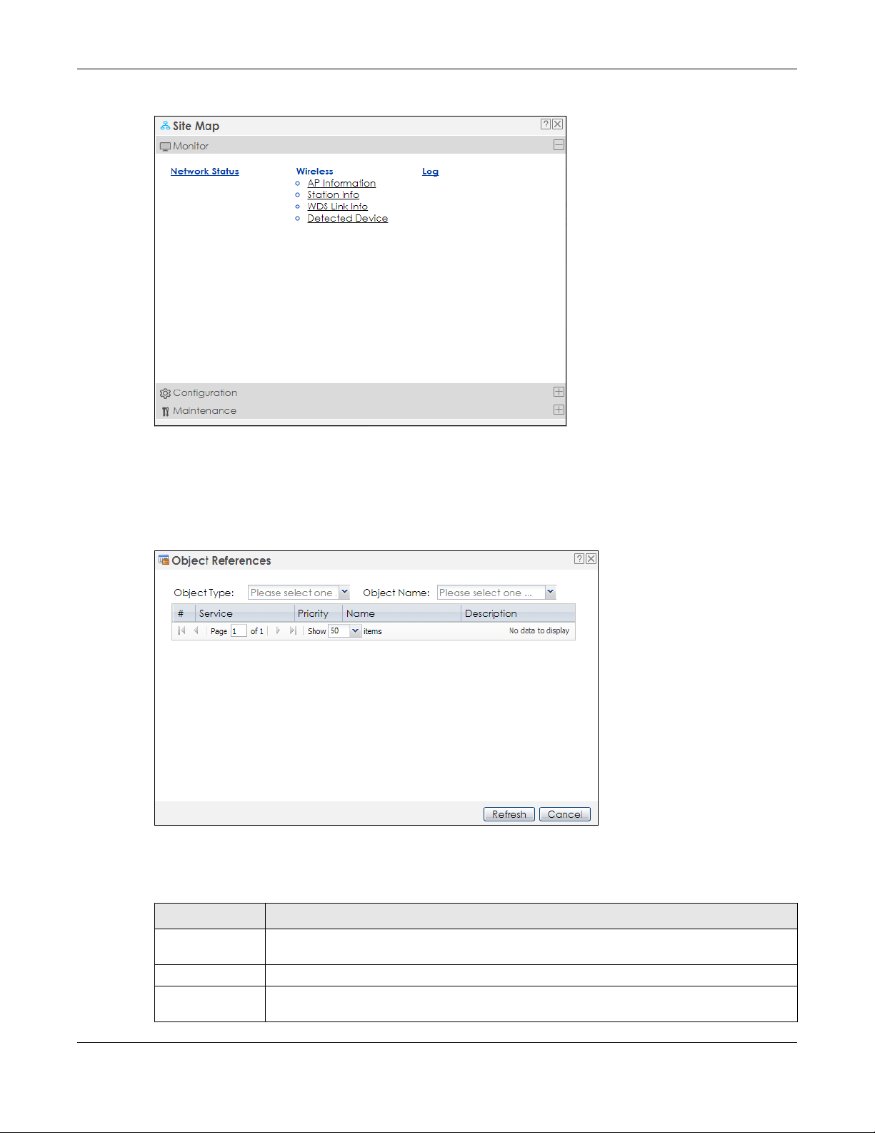
Figure 11 Site Map
Ob jec t Refe re nc e
Chapter 3 The Web Configurator
Click Objec t Re fe re nc e to open the Objec t Re fe renc e screen. Select the type of object and the
individual object and click Re fresh to show which configuration settings reference the object.
Figure 12 Object Reference
The fields vary with the type of object. The following table describes labels that can appear in this
screen.
Table 8 Object References
LABEL DESCRIPTION
Object Name This identifies the object for which the configuration settings that use it are displayed. Click the
object’s name to display the object’s configuration screen in the main window.
# This field is a sequential value, and it is not associated with any entry.
Service This is the type of setting that references the selected object. Click a service’s name to display
the service’s configuration screen in the main window.
NWA1123 Series User’s Guide
30
Page 31

Chapter 3 The Web Configurator
Table 8 Object References (continued)
LABEL DESCRIPTION
Priority If it is applicable, this field lists the referencing configuration item’s position in its list, otherwise
N/ A displays.
Name This field identifies the configuration item that references the object.
Description If the referencing configuration item has a description configured, it displays here.
Refresh Click this to update the information in this screen.
Cancel Click Ca nce l to close the screen.
CLI Me ssa ge s
Click CLI to look at the CLI commands sent by the Web Configurator. These commands appear in a
popup window, such as the following.
Figure 13 CLI Messages
Click Cle a r to remove the currently displayed information.
Note: See the Command Reference Guide for information about the commands.
3.3.2 Na vig a tio n Pa ne l
Use the menu items on the navigation panel to open screens to configure NWA1123 features. Click the
arrow in the middle of the right edge of the navigation panel to hide the navigation panel menus or
drag it to resize them. The following sections introduce the NWA1123’s navigation panel menus and their
screens.
NWA1123 Series User’s Guide
31
Page 32

Chapter 3 The Web Configurator
Figure 14 Navigation Panel
Dashb oa rd
The dashboard displays general device information, system status, system resource usage, and
interface status in widgets that you can re-arrange to suit your needs.
For details on the Dashboard’s features, see
Chapter 5 on page 43.
Mo nitor Me nu
The monitor menu screens display status and statistics information.
Table 9 Monitor Menu Screens Summary
FO LDER O R LINK TAB FUNCTION
Network Status Network
Status
Wireless
AP Information Radio List Display information about the radios of the connected APs.
Station Info Station List Display information about the connected stations.
WDS Link Info WDS Link Info Display statistics about the NWA1123’s WDS (Wireless Disctribution System)
Detected Device Detected
Device
Log View Log Display log entries for the NWA1123.
Display general LAN interface information and packet statistics.
connections.
Display information about suspected rogue APs.
Co nfig ura tion Me nu
Use the configuration menu screens to configure the NWA1123’s features.
Table 10 Configuration Menu Screens Summary
FO LDER O R LINK TA B FUNCTION
Network IP Setting Configure the IP address for the NWA1123 Ethernet interface.
VLAN Manage the Ethernet interface VLAN settings.
NCC Discovery Configures proxy server settings to access the NCC.
NWA1123 Series User’s Guide
32
Page 33

Chapter 3 The Web Configurator
Table 10 Configuration Menu Screens Summary (continued)
FO LDER O R LINK TA B FUNCTION
Wireless
AP
Management
Rogue AP Rogue/Friendly AP
Load Balancing Load Balancing Configure load balancing for traffic moving to and from wireless
DCS DCS Configure dynamic wireless channel selection.
Object
User User Create and manage users.
AP Profile Radio Create and manage wireless radio settings files that can be
WDS Profile WDS Create and manage WDS profiles that can be used to connect to
Certificate My Certificates Create and manage th e NWA1123’s certificates.
System
Host Name Host Name Configure the system and domain name for the NWA1123.
Date/Time Date/Time Configure the current date, time, and time zone in the NWA1123.
WWW Service Control Configure HTTP, HTTPS, and general authentication.
SSH SSH Configure SSH server and SSH service settings.
TELNET TELNET Configure telnet server settings for the NWA1123.
FTP FTP Configure FTP server settings.
SNMP SNMP Configure SNMP communities and services.
Log & Report
Email Daily
Report
Log Setting Log Setting Configure the system log, e-mail logs, and remote syslog servers.
WLAN Setting Manage the NWA1123’s general wireless settings.
Configure how the NWA1123 monitors for rogue APs.
List
clients.
Setting Manage default settings for all users, general settings for user sessions,
and rules to force user authentication.
associated with different APs.
SSID Create and manage wireless SSID, security, MAC filtering, and layer-2
isolation files that can be associated with different APs.
different APs in WDS.
Trusted Certificates Import and manage certificates from trusted sources.
Email Daily Report Configure where and how to send daily reports and what reports to
send.
Ma inte na nc e Me nu
Use the maintenance menu screens to manage configuration and firmware files, run diagnostics, and
reboot or shut down the NWA1123.
Table 11 Maintenance Menu Screens Summary
FO LDER O R LINK TA B FUNCTION
File Manager Configuration File Manage and upload configuration files for the NWA1123.
Firmware Package View the current firmware version and to upload firmware.
Shell Script Manage and run shell script files for the NWA1123.
Diagnostics Diagnostics Collect diagnostic information.
NWA1123 Series User’s Guide
33
Page 34

Table 11 Maintenance Menu Screens Summary (continued)
FO LDER O R LINK TA B FUNCTION
LEDs Suppression Enable this feature to keep the LEDs off after the NWA1123 starts.
Locator Enable this feature to see the actual location of the NWA1123
Antenna Antenna Switch Change antenna orientation for the radios.
Reboot Reboot Restart the NWA1123.
Shutdown Shutdown Turn off the NWA1123.
3.3.3 Warning Me ssa g e s
Warning messages, such as those resulting from misconfiguration, display in a pop up window.
Figure 15 Warning Message
Chapter 3 The Web Configurator
between several devices in the network.
3.3.4 Ta ble s a nd Lists
The Web Configurator tables and lists are quite flexible and provide several options for how to display
their entries.
3.3.4.1 Ma nipula ting Ta ble Display
Here are some of the ways you can manipulate the Web Configurator tables.
1 Click a column heading to sort the table’s entries according to that column’s criteria.
2 Click the down arrow next to a column heading for more options about how to display the entries. The
options available vary depending on the type of fields in the column. Here are some examples of what
you can do:
• Sort in ascending alphabetical order
• Sort in descending (reverse) alphabetical order
• Select which columns to display
•Group entries by field
NWA1123 Series User’s Guide
34
Page 35

Chapter 3 The Web Configurator
•Show entries in groups
• Filter by mathematical operators (<, >, or =) or searching for text.
3 Select a column heading cell’s right border and drag to re-size the column.
4 Select a column heading and drag and drop it to change the column order. A green check mark
displays next to the column’s title when you drag the column to a valid new location.
5 Use the icons and fields at the bottom of the table to navigate to different pages of entries and control
how many entries display at a time.
NWA1123 Series User’s Guide
35
Page 36

Chapter 3 The Web Configurator
3.3.4.2 Wo rking with Ta ble Entrie s
The tables have icons for working with table entries. A sample is shown next. You can often use the [Shift]
or [Ctrl] key to select multiple entries to remove, activate, or deactivate.
Table 12 Common Table Icons
Here are descriptions for the most common table icons.
Table 13 Common Table Icons
LABEL DESCRIPTION
Add Click this to create a new entry. For features where the entry’s position in the numbered list is
important (features where the NWA1123 applies the table’s entries in order like the firewall
for example), you can select an entry and click Add to create a new entry after the
selected entry.
Edit Double-click an entry or select it and click Edit to open a screen where you can modify the
entry’s settings. In some tables you can just click a table entry and edit it directly in the
table. For those types of tables small red triangles display for table entries with changes that
you have not yet applied.
Remove To remove an entry, select it and click Re m o ve . The NWA1123 confirms you want to remove
it before doing so.
Activate To turn on an entry, select it and click Ac tiva te .
Inactivate To turn off an entry, select it and click Inac tivate.
Object Reference Select an entry and click O b jec t Re fere nce to open a screen that shows which settings use
the entry.
NWA1123 Series User’s Guide
36
Page 37

4.1 Ac c e ssing the Wiza rd
When you log into the Web Configurator for the first time or when you reset the NWA1123 to its default
configuration, the wizard screen displays.
Note: If you have already configured the wizard screens and want to open it again, click the
Wizard icon on the upper right corner of any Web Configurator screen.
4.2 Using the Wiza rd
This wizard helps you configure the NWA1123 IP address, change time zone, daylight saving and radio
settings, and edit an SSID profile to change general wireless and wireless security settings.
C HAPTER 4
Se tup Wizard
4.2.1 Ste p 1 Time Settings
Use this screen to configure the NWA1123’s country code, time zone and daylight saving time.
• Country Code : Select the country where the NWA1123 is located.
Note: The country code field is not available and you cannot change the country code if the
NWA1123 products comply with the U.S. laws, policies and regulations and are to be
sold to the U.S. market.
• Time Zone : Select the time zone of your location. This will set the time difference between your time
zone and Greenwich Mean Time (GMT).
• Ena ble Da ylig ht Saving : Select the option if you use Daylight Saving Time. Configure the day and time
when Daylight Saving Time starts and ends.
• Offse t allows you to specify how much the clock changes when daylight saving begins and ends.
Enter a number from 1 to 5.5 (by 0.5 increments).
Click Prev to return to the previous screen. Click Ne xt to proceed. Click Ca nc el to close the wizard
without saving.
NWA1123 Series User’s Guide
37
Page 38

Chapter 4 Setup Wizard
Figure 16 Wizard: Time Zone
4.2.2 Ste p 2 Pa ssword a nd Uplink Co nne c tion
Use this screen to configure the NWA1123’s system password and IP address.
Cha ng e Pa ssword: Enter a new password and retype it to confirm.
Uplink C o nne ctio n: Select A uto (DHCP) if the NWA1123 is connected to a router with the DHCP server
enabled. You then need to check the router for the IP address assigned to the NWA1123 in order to
access the NWA1123’s web configurator again.
Otherwise, select Sta tic IP when the NWA1123 is NOT connected to a router or you want to assign it a
fixed IP address. You will need to manually enter:
• the NWA1123’s IP address and subnet mask.
• the IP address of the router that helps forward traffic.
• a DNS server's IP address. The Domain Name System (DNS) maps a domain name to an IP address
and vice versa. The DNS server is extremely important because without it, you must know the IP
address of a computer before you can access it.
Click Prev to return to the previous screen. Click Ne xt to proceed. Click Ca nc el to close the wizard
without saving.
NWA1123 Series User’s Guide
38
Page 39

Figure 17 Wizard: Uplink
4.2.3 Ste p 3 Ra dio
Chapter 4 Setup Wizard
Use this screen to configure the NWA1123’s radio transmitter(s).
• Cha nne l Selec tio n: Select Auto to have the NWA1123 automatically choose a radio channel that has
least interference. Otherwise, select Ma nual and specify a channel the NWA1123 will use in the
2.4GHz or 5GHz wireless LAN. The options vary depending on the frequency band and the country
you are in.
• Ma xim um Output Po wer: Enter the maximum output power of the NWA1123. If there is a high density
of APs in an area, decrease the output power of the NWA1123 to reduce interference with other APs.
Note: Reducing the output power also reduces the NWA1123’s effective broadcast radius.
Click Prev to return to the previous screen. Click Ne xt to proceed. Click Ca nc el to close the wizard
without saving.
NWA1123 Series User’s Guide
39
Page 40

Figure 18 Wizard: Radio
4.2.4 Ste p 4 SSID
Chapter 4 Setup Wizard
Use this screen to enable, disable or edit an SSID profile.
Select an SSID profile and click the Sta tus switch to turn it on or off. To change an SSID profile’s settings,
such as the SSID (WiFi network name) and WiFi password, double-click the SSID profile entry from the list
See Section 4.2.4.1 on page 40 for more information.
Note: You cannot add or remove an SSID profile after running the setup wizard.
Figure 19 Wizard: SSID
4.2.4.1 Edit SSID Profile
Use this screen to configure an SSID profile.
NWA1123 Series User’s Guide
40
Page 41

Chapter 4 Setup Wizard
The screen varies depending on the security type you selected.
• SSID - Enter a descriptive name of up to 32 printable characters for the wireless LAN.
• VLAN Ta g: Select this option and enter a VLAN ID for the NWA1123 to use to tag traffic originating from
this SSID.
• Band Mode : Select the wireless band which this profile should use. 2.4 GHz is the frequency used by
IEEE 802.11b/g/n wireless clients. 5 GHz is the frequency used by IEEE 802.11ac/a/n wireless clients.
Not all NWA1123s support both 2.4 GHz and 5 GHz frequency bands.
• Sec urity Type : Select WPA 2 to add security on this wireless network. Otherwise, select O PEN to allow
any wireless client to associate this network without authentication.
• PSK (Pre-shared Key): If you set Sec urity Typ e to WPA2 and select PSK, enter a pre-shared key of
between 8 and 63 case-sensitive ASCII characters (including spaces and symbols) or 64 hexadecimal
characters.
• 802.1x: Select 802.1x and the Prima ry / Se c ond a ry RADIUS Serve r check box to have the NWA1123
use the specified RADIUS server. You have to enter the IP address, port number and shared secret
password of the RADIUS server to be used for authentication.
Click OK to proceed. Click Ca nc el to close the screen without saving.
Figure 20 Wizard: SSID: Edit (WPA2)
NWA1123 Series User’s Guide
41
Page 42

Chapter 4 Setup Wizard
Figure 21 Wizard: SSID: Edit (802.1x)
4.2.5 Summa ry
Use this screen to check whether what you have configured is correct. Click Sa ve to apply your settings
and complete the wizard setup. Otherwise, click Pre v to return to the previous screen or click Canc el to
close the wizard without saving.
Figure 22 Wizard: Summary
NWA1123 Series User’s Guide
42
Page 43

5.1 O ve rvie w
Use the Dashboa rd screens to check status information about the NWA1123.
5.1.1 Wha t You C a n Do in this Cha pte r
• The main Dashbo a rd screen (Section 5.2 on page 43) displays the NWA1123’s general device
information, system status, system resource usage, and interface status. You can also display other
status screens for more information.
5.2 Da shboa rd
C HAPTER 5
Da shboa rd
This screen is the first thing you see when you log into the NWA1123. It also appears every time you click
the Dashbo ard icon in the navigation panel. The Dashboard displays general device information, system
status, system resource usage, and interface status in widgets that you can re-arrange to suit your
needs. You can also collapse, refresh, and close individual widgets.
NWA1123 Series User’s Guide
43
Page 44

Figure 23 Dashboard
B
C
D
A
Chapter 5 Dashboard
The following table describes the labels in this screen.
Table 14 Dashboard
LABEL DESCRIPTIO N
Widget Settings (A) Use this link to re-open closed widgets. Widgets that are already open appear grayed out.
Refresh Time Setting
(B)
Refresh Now (C) Click this to update the widget’s information immediately.
Close Widget (D) Click this to close the widget. Use Wid g et Settings to re-open it.
Device Information
System Name This field displays the name used to identify the NWA1123 on any network. Click the icon to
System Location This field displays the location of the NWA1123. Click the icon to open the screen where you
Model Name This field displays the model name of this NWA1123.
Serial Number This field displays the serial number of this NWA1123.
MAC Address
Range
Firmware Version This field displays the version number and date of the firmware the NWA1123 is currently
Last Firmware
Upgrade Status
Last Firmware
Upgrade
Set the interval for refreshing the information displayed in the widget.
open the screen where you can change it.
can change it.
This field displays the MAC addresses used by the NWA1123. Each physical port or wireless
radio has one MAC address. The first MAC address is assigned to the Ethernet LAN port, the
second MAC address is assigned to the first radio, and so on.
running. Click the icon to open the screen where you can upload firmware.
This field displays whether the latest firmware update was successfully completed.
This field displays the date and time when the last firmware update was made.
NWA1123 Series User’s Guide
44
Page 45

Chapter 5 Dashboard
Table 14 Dashboard (continued)
LABEL DESCRIPTIO N
System Resources
CPU Usage This field displays what percentage of the NWA1123’s processing capability is currently
being used. Hover your cursor over this field to display the Show CPU Usag e icon that takes
you to a chart of the NWA1123’s recent CPU usage.
Memory Usage This field displays what percentage of the NWA1123’s RAM is currently being used. Hover
Flash Usage This field displays what percentage of the NWA1123’s onboard flash memory is currently
Ethernet Neighbor
Local Port
(Description)
Model Name This field displays the model name of the discovered device.
System Name This field displays the system name of the discovered device.
FW Version This field displays the firmware version of the discovered device.
Port (Description) This field displays the discovered device’s port which is connected to the NWA1123.
IP This field displays the IP address of the discovered device. Click the IP address to access
MAC This field displays the MAC address of the discovered device.
WDS (Wireless Distribution System) Uplink/Downlink Status
MAC Address This field displays the MAC address of the root AP or repeater to which the NWA1123 is
Radio This field displays the radio number on the root AP or repeater to which the NWA1123 is
Channel This field displays the channel number on the root AP or repeater to which the NWA1123 is
SSID This field displays the name of the wireless network to which the NWA1123 is connected
Security Mode This field displays which secure encryption methods is being used by the NWA1123 to
Link Status This field displays the RSSI (Received Signal Strength Indicator) and transmission/reception
System Status
System Uptime This field displays how long the NWA1123 has been running since it last restarted or was
Current Date/
Time
Current Login
User
your cursor over this field to display the Show Me mo ry Usa g e icon that takes you to a chart
of the NWA1123’s recent memory usage.
being used.
This field displays the port of the NWA1123, on which the neighboring device is discovered.
and manage the discovered device using its web configurator.
connected using WDS.
connected using WDS.
connected using WDS.
using WDS.
connect to the root AP or repeater using WDS.
rate of the wireless connection in WDS.
turned on.
This field displays the current date and time in the NWA1123. The format is yyyy-mm-dd
hh:mm:ss.
This field displays the user name used to log in to the current session, the amount of
reauthentication time remaining, and the amount of lease time remaining.
NWA1123 Series User’s Guide
45
Page 46

Chapter 5 Dashboard
Table 14 Dashboard (continued)
LABEL DESCRIPTIO N
Boot Status This field displays details about the NWA1123’s startup state.
OK - The NWA1123 started up successfully.
Firm wa re up da te O K - A firmware update was successful.
Pro blematic c o nfigura tion a fte r firmwa re upda te - The application of the configuration
failed after a firmware upgrade.
System de fault c o nfig uratio n - The NWA1123 successfully applied the system default
configuration. This occurs when the NWA1123 starts for the first time or you intentionally reset
the NWA1123 to the system default settings.
Fa llbac k to lastgo od c onfiguration - The NWA1123 was unable to apply the startup-
config.conf configuration file and fell back to the lastgood.conf configuration file.
Fa llbac k to system de fa ult config ura tio n - The NWA1123 was unable to apply the
lastgood.conf configuration file and fell back to the system default configuration file
(system-default.conf).
Booting in pro gre ss - The NWA1123 is still applying the system configuration.
Management
Mode
Power Mode This displays the NWA1123’s power status.
This shows whether the NWA1123 is set to work as a stand alone AP.
Full - the NWA1123 receives power using a power adaptor and/or through a PoE switch/
injector using IEEE 802.3at PoE plus.
Limite d - the NWA1123 receives power through a PoE switch/injector using IEEE 802.3af PoE
even when it is also connected to a power source using a power adaptor.
When the NWA1123 is in limited power mode, the NWA1123 throughput decreases and has
just one transmitting radio chain.
Table 1 on page
Interface Status
Summary
It always shows Full if the NWA1123 does not support power detection. See
12
.
If an Ethernet interface does not have any physical ports associated with it, its entry is
displayed in light gray text. Click the Detail icon to go to a (more detailed) summary screen
of interface statistics.
Name This field displays the name of each interface.
Status This field displays the current status of each interface. The possible values depend on what
type of interface it is.
Inac tive - The Ethernet interface is disabled.
Down - The Ethernet interface is enabled but not connected.
Spe ed / Dup lex - The Ethernet interface is enabled and connected. This field displays the
port speed and duplex setting (Full or Half).
VID This field displays the VLAN ID to which the interface belongs.
IP Addr/Netmask This field displays the current IP address and subnet mask assigned to the interface. If the IP
address is 0.0.0.0, the interface is disabled or did not receive an IP address and subnet mask
via DHCP.
IP Assignment This field displays how the interface gets its IP address.
Sta tic - This interface has a static IP address.
DHCP Clie nt - This interface gets its IP address from a DHCP server.
Action If the interface has a static IP address, this shows n/ a.
If the interface has a dynamic IP address, use this field to get or to update the IP address for
the interface. Click Rene w to send a new DHCP request to a DHCP server.
NWA1123 Series User’s Guide
46
Page 47

Chapter 5 Dashboard
Table 14 Dashboard (continued)
LABEL DESCRIPTIO N
WLAN Interface
Status Summary
Status This displays whether or not the WLAN interface is activated.
MAC Address This displays the MAC address of the radio.
Radio This indicates the radio number on the NWA1123.
Band This indicates the wireless frequency band currently being used by the radio.
OP Mode This indicates the radio’s operating mode. Operating modes are AP (MBSSID), Ro ot AP or
Channel This indicates the channel number the radio is using.
Antenna This indicates the antenna orientation for the radio (Wa ll or C eiling ).
Station This displays the number of wireless clients connected to the NWA1123.
AP Information This shows a summary of connected wireless Access Points (APs).
All Sensed Device This sections displays a summary of all wireless devices detected by the network. Click the
Un-Classified AP This displays the number of detected unclassified APs.
Rogue AP This displays the number of detected rogue APs.
Friendly AP This displays the number of detected friendly APs.
This displays status information for the WLAN interface.
This shows - when the radio is in monitor mode.
Re pe ate r.
This field is not available if the NWA1123 does not allow you to adjust antenna orientation
for each radio using the web configurator or a physical switch. Refer to
to see if your NWA1123 has an antenna switch.
link to go to the Mo nitor > Wire less > De tec ted De vice screen.
Table 1 on page 12
5.2.1 CPU Usa g e
Use this screen to look at a chart of the NWA1123’s recent CPU usage. To access this screen, click CPU
Usa g e in the dashboard.
Figure 24 Dashboard > CPU Usage
NWA1123 Series User’s Guide
47
Page 48

The following table describes the labels in this screen.
Table 15 Dashboard > CPU Usage
LABEL DESCRIPTION
% The y-axis represents the percentage of CPU usage.
time The x-axis shows the time period over which the CPU usage occurred
Refresh Interval Enter how often you want this window to be automatically updated.
Refresh Now Click this to update the information in the window right away.
5.2.2 Me mory Usa g e
Use this screen to look at a chart of the NWA1123’s recent memory (RAM) usage. To access this screen,
click Me mo ry Usag e in the dashboard.
Figure 25 Dashboard > Memory Usage
Chapter 5 Dashboard
The following table describes the labels in this screen.
Table 16 Dashboard > Memory Usage
LABEL DESCRIPTION
% The y-axis represents the percentage of RAM usage.
time The x-axis shows the time period over which the RAM usage occurred
Refresh Interval Enter how often you want this window to be automatically updated.
Refresh Now Click this to update the information in the window right away.
NWA1123 Series User’s Guide
48
Page 49

6.1 O ve rvie w
Use the Mo nitor screens to check status and statistics information.
6.1.1 Wha t You C a n Do in this Cha pte r
• The Ne two rk Sta tus screen (Section 6.3 on page 50) displays general LAN interface information and
packet statistics.
• The AP Inform a tion > Ra d io List screen (Section 6.4 on page 53) displays statistics about the wireless
radio transmitters in the NWA1123.
• The Sta tion Info screen (Section 6.5 on page 56) displays statistics pertaining to the associated
stations.
• The WDS Link Info screen (Section 6.6 on page 57) displays statistics about the NWA1123’s WDS
(Wireless Distribution System) connections.
• The De tec ted De vic e screen (Section 6.7 on page 58) displays information about suspected rogue
APs.
• The View Lo g screen (Section 6.8 on page 60) displays the NWA1123’s current log messages. You can
change the way the log is displayed, you can e-mail the log, and you can also clear the log in this
screen.
C HAPTER 6
Monitor
6.2 Wha t You Ne e d to Know
The following terms and concepts may help as you read through the chapter.
Rog ue A P
Rogue APs are wireless access points operating in a network’s coverage area that are not under the
control of the network’s administrators, and can open up holes in a network’s security.
Frie ndly AP
Friendly APs are other wireless access points that are detected in your network, as well as any others that
you know are not a threat (those from neighboring networks, for example).
NWA1123 Series User’s Guide
49
Page 50

6.3 Ne twork Status
Use this screen to look at general Ethernet interface information and packet statistics. To access this
screen, click Mo nitor > Ne twork Sta tus. The screen varies depending on whether the NWA1123 has an
extra Ethernet port (except the uplink port).
Figure 26 Monitor > Network Status (for NWA1123 with one Ethernet port)
Chapter 6 Monitor
Figure 27 Monitor > Network Status (for NWA1123 with multiple Ethernet ports)
NWA1123 Series User’s Guide
50
Page 51

Chapter 6 Monitor
The following table describes the labels in this screen.
Table 17 Monitor > Network Status
LABEL DESCRIPTION
Interface
Summary
IPv6 Interface
Summary
Name This field displays the name of the physical Ethernet port on the NWA1123.
Status This field displays the current status of each physical port on the NWA1123.
VID This field displays the VLAN ID to which the port belongs.
IP Addr/Netmask
IP Address
IP Assignment This field displays how the interface gets its IPv4 address.
Use the Interfac e Summ a ry section for IPv4 network settings. Use the IPv6 Inte rfac e Summa ry
section for IPv6 network settings if you connect your NWA1123 to an IPv6 network. Both sections
have similar fields as described below.
Down - The port is not connected.
Spe e d / Duplex - The port is connected. This field displays the port speed and duplex setting
(Full or Ha lf).
This field displays the current IP address (and subnet mask) of the interface. If the IP address is
0.0.0.0 (in the IPv4 network) or :: (in the IPv6 network), the interface does not have an IP address
yet.
Sta tic - This interface has a static IPv4 address.
DHCP Clie nt - This interface gets its IPv4 address from a DHCP server.
Action Use this field to get or to update the IP address for the interface. Click Re new to send a new
DHCP request to a DHCP server. If the interface cannot use one of these ways to get or to
update its IP address, this field displays n/ a.
Port Statistics
Table
Poll Interval Enter how often you want this window to be updated automatically, and click Set Inte rva l.
Set Interval Click this to set the Po ll Inte rva l the screen uses.
Stop Click this to stop the window from updating automatically. You can start it again by setting the
Poll Inte rva l and clicking Set Inte rva l.
Switch to Graphic
View
Name This field displays the name of the interface.
Status This field displays the current status of the physical port.
TxPkts This field displays the number of packets transmitted from the NWA1123 on the physical port
RxPkts This field displays the number of packets received by the NWA1123 on the physical port since it
Tx Bcast This field displays the number of broadcast packets transmitted from the NWA1123 on the
Rx Bcast This field displays the number of broadcast packets received by the NWA1123 on the physical
Collisions This field displays the number of collisions on the physical port since it was last connected.
Tx This field displays the transmission speed, in bytes per second, on the physical port in the one-
Click this to display the port statistics as a line graph.
Down - The physical port is not connected.
Spe e d / Duplex - The physical port is connected. This field displays the port speed and duplex
setting (Full or Ha lf).
since it was last connected.
was last connected.
physical port since it was last connected.
port since it was last connected.
second interval before the screen updated.
NWA1123 Series User’s Guide
51
Page 52

Table 17 Monitor > Network Status (continued)
LABEL DESCRIPTION
Rx This field displays the reception speed, in bytes per second, on the physical port in the one-
second interval before the screen updated.
Up Time This field displays how long the physical port has been connected.
System Up Time This field displays how long the NWA1123 has been running since it last restarted or was turned
on.
6.3.1 Po rt Sta tistic s G ra ph
Use the port statistics graph to look at a line graph of packet statistics for the Ethernet port. To view, click
Mo nitor > Ne twork Status and then the Switc h to G raphic View button.
This screen is NOT available on the NWA1123 that has an extra Ethernet port (except the uplink port).
Figure 28 Monitor > Network Status > Switch to Graphic View
Chapter 6 Monitor
The following table describes the labels in this screen.
Table 18 Monitor > Network Status > Switch to Graphic View
LABEL DESCRIPTION
Refresh Interval Enter how often you want this window to be automatically updated.
Refresh Now Click this to update the information in the window right away.
Switch to Grid
View
Kbps/Mbps The y-axis represents the speed of transmission or reception.
Time The x-axis shows the time period over which the transmission or reception occurred.
TX This line represents traffic transmitted from the NWA1123 on the physical port since it was last
Click this to display the port statistics as a table.
connected.
NWA1123 Series User’s Guide
52
Page 53

Table 18 Monitor > Network Status > Switch to Graphic View (continued)
LABEL DESCRIPTION
RX This line represents the traffic received by the NWA1123 on the physical port since it was last
Last Update This field displays the date and time the information in the window was last updated.
6.4 Ra dio List
Use this screen to view statistics for the NWA1123’s wireless radio transmitters. To access this screen, click
Mo nitor > Wire less > A P Inform a tion > Rad io List.
Figure 29 Monitor > Wireless > AP Information > Radio List (for NWA1123 that supports WDS)
Chapter 6 Monitor
connected.
Figure 30 Monitor > Wireless > AP Information > Radio List (for NWA1123 that doesn’t support WDS)
The following table describes the labels in this screen.
Table 19 Monitor > Wireless > AP Information > Radio List
LABEL DESCRIPTION
More Information Click this to view additional information about the selected radio’s wireless traffic and station
count. Information spans a 24 hour period.
Status This displays whether or not the radio is enabled.
NWA1123 Series User’s Guide
53
Page 54

Chapter 6 Monitor
Table 19 Monitor > Wireless > AP Information > Radio List (continued)
LABEL DESCRIPTION
Loading This indicates the AP’s load balance status (Und erLo a d or O ve rLoa d) when load balancing is
enabled on the NWA1123. Otherwise, it shows - when load balancing is disabled or the radio is
in monitor mode.
MAC Address This displays the MAC address of the radio.
Radio This indicates the radio number on the NWA1123 to which it belongs.
OP Mode This indicates the radio’s operating mode. Operating modes are AP (MBSSID), Ro ot AP or
AP/WDS Profile This indicates the AP profile name and WDS profile name to which the radio belongs.
Profile This indicates the AP profile name to which the radio belongs.
Frequency Band This indicates the wireless frequency band currently being used by the radio.
Channel This indicates the radio’s channel ID.
Tx Power This displays the output power of the radio.
Station This displays the number of wireless clients connected to this radio on the NWA1123.
Rx This displays the total number of packets received by the radio.
Tx This displays the total number of packets transmitted by the radio.
Re pe ate r.
This field is available only on the NWA1123 that supports WDS.
This field is available only on the NWA1123 that doesn’t support WDS.
This shows - when the radio is in monitor mode.
6.4.1 AP Mode Ra dio Information
This screen allows you to view a selected radio’s SSID details, wireless traffic statistics and station count
for the preceding 24 hours. To access this window, select a radio and click the Mo re Inform a tion button
in the Ra d io List screen.
NWA1123 Series User’s Guide
54
Page 55

Chapter 6 Monitor
Figure 31 Monitor > Wireless > AP Information > Radio List > More Information
The following table describes the labels in this screen.
Table 20 Monitor > Wireless > AP Information > Radio List > More Information
LABEL DESCRIPTION
SSID Detail This list shows information about all the wireless clients that have connected to the specified
# This is the items sequential number in the list. It has no bearing on the actual data in this list.
radio over the preceding 24 hours.
NWA1123 Series User’s Guide
55
Page 56

Chapter 6 Monitor
Table 20 Monitor > Wireless > AP Information > Radio List > More Information (continued)
LABEL DESCRIPTION
SSID Name This displays an SSID associated with this radio. There can be up to eight maximum.
BSSID This displays a BSSID associated with this radio. The BSSID is tied to the SSID.
Security
Mode
VLAN This displays the VLAN ID associated with the SSID.
Traffic Statistics This graph displays the overall traffic information of the radio over the preceding 24 hours.
Kbps/Mbps This y-axis represents the amount of data moved across this radio in megabytes per second.
Time This x-axis represents the amount of time over which the data moved across this radio.
Station Count This graph displays the connected station information of the radio over the preceding 24 hours
Stations The y-axis represents the number of connected stations.
Time The x-axis shows the time period over which a station was connected.
Last Update This field displays the date and time the information in the window was last updated.
OK Click this to close this window.
Cancel Click this to close this window.
This displays the security mode in which the SSID is operating.
6.5 Sta tion List
Use this screen to view statistics pertaining to the associated stations (or “wireless clients”). Click Monitor
> Wire le ss > Station Info to access this screen.
Figure 32 Monitor > Wireless > Station Info
The following table describes the labels in this screen.
Table 21 Monitor > Wireless > Station Info
LABEL DESCRIPTION
# This is the station’s index number in this list.
IP Address This is the station’s IP address.
MAC Address This is the station’s MAC address.
Radio This is the radio number on the NWA1123 to which the station is connected.
Capability This displays the supported standard currently being used by the station or the standards
supported by the station.
NWA1123 Series User’s Guide
56
Page 57

Table 21 Monitor > Wireless > Station Info (continued)
LABEL DESCRIPTION
SSID Name This indicates the name of the wireless network to which the station is connected. A single AP
can have multiple SSIDs or networks.
Security Mode This indicates which secure encryption methods is being used by the station to connect to the
network.
Signal Strength This is the RSSI (Received Signal Strength Indicator) of the station’s wireless connection.
Tx Rate This is the maximum transmission rate of the station.
Rx Rate This is the maximum reception rate of the station.
Association Time This displays the time the station first associated with the NWA1123’s wireless network.
Refresh Click this to refresh the items displayed on this page.
6.6 WDS Link Info
Use this screen to view the WDS traffic statistics between the NWA1123 and a root AP or repeaters. Click
Mo nitor > Wire less > WDS Link Info to access this screen.
Chapter 6 Monitor
Figure 33 Monitor > Wireless > WDS Link Info
The following table describes the labels in this screen.
Table 22 Monitor > Wireless > WDS Link Info
LABEL DESCRIPTION
WDS Uplink Info
WDS Downlink
Info
# This is the index number of the root AP or repeater in this list.
Uplink refers to the WDS link from the repeaters to the root AP.
Downlink refers to the WDS link from the root AP to the repeaters.
When the NWA1123 is in root AP mode and connected to a repeater, only the downlink
information is displayed.
When the NWA1123 is in repeater mode and connected to a root AP directly or via another
repeater, the uplink information is displayed.
When the NWA1123 is in repeater mode and connected to a root AP and other repeater(s),
both the uplink and downlink information would be displayed.
NWA1123 Series User’s Guide
57
Page 58

Chapter 6 Monitor
Table 22 Monitor > Wireless > WDS Link Info (continued)
LABEL DESCRIPTION
MAC Address This is the MAC address of the root AP or repeater to which the NWA1123 is connected using
WDS.
Radio This is the radio number on the root AP or repeater to which the NWA1123 is connected using
WDS.
SSID Name This indicates the name of the wireless network to which the NWA1123 is connected using WDS.
Security Mode This indicates which secure encryption methods is being used by the NWA1123 to connect to
Signal Strength This is the RSSI (Received Signal Strength Indicator) of the wireless connection in WDS.
Tx Rate This is the maximum transmission rate of the root AP or repeater to which the NWA1123 is
Rx Rate This is the maximum reception rate of the root AP or repeater to which the NWA1123 is
Association Time This displays the time the NWA1123 first associated with the wireless network using WDS.
Refresh Click this to refresh the items displayed on this page.
the root AP or repeater using WDS.
connected using WDS.
connected using WDS.
6.7 De te c te d Devic e
Use this screen to view information about suspected rogue APs. Click Mo nito r > Wire less > De te c te d
Device to access this screen.
Note: Turn on rogue AP detection in the Co nfigura tion > Wire le ss > Ro gue AP screen to detect
rogue APs.
NWA1123 Series User’s Guide
58
Page 59

Chapter 6 Monitor
Figure 34 Monitor > Wireless > Detected Device
The following table describes the labels in this screen.
Table 23 Monitor > Wireless > Detected Device
LABEL DESCRIPTION
Discovered APs
Rogue AP This shows how many devices are detected as rogue APs.
Suspected rogue APThis shows how many devices are detected as possible rogue APs by classification rule.
Friendly AP This shows how many devices are detected as friendly APs.
Un-classified AP This shows how many devices are detected, but have not been classified by the NWA1123.
Detect Now Click this button for the NWA1123 to scan for APs in the network.
Detected Device
NWA1123 Series User’s Guide
59
Page 60

Chapter 6 Monitor
Table 23 Monitor > Wireless > Detected Device (continued)
LABEL DESCRIPTION
Mark as Rogue APClick this button to mark the selected AP as a rogue AP. For more on managing rogue APs, see
the Config ura tio n > Wire less > Rogue A P screen (
Mark as Friendly APClick this button to mark the selected AP as a friendly AP. For more on managing friendly APs,
see the Co nfig ura tion > Wire le ss > Rog ue AP screen (
# This is the detected device’s index number in this list.
Role This indicates the detected device’s role (such as friendly or rogue).
Classified by This indicates the detected device’s classification rule.
MAC Address This indicates the detected device’s MAC address.
SSID Name This indicates the detected device’s SSID.
Channel ID This indicates the detected device’s channel ID.
802.11 Mode This indicates the 802.11 mode (a/b/g/n) transmitted by the detected device.
Security This indicates the encryption method (if any) used by the detected device.
Description This displays the detected device’s description. For more on managing friendly and rogue APs,
see the Co nfig ura tion > Wire le ss > Rog ue AP screen (
Last Seen This indicates the last time the device was detected by the NWA1123.
Refresh Click this to refresh the items displayed on this page.
Section 8.3 on page 73).
Section 8.3 on page 73).
Section 8.3 on page 73).
6.8 Vie w Log
Log messages are stored in two separate logs, one for regular log messages and one for debugging
messages. In the regular log, you can look at all the log messages by selecting All Logs, or you can
select a specific category of log messages (for example, user). You can also look at the debugging log
by selecting Debug Lo g . All debugging messages have the same priority.
To access this screen, click Mo nitor > Log. The log is displayed in the following screen.
Note: When a log reaches the maximum number of log messages, new log messages
automatically overwrite existing log messages, starting with the oldest existing log
message first.
Events that generate an alert (as well as a log message) display in red. Regular logs display in black.
Click a column’s heading cell to sort the table entries by that column’s criteria. Click the heading cell
again to reverse the sort order.
NWA1123 Series User’s Guide
60
Page 61

Figure 35 Monitor > Log > View Log
Chapter 6 Monitor
The following table describes the labels in this screen.
Table 24 Monitor > Log > View Log
LABEL DESCRIPTION
Show Filter / Hide
Filter
Display Select the category of log message(s) you want to view. You can also view All Logs at one
Priority This displays when you show the filter. Select the priority of log messages to display. The log
Source Address This displays when you show the filter. Type the source IP address of the incoming packet that
Click this button to show or hide the filter settings.
If the filter settings are hidden, the Display, Email Log No w, Re fre sh, and Cle a r Lo g fields are
available.
If the filter settings are shown, the Display , Priority, Sourc e Add ress, De stina tion A ddress, Sourc e
Interfa ce , De stinatio n Inte rfac e , Protoc ol, Ke ywo rd, and Sea rc h fields are available.
time, or you can view the Debug Lo g .
displays the log messages with this priority or higher. Choices are: any , e m e rg , a lert, c rit, e rro r,
wa rn, notic e , and info, from highest priority to lowest priority. This field is read-only if the
Ca teg o ry is De bug Log.
generated the log message. Do not include the port in this filter.
NWA1123 Series User’s Guide
61
Page 62

Chapter 6 Monitor
Table 24 Monitor > Log > View Log (continued)
LABEL DESCRIPTION
Destination
Address
Source Interface This displays when you show the filter. Select the source interface of the packet that generated
Destination
Interface
Protocol This displays when you show the filter. Select a service protocol whose log messages you would
Keyword This displays when you show the filter. Type a keyword to look for in the Me ssage , Sourc e,
Search This displays when you show the filter. Click this button to update the log using the current filter
Email Log Now Click this button to send log messages to the A ctive e-mail addresses specified in the Send Lo g
Refresh Click this to update the list of logs.
Clear Log Click this button to clear the whole log, regardless of what is currently displayed on the screen.
# This field is a sequential value, and it is not associated with a specific log message.
Time This field displays the time the log message was recorded.
Priority This field displays the priority of the log message. It has the same range of values as the Priority
Category This field displays the log that generated the log message. It is the same value used in the
Message This field displays the reason the log message was generated. The text “[count=x]”, where x is a
Source This field displays the source IP address and the port number in the event that generated the
Source Interface This field displays the source interface of the packet that generated the log message.
Destination This field displays the destination IP address and the port number of the event that generated
Destination
Interface
Protocol This field displays the service protocol in the event that generated the log message.
Note This field displays any additional information about the log message.
This displays when you show the filter. Type the IP address of the destination of the incoming
packet when the log message was generated. Do not include the port in this filter.
the log message.
This displays when you show the filter. Select the destination interface of the packet that
generated the log message.
like to see.
Destina tion and Note fields. If a match is found in any field, the log message is displayed. You
can use up to 63 alphanumeric characters and the underscore, as well as punctuation marks
()’ ,:;?! +-*/= #$% @ ; the period, double quotes, and brackets are not allowed.
settings.
To field on the Co nfigura tion > Lo g & Re port > Log Se tting s screen.
field above.
Displa y and (other) Categ ory fields.
number, appears at the end of the Me ssa ge field if log consolidation is turned on and multiple
entries were aggregated to generate into this one.
log message.
the log message.
This field displays the destination interface of the packet that generated the log message.
The Web Configurator saves the filter settings if you leave the View Log screen and return to it later.
NWA1123 Series User’s Guide
62
Page 63

7.1 O ve rvie w
This chapter describes how you can configure the management IP address and VLAN settings of your
NWA1123.
The Internet Protocol (IP) address identifies a device on a network. Every networking device (including
computers, servers, routers, printers, etc.) needs an IP address to communicate across the network.
These networking devices are also known as hosts.
Figure 36 IP Setup
C HAPTER 7
Ne twork
The figure above illustrates one possible setup of your NWA1123. The gateway IP address is 192.168.1.1
and the managed IP address of the NWA1123 is 192.168.1.2 (default), but if the NWA1123 is assigned an
IP address by a DHCP server, the default (192.168.1.2) will not be used. The gateway and the NWA1123
must belong in the same IP subnet to be able to communicate with each other.
7.1.1 Wha t You C a n Do in this Cha pte r
• The IP Setting screen (
• The VLAN screen (
• The NCC Disc overy screen (
(NCC) discovery settings.
Section 7.2 on page 63) configures the NWA1123’s LAN IP address.
Section 7.3 on page 65) configures the NWA1123’s VLAN settings.
Section 7.4 on page 68) configures the NWA1123’s Nebula Control Center
7.2 IP Setting
Use this screen to configure the IP address for your NWA1123. To access this screen, click Config uratio n >
Ne twork > IP Setting .
NWA1123 Series User’s Guide
63
Page 64

Chapter 7 Network
Figure 37 Configuration > Network > IP Setting
Each field is described in the following table.
Table 25 Configuration > Network > IP Setting
LABEL DESCRIPTIO N
IP Address
Assignment
Get
Automatically
Use Fixed IP
Address
IP Address Enter the IP address for this interface.
Subnet Mask Enter the subnet mask of this interface in dot decimal notation. The subnet mask indicates
Gateway Enter the IP address of the gateway. The NWA1123 sends packets to the gateway when it
DNS Server IP
Address
IPv6 Address
Assignment
Enable Stateless
Address Autoconfiguration
(SLAAC)
Select this to make the interface a DHCP client and automatically get the IP address,
subnet mask, and gateway address from a DHCP server.
Select this if you want to specify the IP address, subnet mask, and gateway manually.
what part of the IP address is the same for all computers in the network.
does not know how to route the packet to its destination. The gateway should be on the
same network as the interface.
Enter the IP address of the DNS server.
Select this to enable IPv6 stateless auto-configuration on the NWA1123. The NWA1123 will
generate an IPv6 address itself from a prefix obtained from an IPv6 router in the network.
NWA1123 Series User’s Guide
64
Page 65

Chapter 7 Network
Table 25 Configuration > Network > IP Setting (continued)
LABEL DESCRIPTIO N
Link-Local
Address
IPv6 Address/
Prefix Length
Gateway Enter the IPv6 address of the default outgoing gateway using colon (:) hexadecimal
Metric Enter the priority of the gateway (if any) on the LAN interface. The NWA1123 decides which
DHCPv6 Client Select this option to set the NWA1123 to act as a DHCPv6 client.
DUID This field displays the DHCP Unique IDentifier (DUID) of the NWA1123, which is unique and
Request Address Select this option to get an IPv6 address from the DHCPv6 server.
DHCPv6 Request
Options
DNS Server Select this option to obtain the IP address of the DNS server.
NTP Server Select this option to obtain the IP address of the NTP server.
Apply Click App ly to save your changes back to the NWA1123.
Reset Click Rese t to return the screen to its last-saved settings.
This displays the IPv6 link-local address and the network prefix that the NWA1123 generates
itself for the LAN interface.
Enter the IPv6 address and the prefix length for the LAN interface if you want to use a static
IP address. This field is optional.
The prefix length indicates what the left-most part of the IP address is the same for all
computers in the network, that is, the network address.
notation.
gateway to use based on this priority. The lower the number, the higher the priority. If two or
more gateways have the same priority, the NWA1123 uses the one that was configured first.
Enter zero to set the metric to 1024 for IPv6.
used for identification purposes when the NWA1123 is exchanging DHCPv6 messages with
others. See
Select this option to determine what additional information to get from the DHCPv6 server.
Appendix B on page 220 for more information.
7.3 VLAN
This section discusses how to configure the NWA1123’s VLAN settings.
Figure 38 Management VLAN Setup
In the figure above, to access and manage the NWA1123 from computer A, the NWA1123 and switch
B’s ports to which computer A and the NWA1123 are connected should be in the same VLAN.
NWA1123 Series User’s Guide
65
Page 66

Chapter 7 Network
A Virtual Local Area Network (VLAN) allows a physical network to be partitioned into multiple logical
networks. Devices on a logical network belong to one group. A device can belong to more than one
group. With VLAN, a device cannot directly talk to or hear from devices that are not in the same
group(s); the traffic must first go through a router.
VLAN also increases network performance by limiting broadcasts to a smaller and more manageable
logical broadcast domain. In traditional switched environments, all broadcast packets go to each and
every individual port. With VLAN, all broadcasts are confined to a specific broadcast domain.
IEEE 802.1Q Ta g
The IEEE 802.1Q standard defines an explicit VLAN tag in the MAC header to identify the VLAN
membership of a frame across bridges. A VLAN tag includes the 12-bit VLAN ID and 3-bit user priority.
The VLAN ID associates a frame with a specific VLAN and provides the information that devices need to
process the frame across the network.
Use this screen to configure the VLAN settings for your NWA1123. To access this screen, click
Config uratio n > Ne twork > VLAN.
The screen varies depending on whether the NWA1123 has an extra Ethernet port (except the uplink
port).
Figure 39 Configuration > Network > VLAN (for NWA1123 with multiple Ethernet ports)
NWA1123 Series User’s Guide
66
Page 67

Chapter 7 Network
Figure 40 Configuration > Network > VLAN (for NWA1123 with one Ethernet port)
Each field is described in the following table.
Table 26 Configuration > Network > VLAN
LABEL DESCRIPTIO N
VLAN Settings
Management
VLAN ID
As Native VLAN Select this option to treat this VLAN ID as a VLAN created on the NWA1123 and not one
LAN Setting
Port Setting
Edit Double-click an entry or select it and click Ed it to open a screen where you can modify the
Activate/
Inactivate
# This is the index number of the port.
Status This field indicates whether the port is enabled (a yellow bulb) or not (a gray bulb).
Port This field displays the name of the port.
PVID This field displays the port number of the VLAN ID.
VLAN Configuration
Add Click this to create a new entry. For features where the entry’s position in the numbered list is
Edit Double-click an entry or select it and click Ed it to open a screen where you can modify the
Remove To remove an entry, select it and click Re mo ve . The NWA1123 confirms you want to remove
Activate/
Inactivate
# This is the index number of the VLAN ID
Status This field indicates whether the VLAN is enabled (a yellow bulb) or not (a gray bulb).
Name This field displays the name of each VLAN.
VID This field displays the VLAN ID.
Member This field displays the VLAN membership to which the port belongs.
Enter a VLAN ID for the NWA1123.
assigned to it from outside the network.
entry’s settings. In some tables you can just click a table entry and edit it directly in the
table. For those types of tables small red triangles display for table entries with changes that
you have not yet applied.
To turn on an entry, select it and click Ac tivate. To turn off an entry, select it and click
Inac tivate.
important (features where the NWA1123 applies the table’s entries in order like the SSID for
example), you can select an entry and click Add to create a new entry after the selected
entry.
entry’s settings. In some tables you can just click a table entry and edit it directly in the
table. For those types of tables small red triangles display for table entries with changes that
you have not yet applied.
it before doing so.
To turn on an entry, select it and click Ac tivate. To turn off an entry, select it and click
Inac tivate.
NWA1123 Series User’s Guide
67
Page 68

Table 26 Configuration > Network > VLAN (continued)
LABEL DESCRIPTIO N
Apply Click App ly to save your changes back to the NWA1123.
Reset Click Rese t to return the screen to its last-saved settings.
7.4 NCC Disc o ve ry
You can manage the NWA1123 through the Zyxel Nebula Control Center (NCC). Use this screen to
configure the proxy server settings if the NWA1123 is behind a proxy server.
To access this screen, click Co nfig ura tio n > Ne twork > NC C Disc o very.
Figure 41 Configuration > Network > NCC Discovery
Chapter 7 Network
Each field is described in the following table.
Table 27 Configuration > Network > NCC Discovery
LABEL DESCRIPTION
Enable Select this option to turn on NCC discovery on the NWA1123. The NWA1123 will try to
discover the NCC and go into cloud management mode when it is connected to the
Internet and has been registered in the NCC.
If NCC discovery is disabled, the NWA1123 will not discover the NCC and remain in
standalone mode.
Use Proxy to Access NCC If the NWA1123 is behind a proxy server, you need to select this option and configure
the proxy server settings so that the NWA1123 can access the NCC through the proxy
server.
Proxy Server Enter the IP address of the proxy server.
Proxy Port Enter the service port number used by the proxy server.
Authentication Select this option if the proxy server requires authentication before it grants access to
User Name Enter your proxy user name.
Password Enter your proxy password.
Apply Click Ap ply to save your changes back to the NWA1123.
Reset Click Re set to return the screen to its last-saved settings.
the NCC.
NWA1123 Series User’s Guide
68
Page 69

8.1 O ve rvie w
This chapter discusses how to configure the wireless network settings in your NWA1123.
The following figure provides an example of a wireless network.
Figure 42 Example of a Wireless Network
C HAPTER 8
Wire le ss
The wireless network is the part in the blue circle. In this wireless network, devices A and B are called
wireless clients. The wireless clients use the access point (AP) to interact with other devices (such as the
printer) or with the Internet. Your NWA1123 is the AP.
8.1.1 Wha t You C a n Do in this Cha pte r
• The AP Ma nag e me nt screen (
settings.
• The Ro g ue AP screen (Section 8.3 on page 73) allows you to assign APs either to the rogue AP list or
the friendly AP list.
• The Loa d Bala nc ing screen (Section 8.4 on page 76) configures network traffic load balancing
between the APs and the NWA1123.
• The DCS screen (
Section 8.5 on page 78) configures dynamic radio channel selection.
Section 8.2 on page 70) manages the NWA1123’s general wireless
NWA1123 Series User’s Guide
69
Page 70

8.1.2 Wha t Yo u Ne e d to Kno w
The following terms and concepts may help as you read this chapter.
Sta tio n / Wire le ss C lie nt
A station or wireless client is any wireless-capable device that can connect to an AP using a wireless
signal.
Dyna mic Cha nne l Se le c tion (DCS)
Dynamic Channel Selection (DCS) is a feature that allows an AP to automatically select the radio
channel upon which it broadcasts by scanning the area around it and determining what channels are
currently being used by other devices.
Loa d Ba la nc ing (Wire le ss)
Wireless load balancing is the process where you limit the number of connections allowed on an wireless
access point (AP) or you limit the amount of wireless traffic transmitted and received on it so the AP
does not become overloaded.
Chapter 8 Wireless
8.2 AP Ma na ge me nt
Use this screen to manage the NWA1123’s general wireless settings. Click Config ura tion > Wire le ss > AP
Ma nag eme nt to access this screen.
NWA1123 Series User’s Guide
70
Page 71

Chapter 8 Wireless
Figure 43 Configuration > Wireless > AP Management
Each field is described in the following table.
Table 28 Configuration > Wireless > AP Management
LABEL DESCRIPTIO N
Radio 1 Setting
Radio 1 Activate Select the check box to enable the NWA1123’s first (default) radio.
NWA1123 Series User’s Guide
71
Page 72

Chapter 8 Wireless
Table 28 Configuration > Wireless > AP Management (continued)
LABEL DESCRIPTIO N
Radio 1 OP Mode Select the operating mode for radio 1.
AP Mo de means the radio can receive connections from wireless clients and pass their data
traffic through to the NWA1123 to be managed (or subsequently passed on to an upstream
gateway for managing).
Ro ot AP means the radio acts as an AP and also supports the wireless connections with
other APs (in repeater mode) to form a WDS (Wireless Distribution System) to extend its
wireless network.
Re pe ate r means the radio can establish a wireless connection with other APs (in either root
AP or repeater mode) to form a WDS.
Radio 1 Profile Select the radio profile the radio uses.
Note: You can only apply a 2.4G AP radio profile to radio 1. Otherwise, the first
radio will not be working.
Radio 1 WDS Profile This field is available only when the radio is in Root AP or Re pe ater mode.
Select the WDS profile the radio uses to connect to a root AP or repeater.
Uplink Selection
Mode
This field is available only when the radio is in Re p e a te r mode.
Select AUTO to have the NWA1123 automatically use the settings in the applied WDS profile
to connect to a root AP or repeater.
Select Ma nual to have the NWA1123 connect to the root AP or repeater with the MAC
address specified in the Ra dio 1 Uplink MAC A ddre ss field.
Max Output Power Enter the maximum output power (between 0 to 30 dBm) of the NWA1123 in this field. If
there is a high density of APs in an area, decrease the output power of the NWA1123 to
reduce interference with other APs.
Note: Reducing the output power also reduces the NWA1123’s effective
broadcast radius.
MBSSID Settings
Edit Double-click an entry or select it and click Ed it to open a screen where you can modify the
# This field shows the index number of the SSID
SSID Profile This field displays the SSID profile that is associated with the radio profile.
Radio 2 Setting
Radio 2 Activate This displays if the NWA1123 has a second radio.
Radio 2 OP Mode This displays if the NWA1123 has a second radio. Select the operating mode for radio 2.
entry’s settings. In some tables you can just click a table entry and edit it directly in the
table. For those types of tables small red triangles display for table entries with changes that
you have not yet applied.
Select the check box to enable the NWA1123’s second radio.
AP Mo de means the radio can receive connections from wireless clients and pass their data
traffic through to the NWA1123 to be managed (or subsequently passed on to an upstream
gateway for managing).
Ro ot AP means the radio acts as an AP and also supports the wireless connections with
other APs (in repeater mode) to form a WDS to extend its wireless network.
Re pe ate r means the radio can establish a wireless connection with other APs (in either root
AP or repeater mode) to form a WDS.
NWA1123 Series User’s Guide
72
Page 73

Chapter 8 Wireless
Table 28 Configuration > Wireless > AP Management (continued)
LABEL DESCRIPTIO N
Radio 2 Profile This displays if the NWA1123 has a second radio. Select the radio profile the radio uses.
Note: You can only apply a 5G AP radio profile to radio 2. Otherwise, the second
radio will not be working.
Radio 2 WDS Profile This field is available only when the radio is in Root AP or Re pe ater mode.
Select the WDS profile the radio uses to connect to a root AP or repeater.
Uplink Selection
Mode
Max Output Power Enter the maximum output power (between 0 to 30 dBm) of the NWA1123 in this field. If
This field is available only when the radio is in Re p e a te r mode.
Select AUTO to have the NWA1123 automatically use the settings in the applied WDS profile
to connect to a root AP or repeater.
Select Ma nual to have the NWA1123 connect to the root AP or repeater with tbe MAC
address specified in the Ra dio 2 Uplink MAC A ddre ss field.
there is a high density of APs in an area, decrease the output power of the NWA1123 to
reduce interference with other APs.
Note: Reducing the output power also reduces the NWA1123’s effective
broadcast radius.
MBSSID Settings
Edit Double-click an entry or select it and click Edit to open a screen where you can modify the
entry’s settings. In some tables you can just click a table entry and edit it directly in the
table. For those types of tables small red triangles display for table entries with changes that
you have not yet applied.
# This field shows the index number of the SSID
SSID Profile This field shows the SSID profile that is associated with the radio profile.
Apply Click App ly to save your changes back to the NWA1123.
Reset Click Rese t to return the screen to its last-saved settings.
8.3 Ro gue AP
Use this screen to assign APs either to the rogue AP list or the friendly AP list. A rogue AP is a wireless
access point operating in a network’s coverage area that is not under the control of the network
administrator, and which can potentially open up holes in a network’s security.
Click Config uration > Wire le ss > Ro g ue AP to access this screen.
NWA1123 Series User’s Guide
73
Page 74

Chapter 8 Wireless
Figure 44 Configuration > Wireless > Rogue AP
Each field is described in the following table.
Table 29 Configuration > Wireless > Rogue AP
LABEL DESCRIPTION
Rogue AP Detection
Setting
Enable Rogue AP
Detection
Suspected Rogue AP
Classification Rule
Add Click this to add an SSID Keyword.
Edit Select an SSID Keyword and click this button to modify it.
Remove Select an existing SSID keyword and click this button to delete it.
# This is the SSID Keyword’s index number in this list.
SSID Keyword This field displays the SSID Keyword.
Rogue/Friendly AP List
Add Click this button to add an AP to the list and assign it either friendly or rogue status.
Edit Select an AP in the list to edit and reassign its status.
Remove Select an AP in the list to remove.
Select this option to detect Rogue APs in the network.
Click the check boxes (We ak Sec urity (Open, WEP, WPA - PSK), Hidden SSID, SSID
Ke yword ) of the characteristics an AP should have for the NWA1123 to rule it as a
Rogue AP.
NWA1123 Series User’s Guide
74
Page 75

Chapter 8 Wireless
Table 29 Configuration > Wireless > Rogue AP (continued)
LABEL DESCRIPTION
# This field is a sequential value, and it is not associated with any interface.
Role This field indicates whether the selected AP is a ro gue -ap or a frie ndly-a p. To change
the AP’s role, click the Edit button.
MAC Address This field indicates the AP’s radio MAC address.
Description This field displays the AP’s description. You can modify this by clicking the Edit button.
Rogue/Friendly AP List
Importing/Exporting
File Path / Browse /
Importing
Exporting Click this button to export the current list of either rogue APs or friendly APS.
Apply Click Ap ply to save your changes back to the NWA1123.
Reset Click Re set to return the screen to its last-saved settings.
These controls allow you to export the current list of rogue and friendly APs or import
existing lists.
Enter the file name and path of the list you want to import or click the Bro wse button
to locate it. Once the File Path field has been populated, click Importing to bring the
list into the NWA1123.
You need to wait a while for the importing process to finish.
8.3.1 Add/ Edit Rog ue / Frie ndly List
Click Ad d or select an AP and click the Edit button in the Config uratio n > Wire less > Rog ue A P table to
display this screen.
Figure 45 Configuration > Wireless > Rogue AP > Add/Edit Rogue/Friendly AP List
Each field is described in the following table.
Table 30 Configuration > Wireless > Rogue AP > Add/Edit Rogue/Friendly AP List
LABEL DESCRIPTIO N
MAC Enter the MAC address of the AP you want to add to the list. A MAC address is a unique
hardware identifier in the following hexadecimal format: xx:xx:xx:xx:xx:xx where xx is a
hexadecimal number separated by colons.
Description Enter up to 60 characters for the AP’s description. Spaces and underscores are allowed.
Role Select either Rogue A P or Friendly AP for the AP’s role.
OK Click OK to save your changes back to the NWA1123.
Cancel Click Ca ncel to close the window with changes unsaved.
NWA1123 Series User’s Guide
75
Page 76

8.4 Loa d Ba la nc ing
Use this screen to configure wireless network traffic load balancing between the APs on your network.
Click Config uration > Wire le ss > Lo ad Ba la nc ing to access this screen.
Figure 46 Configuration > Wireless > Load Balancing
Each field is described in the following table.
Table 31 Configuration > Wireless > Load Balancing
LABEL DESCRIPTIO N
Enable Load
Balancing
Mode Select a mode by which load balancing is carried out.
Select this to enable load balancing on the NWA1123.
Use this section to configure wireless network traffic load balancing between the managed
APs in this group.
Select By Sta tion Num be r to balance network traffic based on the number of specified
stations connected to the NWA1123.
Select By Tra ffic Le vel to balance network traffic based on the volume generated by the
stations connected to the NWA1123.
Select By Sma rt Cla ssroom to balance network traffic based on the number of specified
stations connected to the NWA1123. The NWA1123 ignores association request and
authentication request packets from any new station when the maximum number of
stations is reached.
Chapter 8 Wireless
If you select By Sta tion Num b e r or By Traffic Le ve l, once the threshold is crossed (either the
maximum station numbers or with network traffic), the NWA1123 delays association request
and authentication request packets from any new station that attempts to make a
connection. This allows the station to automatically attempt to connect to another, less
burdened AP if one is available.
Max Station
Number
Traffic Level Select the threshold traffic level at which the NWA1123 begins load balancing its
Enter the threshold number of stations at which the NWA1123 begins load balancing its
connections.
connections (Lo w, Me dium, Hig h).
The maximum bandwidth allowed for each level is:
• Lo w - 11 Mbps,
• Me dium - 23 Mbps
• Hig h - 35M bps
NWA1123 Series User’s Guide
76
Page 77

Chapter 8 Wireless
Table 31 Configuration > Wireless > Load Balancing (continued)
LABEL DESCRIPTIO N
Disassociate
station when
overloaded
This function is enabled by default and the disassociation priority is always Sig na l Strength
when you set Mode to By Sm a rt Cla ssroom.
Select this option to disassociate wireless clients connected to the AP when it becomes
overloaded. If you do not enable this option, then the AP simply delays the connection until
it can afford the bandwidth it requires, or it transfers the connection to another AP within its
broadcast radius.
The disassociation priority is determined automatically by the NWA1123 and is as follows:
• Idle Time out - Devices that have been idle the longest will be kicked first. If none of the
connected devices are idle, then the priority shifts to Sig na l Strength.
• Signa l Streng th - Devices with the weakest signal strength will be kicked first.
Note: If you enable this function, you should ensure that there are multiple APs
within the broadcast radius that can accept any rejected or kicked
wireless clients; otherwise, a wireless client attempting to connect to an
overloaded AP will be disassociated permanently and never be allowed to
connect.
Apply Click App ly to save your changes back to the NWA1123.
Reset Click Rese t to return the screen to its last-saved settings.
8.4.1 Disa sso c iating a nd De la ying Co nne c tio ns
When your AP becomes overloaded, there are two basic responses it can take. The first one is to
“delay” a client connection. This means that the AP withholds the connection until the data transfer
throughput is lowered or the client connection is picked up by another AP. If the client is picked up by
another AP then the original AP cannot resume the connection.
For example, here the AP has a balanced bandwidth allotment of 6 Mbps. If laptop R connects and it
pushes the AP over its allotment, say to 7 Mbps, then the AP delays the red laptop’s connection until it
can afford the bandwidth or the laptop is picked up by a different AP with bandwidth to spare.
Figure 47 Delaying a Connection
NWA1123 Series User’s Guide
77
Page 78

Chapter 8 Wireless
The second response your AP can take is to kick the connections that are pushing it over its balanced
bandwidth allotment.
Figure 48 Kicking a Connection
Connections are kicked based on either idle tim e out or signa l stre ng th. The NWA1123 first looks to see
which devices have been idle the longest, then starts kicking them in order of highest idle time. If no
connections are idle, the next criteria the NWA1123 analyzes is signal strength. Devices with the weakest
signal strength are kicked first.
8.5 DCS
Use this screen to configure dynamic radio channel selection. Click Config ura tion > Wire le ss > DCS to
access this screen.
Figure 49 Configuration > Wireless > DCS
Each field is described in the following table.
Table 32 Configuration > Wireless > DCS
LABEL DESCRIPTIO N
Select Now Click this to have the NWA1123 scan for and select an available channel immediately.
Apply Click App ly to save your changes back to the NWA1123.
Reset Click Rese t to return the screen to its last-saved settings.
NWA1123 Series User’s Guide
78
Page 79

8.6 Te c hnic a l Re fe re nc e
The following section contains additional technical information about the features described in this
chapter.
Dyna mic Cha nne l Se le c tion
When numerous APs broadcast within a given area, they introduce the possibility of heightened radio
interference, especially if some or all of them are broadcasting on the same radio channel. If the
interference becomes too great, then the network administrator must open his AP configuration options
and manually change the channel to one that no other AP is using (or at least a channel that has a
lower level of interference) in order to give the connected stations a minimum degree of interference.
Dynamic channel selection frees the network administrator from this task by letting the AP do it
automatically. The AP can scan the area around it looking for the channel with the least amount of
interference.
In the 2.4 GHz spectrum, each channel from 1 to 13 is broken up into discrete 22 MHz segments that are
spaced 5 MHz apart. Channel 1 is centered on 2.412 GHz while channel 13 is centered on 2.472 GHz.
Figure 50 An Example Three-Channel Deployment
Chapter 8 Wireless
Three channels are situated in such a way as to create almost no interference with one another if used
exclusively: 1, 6 and 11. When an AP broadcasts on any of these three channels, it should not interfere
with neighboring APs as long as they are also limited to same trio.
Figure 51 An Example Four-Channel Deployment
However, some regions require the use of other channels and often use a safety scheme with the
following four channels: 1, 4, 7 and 11. While they are situated sufficiently close to both each other and
the three so-called “safe” channels (1,6 and 11) that interference becomes inevitable, the severity of it is
dependent upon other factors: proximity to the affected AP, signal strength, activity, and so on.
NWA1123 Series User’s Guide
79
Page 80

Chapter 8 Wireless
Finally, there is an alternative four channel scheme for ETSI, consisting of channels 1, 5, 9, 13. This offers
significantly less overlap that the other one.
Figure 52 An Alternative Four-Channel Deployment
Loa d Ba la nc ing
Because there is a hard upper limit on an AP’s wireless bandwidth, load balancing can be crucial in
areas crowded with wireless users. Rather than let every user connect and subsequently dilute the
available bandwidth to the point where each connecting device receives a meager trickle, the load
balanced AP instead limits the incoming connections as a means to maintain bandwidth integrity.
There are three kinds of wireless load balancing available on the NWA1123:
Load b a lanc ing by statio n numbe r limits the number of devices allowed to connect to your AP. If you
know exactly how many stations you want to let connect, choose this option.
For example, if your company’s graphic design team has their own AP and they have 10 computers,
you can load balance for 10. Later, if someone from the sales department visits the graphic design
team’s offices for a meeting and he tries to access the network, his computer’s connection is delayed,
giving it the opportunity to connect to a different, neighboring AP. If he still connects to the AP
regardless of the delay, then the AP may boot other people who are already connected in order to
associate with the new connection.
Load b a lanc ing by smart c la ssroom also limits the number of devices allowed to connect to your AP.
But any new connections will be just rejected when the AP is overloaded.
Load b a lanc ing by tra ffic le ve l limits the number of connections to the AP based on maximum
bandwidth available. If you are uncertain as to the exact number of wireless connections you will have
then choose this option. By setting a maximum bandwidth cap, you allow any number of devices to
connect as long as their total bandwidth usage does not exceed the configured bandwidth cap
associated with this setting. Once the cap is hit, any new connections are rejected or delayed provided
that there are other APs in range.
Imagine a coffee shop in a crowded business district that offers free wireless connectivity to its
customers. The coffee shop owner can’t possibly know how many connections his AP will have at any
given moment. As such, he decides to put a limit on the bandwidth that is available to his customers but
not on the actual number of connections he allows. This means anyone can connect to his wireless
network as long as the AP has the bandwidth to spare. If too many people connect and the AP hits its
bandwidth cap then all new connections must basically wait for their turn or get shunted to the nearest
identical AP.
NWA1123 Series User’s Guide
80
Page 81

9.1 O ve rvie w
This chapter describes how to set up user accounts and user settings for the NWA1123.
9.1.1 Wha t You C a n Do in this Cha pte r
• The User screen (see Section 9.2 on page 82) provides a summary of all user accounts.
•The Setting screen (see
settings, and other user settings for the NWA1123.
9.1.2 Wha t Yo u Ne e d To Know
The following terms and concepts may help as you read this chapter.
Section 9.3 on page 84) controls default settings, login settings, lockout
C HAPTER 9
Use r
Use r A c c ount
A user account defines the privileges of a user logged into the NWA1123. User accounts are used in
controlling access to configuration and services in the NWA1123.
Use r Type s
These are the types of user accounts the NWA1123 uses.
Table 33 Types of User Accounts
TYPE ABILITIES LOGIN METHOD(S)
Admin Users
admin Change NWA1123 configuration (web, CLI) WWW, TELNET, SSH, FTP
limited-admin Look at NWA1123 configuration (web, CLI)
Perform basic diagnostics (CLI)
Access Users
user Used for the embedded RADIUS server and
SNMPv3 user access
Browse user-mode commands (CLI)
Note: The default adm in account is always authenticated locally, regardless of the
authentication method setting.
WWW, TELNET, SSH
NWA1123 Series User’s Guide
81
Page 82

9.2 Use r Summa ry
The Use r screen provides a summary of all user accounts. To access this screen click C o nfigura tion >
Objec t > User.
Figure 53 Configuration > Object > User
The following table describes the labels in this screen.
Table 34 Configuration > Object > User
LABEL DESCRIPTION
Add Click this to create a new entry.
Edit Double-click an entry or select it and click Ed it to open a screen where you can modify the
entry’s settings.
Remove To remove an entry, select it and click Re mo ve . The NWA1123 confirms you want to remove it
before doing so.
Object Reference Select an entry and click Objec t Re fe re nc e to open a screen that shows which settings use
the entry.
# This field is a sequential value, and it is not associated with a specific user.
User Name This field displays the user name of each user.
User Type This field displays type of user this account was configured as.
Chapter 9 User
• a dm in - this user can look at and change the configuration of the NWA1123
• limite d- ad m in - this user can look at the configuration of the NWA1123 but not to change
• use r - this user has access to the NWA1123’s services but cannot look at the configuration
Description This field displays the description for each user.
9.2.1 Add / Edit Use r
The Use r Add/ Edit screen allows you to create a new user account or edit an existing one.
9.2.1.1 Rule s for User Nam e s
Enter a user name from 1 to 31 characters.
The user name can only contain the following characters:
• Alphanumeric A-z 0-9 (there is no unicode support)
• _ [underscores]
• - [dashes]
it
NWA1123 Series User’s Guide
82
Page 83

Chapter 9 User
The first character must be alphabetical (A-Z a-z), an underscore (_), or a dash (-). Other limitations on
user names are:
• User names are case-sensitive. If you enter a user 'bob' but use 'BOB' when connecting via CIFS or FTP,
it will use the account settings used for 'BOB' not ‘bob’.
• User names have to be different than user group names.
• Here are the reserved user names:
•adm •admin •any •bin •daemon
•debug •devicehaecived•ftp •games •halt
•ldap-users •lp •mail •news •nobody
• operator • radius-users • root • shutdown • sshd
• sync • uucp • zyxel
To access this screen, go to the Use r screen, and click Add or Edit.
Figure 54 Configuration > Object > User > Add/Edit A User
The following table describes the labels in this screen.
Table 35 Configuration > User > User > Add/Edit A User
LABEL DESCRIPTION
User Name Type the user name for this user account. You may use 1-31 alphanumeric characters,
underscores(_), or dashes (-), but the first character cannot be a number. This value is casesensitive. User names have to be different than user group names, and some words are
reserved.
User Type Select what type of user this is. Choices are:
• a dm in - this user can look at and change the configuration of the NWA1123
• limite d- ad m in - this user can look at the configuration of the NWA1123 but not to
change it
• use r - this is used for embedded RADIUS server and SNMPv3 user access
Password Enter the password of this user account. It can consist of 4 - 63 alphanumeric characters.
Retype Re-enter the password to make sure you have entered it correctly.
Description Enter the description of each user, if any. You can use up to 60 printable ASCII characters.
Default descriptions are provided.
NWA1123 Series User’s Guide
83
Page 84

Chapter 9 User
Table 35 Configuration > User > User > Add/Edit A User (continued)
LABEL DESCRIPTION
Authentication
Timeout Settings
Lease Time This field is not available if the user type is use r.
Reauthentication
Time
OK Click OK to save your changes back to the NWA1123.
Cancel Click C a nc el to exit this screen without saving your changes.
This field is not available if the user type is user.
If you want to set authentication timeout to a value other than the default settings, select
Use Ma nual Settings then fill your preferred values in the fields that follow.
Enter the number of minutes this user has to renew the current session before the user is
logged out. You can specify 1 to 1440 minutes. You can enter 0 to make the number of
minutes unlimited. Admin users renew the session every time the main screen refreshes in the
Web Configurator.
This field is not available if the user type is user.
Type the number of minutes this user can be logged into the NWA1123 in one session before
the user has to log in again. You can specify 1 to 1440 minutes. You can enter 0 to make the
number of minutes unlimited. Unlike Le a se Time, the user has no opportunity to renew the
session without logging out.
9.3 Setting
This screen controls default settings, login settings, lockout settings, and other user settings for the
NWA1123.
To access this screen, login to the Web Configurator, and click Config uratio n > Objec t > User > Se tting .
NWA1123 Series User’s Guide
84
Page 85

Chapter 9 User
Figure 55 Configuration > Object > User > Setting
The following table describes the labels in this screen.
Table 36 Configuration > Object > User > Setting
LABEL DESCRIPTION
User Default Setting
Default Authentication
Timeout Settings
Edit Double-click an entry or select it and click Edit to open a screen where you can
# This field is a sequential value, and it is not associated with a specific entry.
User Type These are the kinds of user account the NWA1123 supports.
Lease Time This is the default lease time in minutes for each type of user account. It defines the
Reauthentication Time This is the default reauthentication time in minutes for each type of user account. It
User Logon Settings
These authentication timeout settings are used by default when you create a new
user account. They also control the settings for any existing user accounts that are
set to use the default settings. You can still manually configure any user account’s
authentication timeout settings.
modify the entry’s settings.
• a dm in - this user can look at and change the configuration of the NWA1123
• limite d- ad min - this user can look at the configuration of the NWA1123 but not to
change it
• use r - this is used for embedded RADIUS server and SNMPv3 user access
number of minutes the user has to renew the current session before the user is
logged out.
Admin users renew the session every time the main screen refreshes in the Web
Configurator.
defines the number of minutes the user can be logged into the NWA1123 in one
session before having to log in again. Unlike Le ase Time , the user has no opportunity
to renew the session without logging out.
NWA1123 Series User’s Guide
85
Page 86

Chapter 9 User
Table 36 Configuration > Object > User > Setting (continued)
LABEL DESCRIPTION
Limit the number of
simultaneous logons for
administration account
Maximum number per
administration account
User Lockout Settings
Enable logon retry limit Select this check box to set a limit on the number of times each user can login
Maximum retry count This field is effective when Ena ble log on re try lim it is checked. Type the maximum
Lockout period This field is effective when Ena ble logon re try lim it is checked. Type the number of
Apply Click Ap ply to save the changes.
Reset Click Re set to return the screen to its last-saved settings.
Select this check box if you want to set a limit on the number of simultaneous logins
by admin users. If you do not select this, admin users can login as many times as they
want at the same time using the same or different IP addresses.
This field is effective when Limit ... for ad m inistra tion a c count is checked. Type the
maximum number of simultaneous logins by each admin user.
unsuccessfully (for example, wrong password) before the IP address is locked out for
a specified amount of time.
number of times each user can login unsuccessfully before the IP address is locked
out for the specified loc kout pe riod. The number must be between 1 and 99.
minutes the user must wait to try to login again, if log on re try limit is enabled and the
maximum re try c o unt is reached. This number must be between 1 and 65,535 (about
45.5 days).
9.3.1 Edit Use r Authe ntic a tion Tim e o ut Settings
This screen allows you to set the default authentication timeout settings for the selected type of user
account. These default authentication timeout settings also control the settings for any existing user
accounts that are set to use the default settings. You can still manually configure any user account’s
authentication timeout settings.
To access this screen, go to the C onfiguratio n > Objec t > User > Se tting screen, select one of the De fa ult
Authe ntic a tion Time out Setting s entry and click the Edit icon.
Figure 56 User > Setting > Edit User Authentication Timeout Settings
NWA1123 Series User’s Guide
86
Page 87

Chapter 9 User
The following table describes the labels in this screen.
Table 37 User > Setting > Edit User Authentication Timeout Settings
LABEL DESCRIPTION
User Type This read-only field identifies the type of user account for which you are configuring the
Lease Time Enter the number of minutes this type of user account has to renew the current session
Reauthentication
Time
OK Click OK to save your changes back to the NWA1123.
Cancel Click C a nc el to exit this screen without saving your changes.
default settings.
• a dm in - this user can look at and change the configuration of the NWA1123.
• limite d- ad m in - this user can look at the configuration of the NWA1123 but not to
change it.
before the user is logged out. You can specify 1 to 1440 minutes. You can enter 0 to make
the number of minutes unlimited.
Admin users renew the session every time the main screen refreshes in the Web Configurator.
Access users can renew the session by clicking the Re ne w button on their screen. If you allow
access users to renew time automatically, the users can select this check box on their screen
as well. In this case, the session is automatically renewed before the lease time expires.
Type the number of minutes this type of user account can be logged into the NWA1123 in
one session before the user has to log in again. You can specify 1 to 1440 minutes. You can
enter 0 to make the number of minutes unlimited. Unlike Le ase Time , the user has no
opportunity to renew the session without logging out.
NWA1123 Series User’s Guide
87
Page 88

10.1 Ove rvie w
This chapter shows you how to configure preset profiles for the NWA1123.
10.1.1 What You Can Do in this C ha pter
• The Ra d io screen (Section 10.2 on page 89) creates radio configurations that can be used by the APs.
• The SSID screen (
networked APs.
10.1.2 What You Ne e d To Know
The following terms and concepts may help as you read this chapter.
Section 10.3 on page 95) configures three different types of profiles for your
C HAPTER 10
AP Profile
Wire less Pro files
At the heart of all wireless AP configurations on the NWA1123 are profiles. A profile represents a group of
saved settings that you can use across any number of connected APs. You can set up the following
wireless profile types:
• Ra dio - This profile type defines the properties of an AP’s radio transmitter. You can have a maximum
of 32 radio profiles on the NWA1123.
• SSID - This profile type defines the properties of a single wireless network signal broadcast by an AP.
Each radio on a single AP can broadcast up to 8 SSIDs. You can have a maximum of 32 SSID profiles
on the NWA1123.
• Sec urity - This profile type defines the security settings used by a single SSID. It controls the encryption
method required for a wireless client to associate itself with the SSID. You can have a maximum of 32
security profiles on the NWA1123.
• MAC Filte ring - This profile provides an additional layer of security for an SSID, allowing you to block
access or allow access to that SSID based on wireless client MAC addresses. If a client’s MAC address
is on the list, then it is either allowed or denied, depending on how you set up the MAC Filter profile.
You can have a maximum of 32 MAC filtering profiles on the NWA1123.
• Laye r- 2 Isolation - This profile defines the MAC addresses of the devices that you want to allow the
associated wireless clients to have access to when layer-2 isolation is enabled.
SSID
The SSID (Service Set IDentifier) is the name that identifies the Service Set with which a wireless station is
associated. Wireless stations associating to the access point (AP) must have the same SSID. In other
words, it is the name of the wireless network that clients use to connect to it.
NWA1123 Series User’s Guide
88
Page 89

WEP
WEP (Wired Equivalent Privacy) encryption scrambles all data packets transmitted between the AP and
the wireless stations associated with it in order to keep network communications private. Both the
wireless stations and the access points must use the same WEP key for data encryption and decryption.
WPA2
WPA2 (IEEE 802.11i) is a wireless security standard that defines stronger encryption, authentication and
key management than WPA. Key differences between WPA2 and WEP are improved data encryption
and user authentication.
IEEE 802.1x
The IEEE 802.1x standard outlines enhanced security methods for both the authentication of wireless
stations and encryption key management. Authentication is done using an external RADIUS server.
10.2 Ra dio
Chapter 10 AP Profile
This screen allows you to create radio profiles for the NWA1123. A radio profile is a list of settings that an
NWA1123 can use to configure its radio transmitter(s). To access this screen click Config uratio n > Objec t
> AP Profile .
Note: You can have a maximum of 32 radio profiles on the NWA1123.
Figure 57 Configuration > Object > AP Profile > Radio
The following table describes the labels in this screen.
Table 38 Configuration > Object > AP Profile > Radio
LABEL DESCRIPTION
Add Click this to add a new radio profile.
Edit Click this to edit the selected radio profile.
Remove Click this to remove the selected radio profile.
Activate To turn on an entry, select it and click A c tiva te.
NWA1123 Series User’s Guide
89
Page 90

Table 38 Configuration > Object > AP Profile > Radio (continued)
LABEL DESCRIPTION
Inactivate To turn off an entry, select it and click Inac tiva te.
Object
Reference
# This field is a sequential value, and it is not associated with a specific user.
Status This field shows whether or not the entry is activated.
Profile Name This field indicates the name assigned to the radio profile.
Frequency Band This field indicates the frequency band which this radio profile is configured to use.
Apply Click Apply to save your changes back to the NWA1123.
Reset Click Rese t to return the screen to its last-saved settings.
Click this to view which other objects are linked to the selected radio profile.
A yellow bulb signifies that this rule is active. A gray bulb signifies that this rule is not active.
10.2.1 Add/ Edit Ra dio Pro file
This screen allows you to create a new radio profile or edit an existing one. To access this screen, click
the Add button or select a radio profile from the list and click the Edit button.
Chapter 10 AP Profile
NWA1123 Series User’s Guide
90
Page 91

Chapter 10 AP Profile
Figure 58 Configuration > Object > AP Profile > Add/Edit Profile
The following table describes the labels in this screen.
Table 39 Configuration > Object > AP Profile > Add/Edit Profile
LABEL DESCRIPTIO N
Hide / Show
Advanced Settings
General Settings
Activate Select this option to make this profile active.
Click this to hide or show the A dva nc ed Setting s in this window.
NWA1123 Series User’s Guide
91
Page 92

Chapter 10 AP Profile
Table 39 Configuration > Object > AP Profile > Add/Edit Profile (continued)
LABEL DESCRIPTIO N
Profile Name Enter up to 31 alphanumeric characters to be used as this profile’s name. Spaces and
underscores are allowed.
802.11 Band Select the wireless band which this radio profile should use. Not all NWA1123s support both
2.4 GHz and 5 GHz frequency bands.
2.4 GHz is the frequency used by IEEE 802.11b/g/n wireless clients.
5 GHz is the frequency used by IEEE 802.11ac/a/n wireless clients.
• 11b / g: allows either IEEE 802.11b or IEEE 802.11g compliant WLAN devices to associate
with the NWA1123. The NWA1123 adjusts the transmission rate automatically according
to the wireless standard supported by the wireless devices.
• 11b / g / n: allows IEEE802.11b, IEEE802.11g and IEEE802.11n compliant WLAN devices to
associate with the NWA1123. The transmission rate of your NWA1123 might be reduced.
• 11a : allows only IEEE 802.11a compliant WLAN devices to associate with the NWA1123.
• 11a / n: allows both IEEE802.11n and IEEE802.11a compliant WLAN devices to associate
with the NWA1123. The transmission rate of your NWA1123 might be reduced.
• 11a c : allows IEEE 802.11ac compliant WLAN devices to associate with the NWA1123.
Channel Width Select the channel bandwidth you want to use for your wireless network.
Select 20 MHz if you want to lessen radio interference with other wireless devices in your
neighborhood.
Select 20 / 40 MHz to allow the NWA1123 to choose the channel bandwidth (20 or 40 MHz)
that has least interference.
Select 20 / 40/ 80 MHz to allow the NWA1123 to choose the channel bandwidth (20 or 40 or
80 MHz) that has least interference. This option is available only when you select 11a c in the
80 2. 11 Band field.
Channel
Selection
Enable DCS
Client Aware
2.4 GHz Channel
Selection Method
This is the radio channel which the signal will use for broadcasting by this radio profile.
• DC S: Choose Dynamic Channel Selection to have the NWA1123 choose a radio
channel that has least interference.
• Manua l: Choose from the available radio channels in the list. If your NWA1123 is
outdoor type, be sure to choose non-indoors channels.
Select this to have the NWA1123 switch channels only when there are no clients
connected to it. If there is a client connected, the NWA1123 will not switch channels but
generate a log. The NWA1123 tries to scan and switch channels again at the end of the
specified time interval or at the scheduled time.
If you disable this then the NWA1123 switches channels immediately regardless of any
client connections. In this instance, clients that are connected to the NWA1123 when it
switches channels are dropped.
Select how you want to specify the channels the NWA1123 switches between for 2.4 GHz
operation. This field appears only when you choose 802.11b/g/n mode.
Select auto to have the NWA1123 display a 2.4 GHz C hanne l Dep lo ym e nt field you can use
to limit channel switching to 3 or 4 channels.
Select ma nua l
to select the individual channels the NWA1123 switches between.
Note: The method is automatically set to auto when no channel is selected or
any one of the previously selected channels is not supported.
Channel ID This field is available only when you set Cha nne l Sele c tion to DCS and set 2.4 G Hz Cha nnel
Sele c tion Me thod to ma nual.
Select the channels that you want the NWA1123 to use.
NWA1123 Series User’s Guide
92
Page 93

Chapter 10 AP Profile
Table 39 Configuration > Object > AP Profile > Add/Edit Profile (continued)
LABEL DESCRIPTIO N
2.4 GHz Channel
Deployment
Enable 5 GHz DFS
Aware
5 GHz Channel
Selection Method
This is available when the 2.4 G Hz C hannel Se lec tion Me thod is set to a uto.
Select Thre e- Cha nne l Deploym e nt to limit channel switching to channels 1,6, and 11, the
three channels that are sufficiently attenuated to have almost no impact on one another.
In other words, this allows you to minimize channel interference by limiting channelhopping to these three “safe” channels.
Select Fo ur- Cha nne l Deploym e nt to limit channel switching to four channels. Depending
on the country domain, if the only allowable channels are 1-11 then the NWA1123 uses
channels 1, 4, 7, 11 in this configuration; otherwise, the NWA1123 uses channels 1, 5, 9, 13 in
this configuration. Four channel deployment expands your pool of possible channels while
keeping the channel interference to a minimum.
This field is available only when you select 11a , 11a / n or 11 a c in the 802.11 Band field and
set 5 GHz Cha nnel Se lec tio n Me tho d to a uto.
Select this if your APs are operating in an area known to have RADAR devices. This allows
the device to downgrade its frequency to below 5 GHz in the event RADAR signal is
detected, thus preventing it from interfering with that signal.
Enabling this forces the AP to select a non-DFS channel.
Select how you want to specify the channels the NWA1123 switches between for 5 GHz
operation.
Select Auto to have the NWA1123 automatically select the best channel.
Select ma nua l to select the individual channels the NWA1123 switches between.
Note: The method is automatically set to auto when no channel is selected or
any one of the previously selected channels is not supported.
Channel ID This field is available only when you set C ha nnel Selec tio n to DCS and set 5 GHz C ha nne l
Sele c tion Me thod to ma nual.
Select the channels that you want the NWA1123 to use.
Time Interval Select this option to have the NWA1123 survey the other APs within its broadcast radius at
the end of the specified time interval.
DCS Time Interval This field is available when you set Channe l Selec tion to DCS and select the Time Inte rva l
Schedule Select this option to have the NWA1123 survey the other APs within its broadcast radius at a
Start Time Specify the time of the day (in 24-hour format) to have the NWA1123 use DCS to
Week Days Select each day of the week to have the NWA1123 use DCS to automatically scan and
Advanced Settings
Guard Interval Set the guard interval for this radio profile to either short or long . This option isn’t applicable
option.
Enter a number of minutes. This regulates how often the NWA1123 surveys the other APs
within its broadcast radius. If the channel on which it is currently broadcasting suddenly
comes into use by another AP, the NWA1123 will then dynamically select the next available
clean channel or a channel with lower interference.
specific time on selected days of the week.
automatically scan and find a less-used channel.
find a less-used channel.
if you set 802.11 Band to 11a or 11b / g and/or choose 20 MHz channel width.
The guard interval is the gap introduced between data transmission from users in order to
reduce interference. Reducing the interval increases data transfer rates but also increases
interference. Increasing the interval reduces data transfer rates but also reduces
interference.
NWA1123 Series User’s Guide
93
Page 94

Chapter 10 AP Profile
Table 39 Configuration > Object > AP Profile > Add/Edit Profile (continued)
LABEL DESCRIPTIO N
Enable A-MPDU
Aggregation
Enable A-MSDU
Aggregation
RTS/CTS Threshold Use RTS/CTS to reduce data collisions on the wireless network if you have wireless clients
Beacon Interval When a wirelessly networked device sends a beacon, it includes with it a beacon interval.
DTIM Delivery Traffic Indication Message (DTIM) is the time period after which broadcast and
Enable Signal
Threshold
Station Signal
Threshold
Select this to enable A-MPDU aggregation. This field is not available if you set 802.1 1 Band
to 11a or 11 b/ g.
Message Protocol Data Unit (MPDU) aggregation collects Ethernet frames along with their
802.11n headers and wraps them in a 802.11n MAC header. This method is useful for
increasing bandwidth throughput in environments that are prone to high error rates.
Select this to enable A-MSDU aggregation. This field is not available if you set 802 .1 1 Ba nd
to 11a or 11 b/ g.
Mac Service Data Unit (MSDU) aggregation collects Ethernet frames without any of their
802.11n headers and wraps the header-less payload in a single 802.11n MAC header. This
method is useful for increasing bandwidth throughput. It is also more efficient than A-MPDU
except in environments that are prone to high error rates.
that are associated with the same AP but out of range of one another. When enabled, a
wireless client sends an RTS (Request To Send) and then waits for a CTS (Clear To Send)
before it transmits. This stops wireless clients from transmitting packets at the same time
(and causing data collisions).
A wireless client sends an RTS for all packets larger than the number (of bytes) that you
enter here. Set the RTS/CTS equal to or higher than the fragmentation threshold to turn RTS/
CTS off.
This specifies the time period before the device sends the beacon again. The interval tells
receiving devices on the network how long they can wait in low-power mode before
waking up to handle the beacon. A high value helps save current consumption of the
access point.
multicast packets are transmitted to mobile clients in the Active Power Management
mode. A high DTIM value can cause clients to lose connectivity with the network. This value
can be set from 1 to 255.
Select the check box to use the signal threshold to ensure wireless clients receive good
throughput. This allows only wireless clients with a strong signal to connect to the AP.
Clear the check box to not require wireless clients to have a minimum signal strength to
connect to the AP.
Set a minimum client signal strength. A wireless client is allowed to connect to the AP only
when its signal strength is stronger than the specified threshold.
Disassociate
Station Threshold
Allow Station
Connection after
Multiple Retries
Station Retry
Count
Allow 802.11n/ac
stations only
Multicast Settings
-20 dBm is the strongest signal you can require and -76 is the weakest.
Set a minimum kick-off signal strength. When a wireless client’s signal strength is lower than
the specified threshold, the NWA1123 disconnects the wireless client from the AP.
-20 dBm is the strongest signal you can require and -90 is the weakest.
Select this option to allow a wireless client to try to associate with the AP again after it is
disconnected due to weak signal strength.
Set the maximum number of times a wireless client can attempt to re-connect to the AP
Select this option to allow only 802.11 n/ac clients to connect, and reject 802.11a/b/g
clients.
NWA1123 Series User’s Guide
94
Page 95

Table 39 Configuration > Object > AP Profile > Add/Edit Profile (continued)
LABEL DESCRIPTIO N
Transmission
Mode
Multicast
Rate(Mbps)
OK Click O K to save your changes back to the NWA1123.
Cancel Click Ca nc el to exit this screen without saving your changes.
10.3 SSID
Chapter 10 AP Profile
Specify how the NWA1123 handles wireless multicast traffic.
Select Multic ast to Unicast to broadcast wireless multicast traffic to all of the wireless clients
as unicast traffic. Unicast traffic dynamically changes the data rate based on the
application’s bandwidth requirements. The retransmit mechanism of unicast traffic
provides more reliable transmission of the multicast traffic, although it also produces
duplicate packets.
Select Fixe d Multica st Ra te to send multicast traffic to all wireless clients at a single data
rate. You must know the multicast application’s bandwidth requirements and set it in the
following field.
If you set Tra nsmission Mode to Fixe d Multic ast Ra te, select a data rate at which the
NWA1123 transmits multicast packets to wireless clients. For example, to deploy 4 Mbps
video, select a fixed multicast rate higher than 4 Mbps.
The SSID screens allow you to configure three different types of profiles for your networked APs: an SSID
list, which can assign specific SSID configurations to your APs; a security list, which can assign specific
encryption methods to the APs when allowing wireless clients to connect to them; and a MAC filter list,
which can limit connections to an AP based on wireless clients MAC addresses.
10.3.1 SSID List
This screen allows you to create and manage SSID configurations that can be used by the APs. An SSID,
or Service Set IDentifier, is basically the name of the wireless network to which a wireless client can
connect. The SSID appears as readable text to any device capable of scanning for wireless frequencies
(such as the WiFi adapter in a laptop), and is displayed as the wireless network name when a person
makes a connection to it.
To access this screen click Co nfig uratio n > Objec t > AP Pro file > SSID > SSID List.
Note: You cannot add or remove an SSID profile after running the setup wizard.
Figure 59 Configuration > Object > AP Profile > SSID > SSID List (Default)
NWA1123 Series User’s Guide
95
Page 96

Chapter 10 AP Profile
Figure 60 Configuration > Object > AP Profile > SSID > SSID List (After wizard setup)
The following table describes the labels in this screen.
Table 40 Configuration > Object > AP Profile > SSID List
LABEL DESCRIPTION
Add Click this to add a new SSID profile.
This button is not available after you configure the NWA1123 using the wizard.
Edit Click this to edit the selected SSID profile.
Remove Click this to remove the selected SSID profile.
This button is not available after you configure the NWA1123 using the wizard.
Object
Reference
# This field is a sequential value, and it is not associated with a specific user.
Profile Name This field indicates the name assigned to the SSID profile.
SSID This field indicates the SSID name as it appears to wireless clients.
Security Profile This field indicates which (if any) security profile is associated with the SSID profile.
QoS This field indicates the QoS type associated with the SSID profile.
MAC Filtering
Profile
Layer-2 Isolation
Profile
VLAN ID This field indicates the VLAN ID associated with the SSID profile.
Click this to view which other objects are linked to the selected SSID profile (for example, radio
profile).
This field indicates which (if any) MAC filter Profile is associated with the SSID profile.
This field indicates which (if any) layer-2 isolation Profile is associated with the SSID profile.
10.3.2 Add/ Edit SSID Profile
This screen allows you to create a new SSID profile or edit an existing one. To access this screen, click the
Add button or select a SSID profile from the list and click the Edit button.
NWA1123 Series User’s Guide
96
Page 97

Chapter 10 AP Profile
Figure 61 Configuration > Object > AP Profile > Add/Edit SSID Profile
The following table describes the labels in this screen.
Table 41 Configuration > Object > AP Profile > Add/Edit SSID Profile
LABEL DESCRIPTION
Create new
Object
Profile Name Enter up to 31 alphanumeric characters for the profile name. This name is only visible in the
SSID Enter the SSID name for this profile. This is the name visible on the network to wireless clients.
Security Profile Select a security profile from this list to associate with this SSID. If none exist, you can use the
Select an object type from the list to create a new one associated with this SSID profile.
Web Configurator and is only for management purposes. Spaces and underscores are
allowed.
Enter up to 32 characters, spaces and underscores are allowed.
Cre ate ne w O b jec t menu to create one.
Note: It is highly recommended that you create security profiles for all of your SSIDs to
enhance your network security.
MAC Filtering
Profile
Select a MAC filtering profile from the list to associate with this SSID. If none exist, you can use
the Cre ate new O bje c t menu to create one.
MAC filtering allows you to limit the wireless clients connecting to your network through a
particular SSID by wireless client MAC addresses. Any clients that have MAC addresses not in
the MAC filtering profile of allowed addresses are denied connections.
The disa ble setting means no MAC filtering is used.
NWA1123 Series User’s Guide
97
Page 98

Chapter 10 AP Profile
Table 41 Configuration > Object > AP Profile > Add/Edit SSID Profile (continued)
LABEL DESCRIPTION
Layer-2 Isolation
Profile
QoS Select a Quality of Service (QoS) access category to associate with this SSID. Access categories
Rate Limiting
Downlink Define the maximum incoming transmission data rate (either in mbps or kbps) on a perstation
Uplink Define the maximum outgoing transmission data rate (either in mbps or kbps) on a perstation
VLAN ID Enter a VLAN ID for the NWA1123 to use to tag traffic originating from this SSID.
Hidden SSID Select this if you want to “hide” your SSID from wireless clients. This tells any wireless clients in the
Enable Intra-BSS
Traffic Blocking
Enable U-APSD Select this option to enable Unscheduled Automatic Power Save Delivery (U-APSD), which is
Enable Proxy ARP The Address Resolution Protocol (ARP) is a protocol for mapping an IP address to a MAC
Select a layer-2 isolation profile from the list to associate with this SSID. If none exist, you can use
the Cre ate new O bje c t menu to create one.
Layer-2 isolation allows you to prevent wireless clients associated with your NWA1123 from
communicating with other wireless clients, APs, computers or routers in a network.
The disa ble setting means no layer-2 isolation is used.
minimize the delay of data packets across a wireless network. Certain categories, such as
video or voice, are given a higher priority due to the time sensitive nature of their data packets.
QoS access categories are as follows:
disable: Turns off QoS for this SSID. All data packets are treated equally and not tagged with
access categories.
WMM: Enables automatic tagging of data packets. The NWA1123 assigns access categories to
the SSID by examining data as it passes through it and making a best guess effort. If something
looks like video traffic, for instance, it is tagged as such.
WMM_VO ICE: All wireless traffic to the SSID is tagged as voice data. This is recommended if an
SSID is used for activities like placing and receiving VoIP phone calls.
WMM_VIDEO : All wireless traffic to the SSID is tagged as video data. This is recommended for
activities like video conferencing.
WMM_BEST_EFFORT: All wireless traffic to the SSID is tagged as “best effort,” meaning the data
travels the best route it can without displacing higher priority traffic. This is good for activities
that do not require the best bandwidth throughput, such as surfing the Internet.
WMM_BA C KGROUND: All wireless traffic to the SSID is tagged as low priority or “background
traffic”, meaning all other access categories take precedence over this one. If traffic from an
SSID does not have strict throughput requirements, then this access category is recommended.
For example, an SSID that only has network printers connected to it.
basis.
basis.
vicinity of the AP using this SSID profile not to display its SSID name as a potential connection.
Not all wireless clients respect this flag and display it anyway.
When a SSID is “hidden” and a wireless client cannot see it, the only way you can connect to
the SSID is by manually entering the SSID name in your wireless connection setup screen(s)
(these vary by client, client connectivity software, and operating system).
Select this option to prevent crossover traffic from within the same SSID on the NWA1123.
also known as WMM-Power Save. This helps increase battery life for battery-powered wireless
clients connected to the NWA1123 using this SSID profile.
address. An ARP broadcast is sent to all devices in the same Ethernet network to request the
MAC address of a target IP address.
Select this option to allow the NWA1123 to answer ARP requests for an IP address on behalf of a
client associated with this SSID. This can reduce broadcast traffic and improve network
performance.
NWA1123 Series User’s Guide
98
Page 99

Table 41 Configuration > Object > AP Profile > Add/Edit SSID Profile (continued)
LABEL DESCRIPTION
Schedule SSID Select this option and set whether the SSID is enabled or disabled on each day of the week.
You also need to select the hour and minute (in 24-hour format) to specify the time period of
each day during which the SSID is enabled/enabled.
OK Click OK to save your changes back to the NWA1123.
Cancel Click C a nc el to exit this screen without saving your changes.
10.4 Se c urity List
This screen allows you to manage wireless security configurations that can be used by your SSIDs.
Wireless security is implemented strictly between the AP broadcasting the SSID and the stations that are
connected to it.
To access this screen click Co nfig uratio n > Objec t > AP Pro file > SSID > Sec urity List.
Note: You can have a maximum of 32 security profiles on the NWA1123.
Chapter 10 AP Profile
Figure 62 Configuration > Object > AP Profile > SSID > Security List
The following table describes the labels in this screen.
Table 42 Configuration > Object > AP Profile > SSID > Security List
LABEL DESCRIPTION
Add Click this to add a new security profile.
Edit Click this to edit the selected security profile.
Remove Click this to remove the selected security profile.
Object
Reference
# This field is a sequential value, and it is not associated with a specific user.
Profile Name This field indicates the name assigned to the security profile.
Security Mode This field indicates this profile’s security mode (if any).
Click this to view which other objects are linked to the selected security profile (for example,
SSID profile).
10.4.1 Add/ Edit Se c urity Pro file
This screen allows you to create a new security profile or edit an existing one. To access this screen, click
the Add button or select a security profile from the list and click the Edit button.
NWA1123 Series User’s Guide
99
Page 100

Chapter 10 AP Profile
Note: This screen’s options change based on the Sec urity Mo de selected. Only the default
screen is displayed here.
Figure 63 Configuration > Object > AP Profile > SSID > Security List > Add/Edit Security Profile
NWA1123 Series User’s Guide
100
 Loading...