

Page 1

QUICK
START
and
REFERENCE GUIDE
for
MAC
Page 2

NOTICE
This document contains proprietary information protected
by copyright, and this Quick Start and Reference Guide
and all the accompanying hardware are copyrighted. All
rights are reserved. No part of this document may be
photocopied or reproduced by mechanical, electronic, or
other means in any form, except for the personal use of
the owner.
The manufacturer does not warrant that the hardware will
work properly in all environments and applications.
Although the hardware has been tested, the manufacturer
makes no warranty and representation, either implied or
expressed, with respect to the hardware and the documentation, quality, performance, merchantability, or fitness for a particular purpose. The manufacturer reserves
the right to make changes to the hardware and Quick
Start and Reference Guide content without obligation to
notify any person or organization of the revision or
change.
All brand and product names are the trademarks of their
respective owners.
© Copyright 1998
All rights reserved.
Page 3

Contents
Introduction ............................................................... 5
What You Need to Use Your Faxmodem................ 5
Documentation Conventions ................................ 6
Chapter 1 Installing the Faxmodem........................... 8
Chapter 2 Using the Faxmodem ............................... 12
Using Other Voice, Fax, and Data
Communications Software ................................. 12
Using Initialization Strings................................. 12
Using AT Commands .........................................14
Returning to the Factory Settings....................... 15
Chapter 3 Solving Common Problems ...................... 16
General Troubleshooting.................................... 17
Echo Troubleshooting ........................................ 20
Dial Troubleshooting.......................................... 21
Connection Troubleshooting............................... 21
Appendix A: Product Summary ................................. 27
Appendix B: Product Specifications .......................... 29
Appendix C: Regulatory Information......................... 30
FCC Part 68 Telecommunications
Statement ......................................................... 30
Industry Canada Attachment ............................. 31
Canadian Emissions Statement.......................... 31
Important Information.............................................. 32
Page 4

Page 5

Introduction
Congratulations! You have purchased a powerful, flexible
tool that will help you manage your communications, work
more efficiently, and present a polished and professional
image at home or the office.
This product includes high-speed data and fax capability,
digital answering machine, and multi-user voice mail.
This manual is an installation, troubleshooting, and reference guide. Once you have successfully installed the modem in your Apple Macintosh computer, the software controls virtually all access to the fax, data, voice mail, and
other product features.
While many data communications features can be controlled using AT commands and S registers, there is rarely
any reason to do so. Summaries of AT commands and S
registers can be found on the Web site www.modems.com.
This quick start and reference guide is organized as follows:
Introduction (this section) lists the items you need to use
the modem.
Installing the Faxmodem (Chapter 1) explains how to
attach the modem to your computer and tells what the
indicator lights mean.
Using the Faxmodem (Chapter 2) provides tips for setting
up your software.
Solving Common Problems (Chapter 3) provides information to assist you if you have problems.
The Appendixes provide a product description and specifications and give details about regulatory compliance.
What You Need to Use Your Faxmodem
Make sure that you have received the following items:
• Your faxmodem hardware (referred to in this manual
as either a “modem” or “faxmodem”)
Introduction 5
Page 6

• Telephone cord to connect your faxmodem to the tele-
phone line (wall jack)
• AC power adapter
• A Zoom Link CD-ROM disc with communications and
other software
• Software instructions
• Packet of online service offers
For some modems, you may also have received:
• Microphone and speaker or earphone
To use this faxmodem, you also need the following items.
• A Macintosh with an available serial port. Minimum
requirements:
, 68040 or faster Macintosh
, Macintosh OS 7.1 or later
, 8 MB RAM
, Hard drive with at least 10 MB available
• An electrical outlet to connect the power adapter
• Mac-to-modem serial cable (may be included with the
product)
• A telephone line connection (typically, a wall-mounted
telephone jack or socket) where you normally would
plug in a single-line telephone
Documentation Conventions
• In this manual we may use the terms “faxmodem,”
“modem,” and “product” interchangeably to refer to your
faxmodem.
• Commands and command examples described in this
guide appear in bold type. For example: To reset the
modem, type ATZ and press Enter.
We occasionally insert spaces between commands to make
a command line easier to read. You can type the command
6 Quick Start and Reference Guide
Page 7

line with or without spaces between commands as long as
the command line does not exceed forty (40) characters.
• “0” in a command line indicates the numeral zero, not
the letter O.
Introduction 7
Page 8

Chapter 1 Installing the Faxmodem
Your computer should be located near a telephone jack.
CAUTION
Before you start, touch a grounded metal surface other
than your computer to discharge static electricity. Static
electricity can damage computer and modem components.
Locate your faxmodem’s serial number on the bot-
1
tom of the case. Write the number in the Important Information section on page 32.
Turn off the computer.
2
Connect the faxmodem-to-computer cable. Plug one
3
end of the cable into the wide connector on the
back of the faxmodem. Plug the other end into the
serial port in the back of your computer.
Connect the telephone cord. Plug one end of the
4
cord into the PHONE LINE jack on the back of the
faxmodem. Plug the other end into the telephone
line connection (typically mounted on a wall), just
as you would a standard telephone.
Connect the power adapter. Plug one end of the
5
power adapter into the back of the faxmodem. Plug
the other end into an available electrical outlet. You
can leave the power adapter plugged in when you
are not using the faxmodem.
Connect telephone, as shown in the following dia-
6
gram. The faxmodem works with or without a telephone connected to it. If your faxmodem came with
a speaker or earphone and microphone, plug them
into the jacks on the back of the faxmodem, as
shown in the illustration.
8 Quick Start and Reference Guide
Page 9
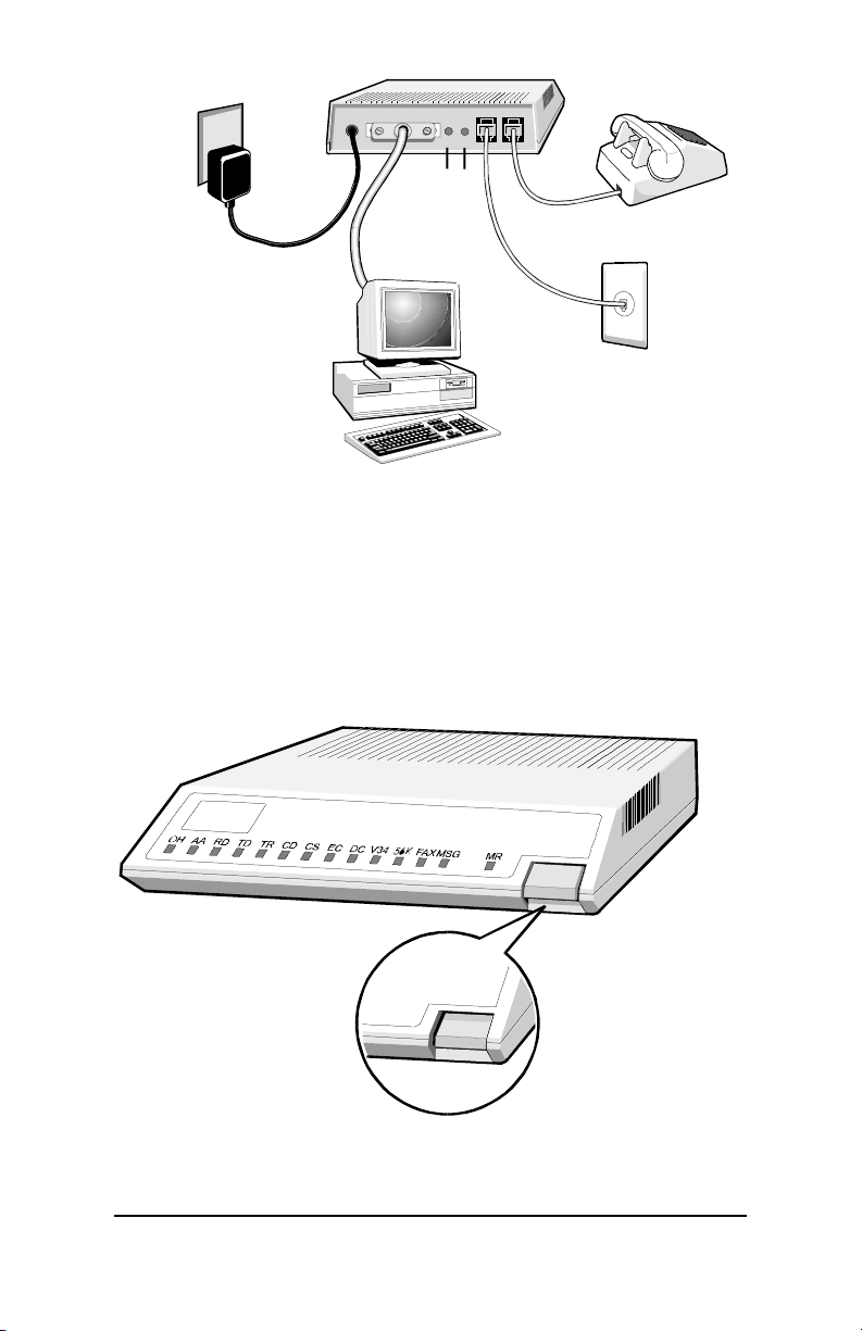
POWER
CONNECTION
MIC
SPK
Not available
on all models
TELEPHONE
(OPTIONAL)
COMPUTER
TELEPHONE LINE
Turn the computer back on.
7
Turn the faxmodem on by pushing in the power
8
button on the front, as shown in the following diagram.
The modem performs a brief self-test.
Chapter 1 Installing the Faxmodem 9
Page 10

After the self-test, the front panel status lights or LEDs
show the faxmodem’s current state. The MR light should
be on, which shows the faxmodem is ready for use.
Now you can install your fax and data communications
software. Follow the instructions provided with the software.
Summary of the Indicator Lights
Light Description
OH (Off Hook) Lights when the faxmodem is off hook.
AA (Auto-Answer)* Lights when Auto-Answer is activated. Blinks on
and off when detecting incoming ring.
RI (Ring Indicate)* Blinks on and off when detecting incoming ring.
AA (Auto-Answer) Blinks on or off when detecting incoming ring.
Lights if software uses the modem’s S register
0 to control auto-answer and sets S0 to 1-255
rings.
RD (Receive Data) Light flashes when data is sent from the faxmo-
dem to your computer or other serial device. At
high speeds light may appear on.
TD (Transmit Data) Flashes whenever data or commands are
transmitted from the serial port of your computer or other device to the faxmodem.
TR (Terminal Ready) Lights when the terminal is ready to send or
receive data.
CD (Carrier Detect) Lights when the Data Carrier Detect (DCD) sig-
nal from the faxmodem to the computer is on.
CS (Clear to Send) Lights when the faxmodem can accept data
from the computer. The light turns off when
the faxmodem is set for flow control (AT command &K3) and the faxmodem’s data buffer is
full, preventing data flow from the computer.
EC
(Error Correction)
DC
(Data Compression)
Lights when sending data using V.42 or MNP 4
error correction.
Lights when using V.42bis or MNP 5 data compression.
V.34 Lights when operating in V.34 mode.
10 Quick Start and Reference Guide
Page 11

56K* Lights when communicating in V.90 or
K56flex™ mode.
FAX Lights when fax connection has been made to a
remote faxmodem.
MSG Lights when faxes are waiting if your software
supports this feature.
MR (Modem Ready) Lights when the faxmodem is turned on.
Flashes when the faxmodem is in self-test
mode.
* Not available on all models
Chapter 1 Installing the Faxmodem 11
Page 12

Chapter 2 Using the Faxmodem
This chapter provides tips for setting up your communications software and using the modem. It also describes advanced telephony features.
See the software instructions included with your software for information about how to install and use the
programs included with this product.
After you set up your software, you are ready to start using your faxmodem. The best way to get familiar with your
software is to learn by doing.
• Try dialing a bulletin board or online service, or try
calling a friend with a modem and transferring a file.
• Send a fax and have someone send one back to you.
Using Other Voice, Fax, and Data Communications Software
If you have any difficulties installing or setting up other
communications software, it may be helpful to read Tips
for Selecting Setup Options on the next page.
Software programs are designed as a simple, user-friendly
interface that makes it easy to use the many features your
faxmodem offers. The software must first identify the modem and its special capabilities. Many software programs
identify the product automatically and configure themselves for the correct operating settings.
Installing most software takes you through a series of
setup options. With virtually all commercially available
software, selecting the correct description of the product
during installation means that you can accept all of the
default settings that the software suggests.
Using Initialization Strings
An initialization string is a group of AT command settings
that are sent to the faxmodem as soon as you start up the
software. The software determines which commands go
12 Quick Start and Reference Guide
Page 13

into the initialization string based on the device you select
during installation. The commands remain in effect
throughout the communications session, unless the software sends other commands to override them.
The software uses other AT command strings for other
purposes. For example, when you make a telephone call,
the software inserts AT commands in a dial string before
the telephone number you are calling. You can typically
use the AT command strings which are provided with the
software.
It is sometimes necessary to add other AT commands to
the strings as suggested in the next section, Tips for Se-
lecting Setup Options, and in Chapter 3. For a table of
AT commands, go to the Web site at www.modems.com.
Tips for Selecting Setup Options
In setting up some older software programs, you may be
asked to enter certain information. Most programs have
default settings that are correct for use with this modem,
and there is no need to change them. You should be aware
of the following items:
• If you are asked to select the “modem type” from a
menu and you do not see this modem listed by name
on the menu, select the most descriptive name, or
keywords, such as Hayes-compatible V.34 modem
(with or without a specific speed) or the generic Class
1 Modem. The more generic the type you choose, the
less likely that the software lets you use some of the
modem’s advanced features. It still performs basic
communications and fax functions.
• • In the dialing directory, all entries should be set to
115,200 bps (115.2K baud). All communications be-
tween the computer and the modem take place at
115,200 bps, independent of the modem-to-modem
speed. The modem auto-negotiates the highest speed
connection between itself and the other modem.
• If there is a section of your software called “Terminal
Settings,” make sure that Hardware Flow Control
(RTS/CTS) is ON (or YES). This is necessary in order
for V.42bis file transfers to work.
Chapter 2 Using the Faxmodem 13
Page 14

• • Set auto baud detect to OFF (or NO).
• Some programs ask “Send init if CD high?”, which
you should set to YES. Otherwise the modem may not
receive the proper initialization string.
• If your software suggests an initialization string for
this modem, you should use it. If this modem is not
listed by your software and no initialization string is
suggested, use the following initialization string:
AT &F
Note: If you are familiar with AT commands and you
save any settings in the modem’s nonvolatile
memory using the modem’s &W command, remove the &F from the initialization string. Otherwise the contents of the initialization string
overrides the saved settings.
• • If the software does not provide a dial string, use
ATDT if your telephone line uses tone dialing (as most
do), or ATDP if the line uses pulse dialing.
• • If your telephone service includes Call Waiting that
you can temporarily suspend by pressing *70, include
ATDT*70, in the dial string. (Note: Be sure to type the
comma). For pulse dialing, use ATDT1170 at the beginning of the dial string. For more information about
handling Call Waiting, contact your telephone company.
• If your fax software gives you the option of selecting
Class 1 or Class 2 fax drivers, select Class 2 if your
modem supports it. Class 2 may provide slightly faster
faxing. Otherwise select Class 1.
Using AT Commands
While using your software and modem you rarely, if ever,
need to send AT commands directly to the modem. If you
need to enter AT commands, you must do so from the
software’s terminal mode.
14 Quick Start and Reference Guide
Page 15

Using AT commands in terminal mode
1. Start your data communications program.
2. Change to terminal mode (also called command, local,
direct, or dumb mode).
3. Type in the AT command you need and press Enter.
When you finish, you can return to the data communications program’s standard user interface. See the program’s
documentation if you need help.
Returning to the Factory Settings
To return to the factory default settings for the modem:
In terminal mode, type AT &F and press Enter.
See the Web site at www.modems.com.
Chapter 2 Using the Faxmodem 15
Page 16

Chapter 3 Solving Common Problems
If your modem is not working, please read this chapter
and the communications software documentation carefully.
For installation problems, see Chapter 1 Installation.
This chapter covers four categories: General trouble-
shooting, echo troubleshooting, dial troubleshooting, and
connection troubleshooting.
For help with this problem… See
page…
The software cannot find the modem and the modem does not respond to AT commands.
17
The modem takes too long to hang up at the end of
a telephone call.
The modem fails to execute an AT command line. 19
No response appears after executing a command. 18
You receive an ERROR response. 18
The modem goes off-hook and seizes the telephone
line.
The modem does not auto-answer. 19
You encounter other communications problems. 19
You are uncertain about the DTR and DCD settings
referred to in your software manual.
The modem speaker volume is too high or too low. 20
Each character you type appears twice or no characters appear at all during data mode.
The modem does not automatically dial a call when
you send a Dial command line.
The modem can connect to some modems, but not to
others.
17
18
19
20
21
21
Continued on the next page…
16 Quick Start and Reference Guide
Page 17

For help with this problem… See
page…
The modem disconnects while communicating
with a remote system.
The modem does not make a data connection. 25
24
You receive bursts of errors occasionally, but
otherwise data quality is good.
Random errors occur in transmitted data. 25
Data is missing. 25
The quality of the voice messages needs to be
improved.
Your faxmodem is not communicating data as
fast as you expect.
25
26
26
General Troubleshooting
Problem: The software cannot find the modem and the
modem does not respond to AT commands.
(The following comments apply to many
other problems as well.)
Solution: The most common error with modems is that
the communications software is not configured
for the same serial port as the modem. Check
which serial port the modem is using. Make
sure that the software’s serial port setting
matches the modem’s serial port setting.
Problem: The modem takes too long to hang up at the
end of a telephone call.
Solution: Your modem may not be receiving the required
initialization string, which should include the
&C1 setting, from your software.
In your software, make sure you have selected
your modem. If not, select it and exit and restart
your communications software. If you still have
problems, add &C1 to the initialization string,
then exit and restart the software. (See Tips for
Selecting Setup Options in Chapter 2.)
Chapter 3 Solving Common Problems 17
Page 18

Problem: You type an AT command line and press En-
ter, but your modem fails to execute the
command line.
Solution: Be sure you type AT at the beginning of the
command line.
Make sure the communications software is
configured for the same serial port as your modem.
Be sure your modem is in terminal mode and
not in data mode when you type the command.
Problem: No response appears after executing a com-
mand.
Solution: If you typed a command but did not receive an
OK response from your modem:
Make sure the communications software and
modem are configured for the same serial port.
The E0 and Q1 commands may be in effect,
disabling echo and responses. Verify this with
the &V command. To enable echo and responses, type AT E1 Q0 and press Enter.
Be sure your modem is in terminal mode and
not in data mode when you type the command.
Problem: You receive an ERROR response when trying
to execute a command.
Solution: Check whether you typed the command cor-
rectly.
Check whether the command is a valid one.
Be sure your command line contains fewer
than 40 characters.
Problem: Your modem goes off-hook and seizes the
telephone line when there is an incoming
voice call that you want to take on your
telephone.
Solution: The modem is configured for auto-answer. Turn
off auto-answer in your software.
18 Quick Start and Reference Guide
Page 19

Problem: Modem does not auto-answer.
Solution: Your modem may not be configured to auto-
matically answer incoming calls. If you want
your fax or data software to answer calls, be
sure you have selected this option in your software.
Problem: You encounter other communications prob-
lems with your modem.
Solution: Check that your communications software has
been set up properly. Recheck the initialization
string and dial string specified in your software
manual. Remember that commands in the initialization string are sent to the modem each
time you start your software and override the
settings stored in the modem’s nonvolatile
memory.
Problem: You are uncertain about the Data Terminal
Ready (DTR) and Data Carrier Detect (DCD)
settings referred to in your software manual.
Solution: If your software requires that your faxmodem
ignore DTR (which is the faxmodem’s default
setting) and you are using the &D2 command
in the faxmodem’s initialization string or have
stored it in nonvolatile memory, your faxmodem
does not work properly. If this is the case, store
the &D0 command in nonvolatile memory.
Type: AT &D0 &W &Y0 and press Enter.
Make sure that your faxmodem initialization
string does not contain &D2.
If your software requires that your faxmodem
follow DTR, the previous considerations apply
in reverse. If you are having problems, include
&D2 in the faxmodem initialization string.
If your software requires that DCD always be
forced ON (which is the faxmodem’s default
setting), and you are using the &C1 command
in the faxmodem initialization string or have
stored it in nonvolatile memory, your faxmodem
does not work properly. If this is the case, store
the &C0 command in nonvolatile memory.
Chapter 3 Solving Common Problems 19
Page 20

Type: AT &C0 &W &Y0 and press Enter.
Also make sure that the faxmodem initializa-
tion string does not include &C1.
If your software requires that Data Carrier De-
tect follow carrier, the above considerations
apply in reverse. If you are having problems,
include &C1 in the faxmodem initialization
string.
Problem: The modem speaker volume is too low or too
high.
Solution: If the software allows you to control the
speaker, make sure the speaker is enabled and
set to a comfortable volume.
If the software does not have speaker settings,
add one of the following AT commands to the
initialization string:
L1 for low volume
L2 for medium volume
L3 for highest volume
M0 to turn the speaker off entirely
For example, if you want the volume low and
the software uses the initialization string
AT&F, change it to AT&FL1.
Echo Troubleshooting
Problem: Each character you type either appears
twice or no characters appear at all during
data mode.
Solution: Make sure that your software is in full-duplex
mode when you make a telephone call. If the
remote modem is not also in full-duplex mode,
change to terminal mode, type AT E0, and
press Enter. Then turn on your communications software’s local echo. Your software now
echoes commands during terminal mode and
any typing performed during data mode.
20 Quick Start and Reference Guide
Page 21

Dial Troubleshooting
Problem: The modem does not automatically dial a
call when you send a Dial command.
Solution: Make sure the modem speaker is turned on in
your software so that you can hear dialing
sounds. Also make sure that the telephone line
is plugged in.
Make sure that your are dialing a valid telephone number, including any required dial
prefixes.
If you are using tone dialing on a line that requires pulse dialing, the line may not be able to
accept tone-dialed calls. Select Pulse dialing in
your software or include the P command in
place of T in your Dial command line to specify
pulse dialing.
Make sure software dialing prefix is either
ATDT (for tone dialing) or ATDP (for pulse dialing).
Make sure your communications software and
modem are configured for the same serial port.
Make sure your modem has hung up from the
previous call. Select Hang Up in your software.
Or you can change to terminal mode, wait one
second, type ATH, and press Enter to hang up
the modem.
Connection Troubleshooting
Problem: The modem can connect to some modems,
but not to others.
Solution: If a remote modem does not respond because of
the extended negotiation process, you may have
to disable part or all of the negotiation process.
In the following table, “protocol” means error
correction and data compression.
Chapter 3 Solving Common Problems 21
Page 22

Note 1: The first two lines in the table are likely to be
the most valuable.
Note 2: In the command strings shown in the table that
follows, the character after “N” is zero, not the
letter “O.”
Note 3: Some commands vary because of the processor
used in the faxmodem. The use of Lucent- or
Rockwell-based processors is indicated on the
faxmodem box. You can also find out the processor type in a terminal emulator program by
typing ATI3 and pressing Enter. If the resulting response contains 207, the processor is Lucent-based; if the response contains 201, the
processor is Rockwell-based.
To force the different communication speeds
(speeds are maximums; actual speed depends
on line conditions and other factors)
Negotiate speed and protocol
(default setting)
Negotiate speed only, do not use protocol
To force protocol
Dualmode (V.90 or K56flex)—56000 bps
K56flex only (disable V.90)—56000 bps
V.90 only (disable K56flex)—56000 bps
Disable V.90 and autorate on V.34—33600 bps
V.34—33600 bps
V.32bis—14400 bps
V.32—9600 bps
2400 bps
1200 bps
Type these commands and
press Enter
AT &F
AT \N0
AT \N3
Lucent Rockwell
AT S109=1
(default)
AT S109=0 AT +MS=56,0
AT S109=2 AT +MS=12,0
AT S38=0
AT S37=19 AT +MS=11
AT S37=11 AT +MS=10
AT S37=9 AT +MS=9
AT S37=6 AT +MS=2
AT S37=2 AT +MS=1
(default)
22 Quick Start and Reference Guide
Page 23

Note 4: You may find it necessary or helpful to include
W2 in your initialization string or dialing prefix.
This enables responses that include the modem-to-modem speed.
Note 5: Some software allows these commands to be
added to the list of dial prefixes or the initialization string.
Note 6: When the protocol is forced, the modem will not
attempt to connect at other protocols if it cannot connect at the forced protocol. It will try to
connect at the fastest speed available within
the forced protocol.
There are other configurations that can be
forced as well. If you need to select a particular
configuration, use the AT command strings
shown next.
You can always return to the modem’s default
configuration by typing AT &F and pressing the
Enter key. If you do, the modem does not receive the commands in your software’s initialization string, as it normally would. Using the
ATZ command overcomes this problem if you
have saved all of your setup parameters in
nonvolatile memory. (To save setup parameters
in nonvolatile memory in AT terminal mode:
Type AT, followed by the parameter settings
you choose, followed by &W, and press Enter.
For example, if you type AT &C1 &D2 &W and
press Enter, the &C1 and &D2 parameter settings are stored in Profile 0.)
To force... Type these commands and press
Enter
Lucent Rockwell
MNP5/MNP4 operation
MNP4 only
LAPM only
Chapter 3 Solving Common Problems 23
AT \N2 AT \N5
AT \N2 %C0 AT \N5 %C0
AT \N4
Continued on next page
Page 24

“Normal” operation (The faxmodem communicates without any error correction or data
compression, but retains speed buffering
and auto-speed negotiation. It should not be
confused with the “standard” configuration.)
Auto-answer
AT \N0
AT S0=1
Problem: Your online service reports a connect speed
that doesn’t match your modem’s speed.
Solution: To get your online service software to report the
actual connect speed, add W2 to the end of the
initialization string, or to the dial prefix, just
before the D, as in these examples:
Initialization string: AT&F&C1&D2W2
Dial prefix: ATW2D
Consult your online service’s documentation for
details on initialization strings and dial prefixes. Actual connect speeds depend on your
modem’s speed, the equipment you’re connecting to, and phone line conditions.
Problem: Your modem disconnects while communicat-
ing with a remote system.
Solution: The remote system has hung up.
The telephone line disrupted your call. If your
telephone service includes Call Waiting, turn it
off if possible before making modem calls. Ask
your telephone company if you can temporarily
disable Call Waiting by pressing *70 (tone dialing) or dialing 1170 (pulse dialing). If so, include *70, (the comma is part of the code) for
tone dialing or 1170, for pulse dialing as a prefix with the telephone numbers in the software’s dialing directory. Or you can add the
code to the dial string or initialization string in
the software’s setup. Be sure to include the
comma. Note: This helps with outgoing but not
incoming calls.
24 Quick Start and Reference Guide
Page 25

Problem: Your modem does not make a connection.
Solution: If your modem places telephone calls but never
makes a connection, make sure you are dialing
the right number.
The remote modem may be turned off.
Problem: You receive bursts of errors occasionally, but
otherwise data quality is good.
Solution: The connection may have been established on
poor-quality or noisy telephone lines. Hang up
and place the call again to try to obtain a better
connection.
Someone may be picking up an extension connected to the line that your modem is using. If
the modem is sharing a telephone line with
other telephones, inform the other users when
you will be making a data call.
Your telephone line may have a Call Waiting
feature and a call is being received. See the
previous Call Waiting discussion.
Problem: Random errors occur or data is missing in
transmitted data.
Solution: Use the MNP or V.42 protocol if the remote mo-
dem supports one of these protocols. See the
table on page 23 for more information.
Select a lower baud rate in your communications software and place the telephone call
again.
If both modems are using the MNP or V.42
protocol, the only way this can occur is if your
modem and communications software are not
using the appropriate flow control. Configure
your communications software for RTS/CTS
(hardware) flow control. Your computer now
pauses for the transmission to be stored.
Chapter 3 Solving Common Problems 25
Page 26

Problem: Your faxmodem is not communicating data
as fast as you expect.
Solution: For data communication above 14,400 bps,
make sure that the modem at the other end of
the telephone connection also supports V.34.
Follow the recommendation provided under
Tips for Selecting Setup Options in Chapter 2
for setting the port speed in the software. Your
faxmodem’s speed may be affected by the speed
of your computer hardware and operating system.
If you are sending or receiving pre-compressed
data files such as BIN or HQX files, turn off the
faxmodem’s automatic data compression
feature before you call the remote modem.
Automatic data compression cannot compress
the files any further and may slow down their
transmission.
26 Quick Start and Reference Guide
Page 27

Appendix A: Product Summary
This modem hardware supports the following standards,
functions, and features:
Data Speeds:
• 56,000/33,600/31,200/28,800/26,400/24,000/
21,600/19,200/16,800/14,400/12,000/9600/7200/
4800/2400/1200/300 bps
• Data throughput up to 230,400 bps
Data Standards:
• V.90, K56flex, V.34, V.32bis, V.32, V.22bis, Bell 212A,
Bell 103, V.21, V.22A/B, and V.23 protocols
• V.42 LAPM and MNP
• V.42bis and MNP 5 data compression
Fax Speeds:
• 14,400/12,000/9600/7200/4800/2400/1200/300
send/receive fax
Fax Standards:
• V.33, V.29, V.17, V.27ter, and V.21 channel 2
• Class 1, Class 2 (some models), Group 3 fax
Approvals:
• FCC Part 15B and Part 68 Telecommunications approval; Industry Canada Emissions and Telecommunications approval; CE approval.
®
2-4 error correction
Features:
• Auto-negotiation of highest mutually supported level of
error correction, data compression, and modem speed.
• Auto fallback/fall forward on initial connection and
during call.
• Compatible with Hayes AT commands and S registers
• Line quality monitoring and auto-retrain.
• Flow control and speed buffering.
• Automatic terminal-to-modem speed sensing to
230,400 bps.
• Auto-dial/auto-answer.
• Tone, pulse, and adaptive dialing.
• Automatic self diagnostics.
Appendix A: Product Summary 27
Page 28

• Digital and analog loop-back diagnostics.
• Automatic adaptive equalization.
• Nonvolatile RAM for storage of up to four 35-digit tele-
phone numbers and alternate configurations
• Automatic gain control.
• Inactivity timer (when set, hangs up if no data in pro-
grammable time from 1 to 42 minutes).
• Call progress tone decoding – busy, ring, dial tone.
• Calling tone detection for both fax and data.
• Caller ID support (on some models)
• DTMF decoding for automatic detection of incoming
voice, fax, or data.
• Dual RJ-11 telephone jacks – one for telephone line, one for
optional telephone.
• Telephone cable with RJ-11 connectors.
28 Quick Start and Reference Guide
Page 29

Appendix B: Product Specifications
External
Configuration
Jacks
Size
Electrical Specifications
External faxmodem
(2) RJ-11 telephone
V.24/DB-25 female
Speaker (certain mod-
els only)
Microphone (certain
models only)
Power input
5.25" x 6.50" x 1.40"
Typical Power Requirements
Power Cube Provides
Fuse
Performance Specifications
Transmit Signal Level (Nominal)
Transmit Frequency Tolerance
Receive Signal Level
Receive Frequency Tolerance
105 to 130 VAC, 60 Hz
9 VDC, 600 mA
UL and CSA Approved
2A fuse (not user re-
placeable)
-10 ± 1 dBm
± 0.01 percent
-9 dBm to -43 dBm
±7 Hz
Appendix B: Product Specifications 29
Page 30

Appendix C: Regulatory Information
FCC Part 68 Telecommunications Statement
The Federal Communications Commission (FCC) has established Rules
which permit this device to be directly connected to the telephone network. This device is registered with the Federal Communications Commission (FCC) for direct connection to the telephone line using a standardized RJ11C telephone jack. This device complies with the Part 15,
Subpart B, and Part 68 requirements of the FCC rules.
The telephone company may make changes in its technical operations
and procedures; if such changes affect the compatibility or use of the
device, the telephone company is required to give adequate notice of the
changes.
If the telephone company requests information on what equipment is
connected to the line, inform them of:
1. The telephone number that this unit is connected to,
2. The ringer equivalence number,
3. The USOC jack required [RJ-11C], and
4. The FCC Registration Number.
Items (2) and (4) are indicated on the label attached to the underside of
the faxmodem. The ringer equivalence number is used to determine how
many devices can be connected to your telephone line. In most cases,
the sum of the RENs of all devices on any one line should not exceed five
(5.0). If too many devices are attached, they may not ring properly.
If this device should malfunction, it may also cause harm to the telephone network. Should this occur, this device should be disconnected
from the network until the source of the problem can be determined and
repair has been made. If a device which harms the network is not removed, the telephone company may temporarily disconnect service.
In the event of equipment malfunction, all repairs should be performed
at an authorized repair facility. It is the responsibility of users requiring
service to report the need for service to such a facility. Service facilities
are listed on the product’s warranty flyer.
The Telephone Consumer Protection Act of 1991 makes it unlawful for
any person to use a computer or other electronic device to send any
message via telephone fax machine unless such message clearly contains in a margin at the top or bottom of each transmitted page, or on
the first page of the transmission, the date and time sent, the identification of the business, entity, or individual sending the message, and the
telephone number of the sending machine. In order to program this information into your fax machine, refer to your faxmodem software
documentation for information on enabling fax branding.
30 Quick Start and Reference Guide
Page 31

Industry Canada Attachment
The Industry Canada label identifies certified equipment. This certification means that the equipment meets certain telecommunications network protective, operational, and safety requirements. The department
does not guarantee the equipment will operate to the user’s satisfaction.
Before installing this equipment, users should ensure that it is permissible to
be connected to the facilities of the local telephone company. The equipment
must also be installed using an acceptable method of connection. In some
cases, the company’s inside wiring associated with a single line individual
service may be extended by means of a certified connector assembly
(telephone extension cord). The customer should be aware that compliance
with the above conditions may not prevent degradation of service in some
situations.
Repairs to certified equipment should be made by an authorized Canadian maintenance facility designated by the supplier. For locations of the
authorized service facilities, please see the product’s warranty card. Any
repairs or alterations made by the user to this equipment, or equipment
malfunctions, may give the telecommunications company cause to request the user to disconnect the equipment.
Users should ensure for their own protection that the electrical ground
connections of the power utility, telephone lines and internal metallic
pipe system, if present, are connected together. This precaution may be
particularly important in rural areas.
Caution: Users should not attempt to make such connections themselves, but should contact the appropriate electrical inspection authority, or electrician, as appropriate.
The Ringer Equivalence Number (REN) assigned to each terminal device
helps to prevent overloading. You can use any combination of devices
subject only to the requirement that the sum of the RENs of all devices
on any one line should not exceed 5 (5.0). If too many devices are attached, they may not ring properly.
The Ringer Equivalence Number for your modem is indicated on the
label attached to the underside of the faxmodem.
Canadian Emissions Statement
This Class B digital apparatus meets all requirements of the Canadian
Interference-Causing Equipment Regulations.
Cet appareil numérique de la classe B respecte toutes les exigences du
Règlement sur le matériel brouilleur du Canada.
Appendix A: Regulatory Information 31
Page 32

Important Information
In the event you need to contact technical support or customer service,
you must provide the information below.
We recommend that you take a few moments to fill in the following information for your future reference.
Faxmodem Model _______________________
(located on the box)
Serial Number _______________________
(located on the bottom of an external modem
under the barcode)
Date of Purchase _______________________
Store or Dealer _______________________
2658-B 27032 ©1998
 Loading...