

Page 1

Operation Manual
USAGE AND SAFETY PRECAUTIONS . . . . . . . . . . . . . . . . . . . . . . . . . . . . . 2
Introduction . . . . . . . . . . . . . . . . . . . . . . . . . . . . . . . . . . . . . . . . . . . . . . . . . . 3
Controls and Functions . . . . . . . . . . . . . . . . . . . . . . . . . . . . . . . . . . . . . . . . . 4
Getting Ready to Play . . . . . . . . . . . . . . . . . . . . . . . . . . . . . . . . . . . . . . . . . . 6
Inserting the batteries . . . . . . . . . . . . . . . . . . . . . . . . . . . . . . . . . . . . . . . . . . . . . . . . . .6
Getting connected . . . . . . . . . . . . . . . . . . . . . . . . . . . . . . . . . . . . . . . . . . . . . . . . . . . .6
Quick Guide . . . . . . . . . . . . . . . . . . . . . . . . . . . . . . . . . . . . . . . . . . . . . . . . . . 8
Playing Patches (Play Mode) . . . . . . . . . . . . . . . . . . . . . . . . . . . . . . . . . . . 10
Panel display in play mode . . . . . . . . . . . . . . . . . . . . . . . . . . . . . . . . . . . . . . . . . . . . .10
Selecting a patch . . . . . . . . . . . . . . . . . . . . . . . . . . . . . . . . . . . . . . . . . . . . . . . . . . . .10
Using the internal tuner (bypass/mute function) . . . . . . . . . . . . . . . . . . . . . . . . . . . . .11
Adjusting the sound of a patch . . . . . . . . . . . . . . . . . . . . . . . . . . . . . . . . . . . . . . . . . .12
Using the Rhythm Function . . . . . . . . . . . . . . . . . . . . . . . . . . . . . . . . . . . . . 14
Turning Effects On and Off With Your Feet (Manual Mode) . . . . . . . . . . . 16
Changing the Sound of a Patch (Edit Mode) . . . . . . . . . . . . . . . . . . . . . . . 17
Patch configuration . . . . . . . . . . . . . . . . . . . . . . . . . . . . . . . . . . . . . . . . . . . . . . . . . . .17
Basic edit mode steps . . . . . . . . . . . . . . . . . . . . . . . . . . . . . . . . . . . . . . . . . . . . . . . .17
Changing a patch name . . . . . . . . . . . . . . . . . . . . . . . . . . . . . . . . . . . . . . . . . . . . . . .18
Storing and Swapping Patches . . . . . . . . . . . . . . . . . . . . . . . . . . . . . . . . . . 19
Other Functions . . . . . . . . . . . . . . . . . . . . . . . . . . . . . . . . . . . . . . . . . . . . . . 20
Changing effects in real time . . . . . . . . . . . . . . . . . . . . . . . . . . . . . . . . . . . . . . . . . . . 20
Using the hold delay function . . . . . . . . . . . . . . . . . . . . . . . . . . . . . . . . . . . . . . . . . . .23
Using the sampler function . . . . . . . . . . . . . . . . . . . . . . . . . . . . . . . . . . . . . . . . . . . . .25
Calibrating the expression pedal . . . . . . . . . . . . . . . . . . . . . . . . . . . . . . . . . . . . . . . .26
Resetting the GFX-5 to the factory default condition . . . . . . . . . . . . . . . . . . . . . . . . .27
Effect Types and Parameters . . . . . . . . . . . . . . . . . . . . . . . . . . . . . . . . . . . 28
◆
BOOST module . . . . . . . . . . . . . . . . . . . . . . . . . . . . . . . . . . . . . . . . . . . . . . . . . 28
◆
ISO/COMP (Isolator/Compressor) module . . . . . . . . . . . . . . . . . . . . . . . . . . . . . 28
◆
DRIVE module . . . . . . . . . . . . . . . . . . . . . . . . . . . . . . . . . . . . . . . . . . . . . . . . . . . 29
◆
EQ (Equalizer) module . . . . . . . . . . . . . . . . . . . . . . . . . . . . . . . . . . . . . . . . . . . . 30
◆
ZNR (ZOOM Noise Reduction) module . . . . . . . . . . . . . . . . . . . . . . . . . . . . . . . 30
◆
CABINET module . . . . . . . . . . . . . . . . . . . . . . . . . . . . . . . . . . . . . . . . . . . . . . . . 30
◆
MOD (Modulation) module . . . . . . . . . . . . . . . . . . . . . . . . . . . . . . . . . . . . . . . . . 31
◆
REV (Delay/Reverb) module . . . . . . . . . . . . . . . . . . . . . . . . . . . . . . . . . . . . . . . . 33
◆
TOTAL module . . . . . . . . . . . . . . . . . . . . . . . . . . . . . . . . . . . . . . . . . . . . . . . . . . 34
Troubleshooting . . . . . . . . . . . . . . . . . . . . . . . . . . . . . . . . . . . . . . . . . . . . . . 35
Specifications . . . . . . . . . . . . . . . . . . . . . . . . . . . . . . . . . . . . . . . . . . . . . . . . 35
GFX-5 Patch List . . . . . . . . . . . . . . . . . . . . . . . . . . . . . . . . . . . . . . . . . . . . . . . . . . . . .36
© ZOOM Corporation
Reproduction of this manual, in whole or in part, by any means, is prohibited.
Page 2
W
W
USAGE AND SAFETY PRECAUTIONS
SAFETY PRECAUTIONS
In this manual, symbols are used to highlight warnings and
cautions for you to read so that accidents can be prevented.
The meanings of these symbols are as follows:
This symbol indicates explanations about
extremely dangerous matters. If users
arning
ignore this symbol and handle the device
the wrong way, serious injury or death could
result.
This symbol indicates explanations about
dangerous matters. If users ignore this
Caution
symbol and handle the device the wrong
way, bodily injury and damage to the
equipment could result.
Please observe the following safety tips and precautions to
ensure hazard-free use of the GFX-5.
Power requirements
Since power consumption of this unit is fairly high,
arning
we recommend the use of an AC adapter whenever
possible. When powering the unit from batteries, use
only alkaline types.
[AC adapter operation]
• Be sure to use only an AC adapter which supplies 9 V
DC, 300 mA and is equipped with a "center minus" plug
(Zoom AD-0006). The use of an adapter other than the
specified type may damage the unit and pose a safety
hazard.
• Connect the AC adapter only to an AC outlet that
supplies the rated voltage required by the adapter.
•When disconnecting the AC adapter from the AC outlet,
always grasp the adapter itself and do not pull at the
cable.
•When not using the unit for an extended period,
disconnect the AC adapter from the AC outlet.
[Battery operation]
• Use four conventional IEC R6 (size AA) batteries
(alkaline).
• The GFX-5 cannot be used for recharging.
Pay close attention to the labelling of the battery to make
sure you choose the correct type.
•When not using the unit for an extended period, remove
the batteries from the unit.
• If battery leakage has occurred, wipe the battery
compartment and the battery terminals carefully to
remove all remnants of battery fluid.
•While using the unit, the battery compartment cover
should be closed.
Environment
Avoid using your GFX-5 in environments where it
Caution
will be exposed to:
• Extreme temperature
• High humidity or moisture
• Excessive dust or sand
• Excessive vibration or shock
Handling
Since the GFX-5 is a precision electronic device,
Caution
avoid applying excessive force to the switches and
buttons. Also take care not to drop the unit, and do not
subject it to shock or excessive pressure.
Alterations
Never open the case of the GFX-5 or attempt to
Caution
modify the product in any way since this can result in
damage to the unit.
Connecting cables and input and output
jacks
Caution
You should always turn off the power to the GFX-5
and all other equipment before connecting or
disconnecting any cables. Also make sure to
disconnect all cables and the AC adapter before
moving the GFX-5.
Usage Precautions
• Electrical interference
For safety considerations, the GFX-5 has been designed to
provide maximum protection against the emission of
electromagnetic radiation from inside the device, and
protection from external interference. However, equipment
that is very susceptible to interference or that emits
powerful electromagnetic waves should not be placed near
the GFX-5, as the possibility of interference cannot be
ruled out entirely.
With any type of digital control device, the GFX-5 included,
electromagnetic interference can cause malfunctioning and
can corrupt or destroy data. Care should be taken to
minimize the risk of damage.
• Cleaning
Use a soft, dry cloth to clean the GFX-5. If necessary,
slightly moisten the cloth. Do not use abrasive cleanser, wax,
or solvents (such as paint thinner or cleaning alcohol), since
these may dull the finish or damage the surface.
Please keep this manual in a convenient place for
future reference.
Introduction
Thank you for selecting the ZOOM GFX-5. This product is a sophisticated Guitar Effects Processor with the
following features.
●
Versatile array of effects
The Variable Architecture Modeling System
(VAMS) developed by ZOOM adapts the internal
configuration of the unit to achieve exactly the
desired sound. The GFX-5 provides 74 choices,
ranging from distortion and modulation effects to
booster functions and a cabinet simulator that
duplicates the sound of various guitar amps.
●
Full complement of distortion effects
33 distortion type effects not only recreate the
characteristics of famous vintage amps but also
duplicate the sound and operation of renowned
compact effects and pedals. The [TURBO] key lets
you boost the sound pressure in an instant, and the
[EDGE] key creates a bright treble edge. A wide
variety of drive sounds are only a keypress away.
●
120 ready-to-use patches
Effect module setting combinations can be stored as
patches. The GFX-5 offers 60 user patches which
can be freely modified, plus 60 preset patches.
Together, these 120 settings let you make great
music straight away.
Intuitive operation and key layout
●
The knobs and keys on the panel of the unit are
designed for maximum usability. Choose distortion
types or adjust equalizer settings in a flash. The
expression pedal is great for controlling effect
parameters in real time. The GFX-5 practically
comes alive during a performance.
Newly developed ARRM feature
●
ARRM (Auto-Repeat Real-time Modulation) is a
fascinating concept. Using built-in control
waveforms, it lets you rhythmically shape the signal
in many ways. Create totally novel sounds that will
captivate listeners. You can even use the expression
pedal to adjust the modulation depth of the ARRM
feature.
●
Integrated drum machine
60 built-in rhythm patterns using natural-sounding
PCM sources are available, which is great for
practice or a quick jam session. ARRM cycles can
be synchronized to the rhythm tempo, letting you
alter effects in sync with the flow of the music. The
creative possibilities are limitless.
●
6-second sampling feature
A guitar phrase or the signal from an input source
such as a CD player can be sampled for up to 6
seconds and stored in the internal memory. The
recorded sample can be played back at a slower
speed without altering the pitch. This is a great tool
for enhancing a live performance or for copying a
lick or fast-playing phrase.
●
Energize creates dynamic sound
The Energize is another innovation with immense
appeal. Simply by turning a knob, you can optimize
the sound characteristics to match the playback
system. Enjoy powerful, dynamic sound even with a
small guitar amp or an audio system with flat
response.
Designed for use on stage
●
The GFX-5 can be powered either from an AC
adapter or from batteries. With one set of alkaline
batteries, the unit will operate continuously for up
to 10 hours. A special mode lets you switch major
effects on or off with your foot or specify the
rhythm tempo during a performance. Operate the
unit like compact effects, while accessing a vast
array of functions.
2
ZOOM GFX-5
ZOOM GFX-5
3
Page 3
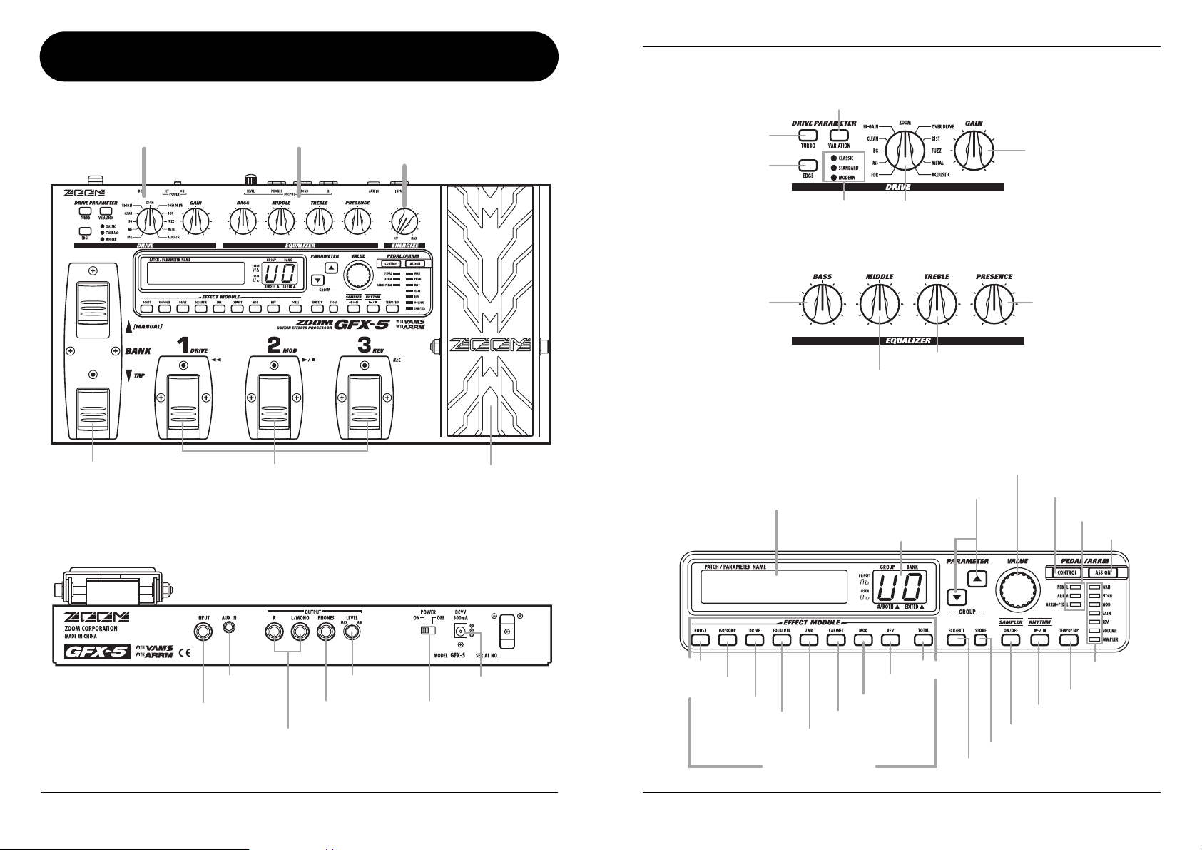
Controls and Functions
Controls and Functions
Drive section
Top Panel
Drive section Equalizer section
AMPDRV
BANK [Q]/[W] foot switches
Rear Panel
Foot switches [1] – [3]
Energize section
[ENERGIZE] knob
Expression pedal
[TURBO] key
[EDGE] key
[VARIATION] LED
Equalizer section
[BASS] knob
Display
[VARIATION] key
[DRIVE] knob
[MIDDLE] knob
PARAMETER [Q]/[W] keys
[GROUP/BANK] indicator
[GAIN] knob
[PRESENCE] knob
[TREBLE] knob
[VALUE] dial
[CONTROL] key
[CONTROL] LEDs
[ASSIGN] key
AMPDRV
[AUX IN] jack
[INPUT] jack
[OUTPUT L/MONO]/[OUTPUT R] jacks
[LEVEL] knob
[PHONES] jacks
[POWER] switch
4
[DC IN] jack
ZOOM GFX-5
[BOOST] key
[ISO/COMP] key
[DRIVE] key
[EQUALIZER] key
ZOOM GFX-5
[MOD] key
[CABINET] key
[ZNR] key
Effect Module keys
[TOTAL] key
[REV] key
[ASSIGN] LEDs
[TEMPO/TAP] key
[RHYTHM] key
[SAMPLER] key
[STORE] key
[EDIT/EXIT] key
5
Page 4
Getting Ready to Play
Getting Ready to Play
Inserting the batteries
To use the GFX-5 on battery power, insert batteries
as shown below.
1.
Turn the unit over and open the battery
compartment cover. (Push the tab to
unlock and then raise the cover.)
Battery compartment cover
OPEN
GFX-5 bottom
2.
Insert the batteries with correct (+) (-)
polarity into the battery compartment.
Battery
compartment
cover
3.
Close the battery compartment cover.
(Make sure that the tab is properly
engaged.)
Four IEC R6 (size AA)
batteries
Tab
Battery polarity
alternates
for each slot.
OTE
N
• When not using the unit for an extended
period, remove the batteries to prevent the
possibility of damage by leaking battery fluid.
• When the indication “BATT” appears on the
display, the batteries are almost exhausted.
Replace the batteries as soon as possible
with fresh ones.
BATT
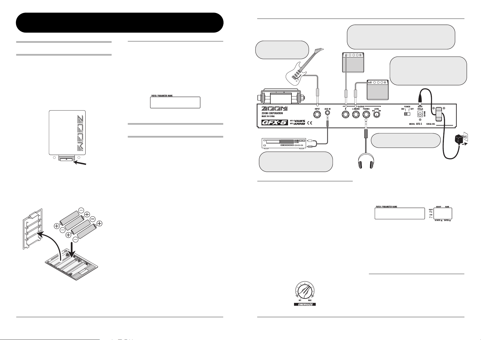
Getting connected
1.
Make sure that the amplifier and the
GFX-5 are switched off.
Turn the volume at the amplifier to minimum.
2.
To power the unit from the AC adapter,
insert the small plug of the adapter cable
into the [DC IN] jack on the GFX-5. Then
plug the adapter into an AC outlet.
3.
Connect the guitar to the [INPUT] jack of
the GFX-5, using a mono cable.
4.
Connect the [OUTPUT] jack of the GFX-5
to the guitar amp, using a mono cable.
5.
To monitor the sound with headphones,
plug the phones into the [PHONES] jack.
6.
Turn power on in the following order:
GFX-5
→
amplifier.
Connect the guitar output
jack to the [INPUT] jack
on the GFX-5.
Guitar
CD player or other source
To sample a signal from a CD or MD
player or similar, connect the player
output to the [AUX IN] jack.
N
OTE
If you turn the GFX-5 on while the amplifier is
already powered up, damage to the speaker may
result. Always turn power to the amplifier on last.
When turning off the system, proceed in the
opposite order.
7.
Raise the volume setting of the
instrument and amplifier, and adjust the
[LEVEL] knob on the rear panel of the
GFX-5.
8.
While playing your instrument, turn the
[ENERGIZER] knob until the sound quality
is as desired.
When using only one guitar amp, connect it to the
[OUTPUT L/MONO] jack. By connecting another guitar
amp to the [OUTPUT R] jack, you can achieve reverb
and chorus sound with a wide stereo spread.
Loop the cable of the AC adapter
around the hook before connecting it
to the [DC IN] jack. This will prevent
Guitar amps
Connect the separately available AC
adapter (ZOOM AD-0006) here.
Headphones
The [ENERGIZE] knob serves to match the unit to
the playback environment. As you turn the knob,
the display changes as follows.
ENERGY
Turning the knob clockwise emphasizes the low
range, and turning it counterclockwise emphasizes
the high range. The “oF” setting means that the
Energize function is turned off.
H
INT
9.
the plug from being disconnected if the
cable is accidentally pulled.
AC adapter
15
Energize setting
(oF, 1 - 30)
The Energize setting applies to the output sound
of all signals except those from the [AUX IN] jack.
To turn the system off, proceed in the
opposite order than when turning it on.
6
ZOOM GFX-5
ZOOM GFX-5
7
Page 5
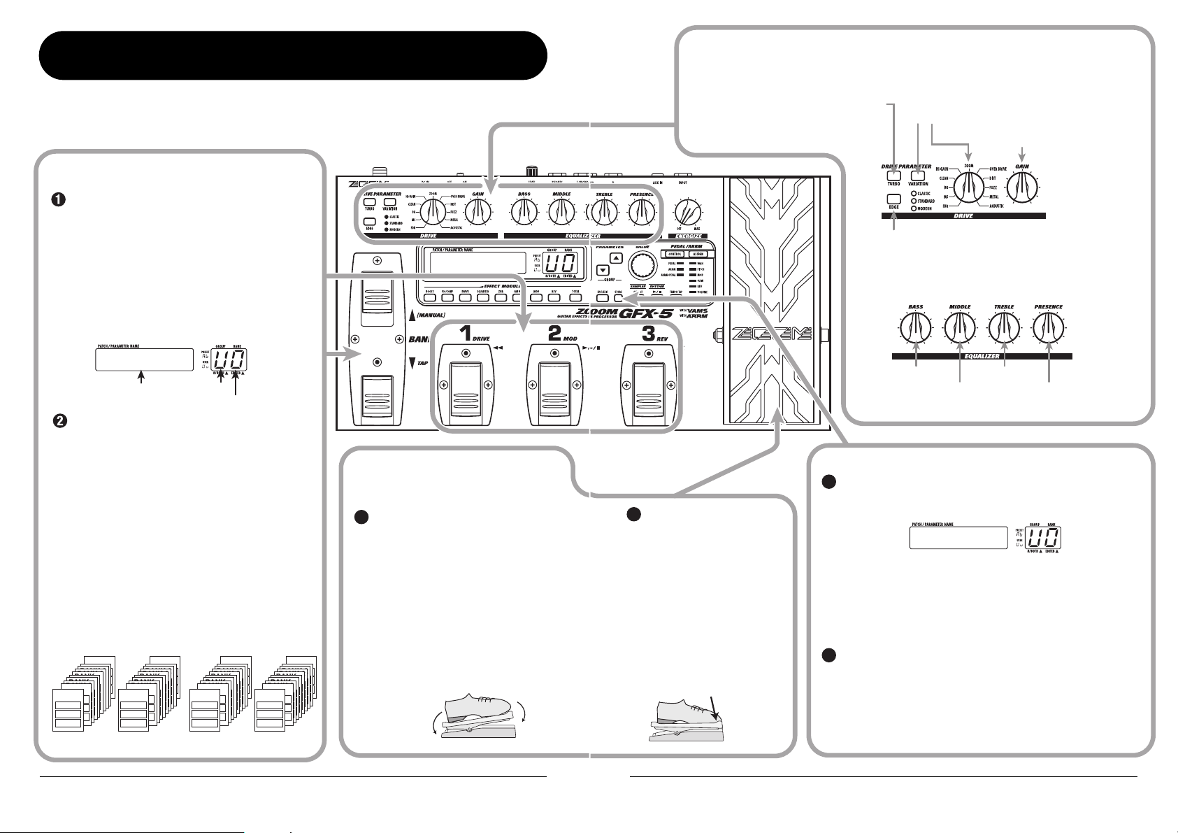
Quick Guide
When you turn on the GFX-5, it is in play mode. This section explains the basic steps in this mode, allowing you
to use the unit right away.
Selecting a patch
To select a patch, press one of the foot switches
[1] - [3] whose LED is not lit.
The single effects (effect modules) in the GFX-5 can
be combined, and parameter settings for each effect
can be changed to achieve a desired sound. Such a
combination of effects with certain parameter
settings is called a patch. Patches are always called
onto the panel in banks of three, and the foot
switches [1] - [3] are used to select the patch.
[Display in play mode]
AMPDRV
Patch name
To switch to a patch in another group or bank,
use the BANK [Q]/[W] foot switches and then
the foot switches [1] - [3].
Patches are organized in user groups (U, u) which
can be modified and preset groups (A, b) which are
read-only. Each group comprises ten banks
numbered from 0 to 9, and each bank has three
patches.
The BANK [Q]/[W] foot switches select groups
and banks in the order A0 – A9, b0 – b9, U0 – U9,
u0 – u9.
* You can also use the PARAMETER [Q]/[W] keys to
directly switch groups.
◆ For a detailed explanation of patch switching, see
page 10.
User groups Preset groups
BANK 9
BANK 2
BANK 2
BANK 2
BANK 2
BANK 2
BANK 2
BANK 2
BANK 1
BANK 0
PATCH 1
PATCH 1
PATCH 2
PATCH 2
PATCH 3
PATCH 3
Group U Group u Group A Group b
BANK 2
BANK 2
BANK 2
BANK 1
BANK 0
PATCH 1
PATCH 1
PATCH 2
PATCH 2
PATCH 3
PATCH 3
BANK 9
BANK 2
BANK 2
BANK 2
BANK 2
Group
BANK 2
BANK 2
BANK 2
BANK 1
BANK 0
PATCH 1
PATCH 1
PATCH 2
PATCH 2
PATCH 3
PATCH 3
Bank number
BANK 9
BANK 2
BANK 2
BANK 2
BANK 2
BANK 2
BANK 2
BANK 1
BANK 0
PATCH 1
PATCH 1
PATCH 2
PATCH 2
PATCH 3
PATCH 3
BANK 9
BANK 2
BANK 2
BANK 2
BANK 2
BANK 2
Altering an effect
with the pedal
Move the expression pedal up or down
1
while playing your instrument.
The effect depth or volume or another
parameter of the effect will change in real
time as you move the expression pedal.
(Which parameter changes depends on the
patch.)
* For some patches, the pedal has no effect.
◆ For an explanation of effect control with
Move back
and forth
AMPDRV
the pedal, see page 20.
Changing the sound of a patch in play mode
While playing your instrument, operate the following knobs and keys.
[Drive section]
Setting this key to ON will increase
To switch the effect module
2
on or off, push the
expression pedal fully down.
The expression pedal also
incorporates a push-down
switch that allows on/off
control of a specific effect
module.
◆ For an explanation of how to
select the module to be
operated with the pedal, see
page 20.
Push down
all the way
[TURBO] key
the sound pressure of the patch.
[Equalizer section ]
The knobs adjust boost/cut for each frequency range.
◆ For a detailed explanation of how to edit effects, see page 17.
Storing effects
Press the [STORE] key.
1
The GFX-5 goes into store standby mode.
If necessary, use the BANK [Q]/[W] foot switches and the foot
switches [1] - [3] to select the bank and patch number in which to
store the current effect settings.
* If a patch from a preset group was selected, the patch number 1 of
"U0" (user group) will be selected as the default store target.
To carry out the store process, press the [STORE] key once
2
more.
To cancel the operation, press the [EDIT/EXIT] key.
◆ For a detailed explanation of the store procedure, see page 19.
◆ For information on how to return the user group patches to the
factory default condition, see page 27
[VARIATION] key/[DRIVE] knob
Serve to select the distortion type.
[EDGE] key
Setting this key to ON will emphasize the high
frequency content of the patch.
[BASS] knob
[MIDDLE] knob
STORE?
[GAIN] knob
Adjusts the distortion depth.
[TREBLE] knob
[PRESENCE] knob
Quick Guide
8
ZOOM GFX-5
ZOOM GFX-5
9
Page 6
Playing Patches (Play Mode)
The condition where you call up patches stored in the memory of the GFX-5 and use them for playing your
instrument is called play mode. When you turn the GFX-5 on, it is initially always in this mode. The various
operations possible in play mode are described in this section.
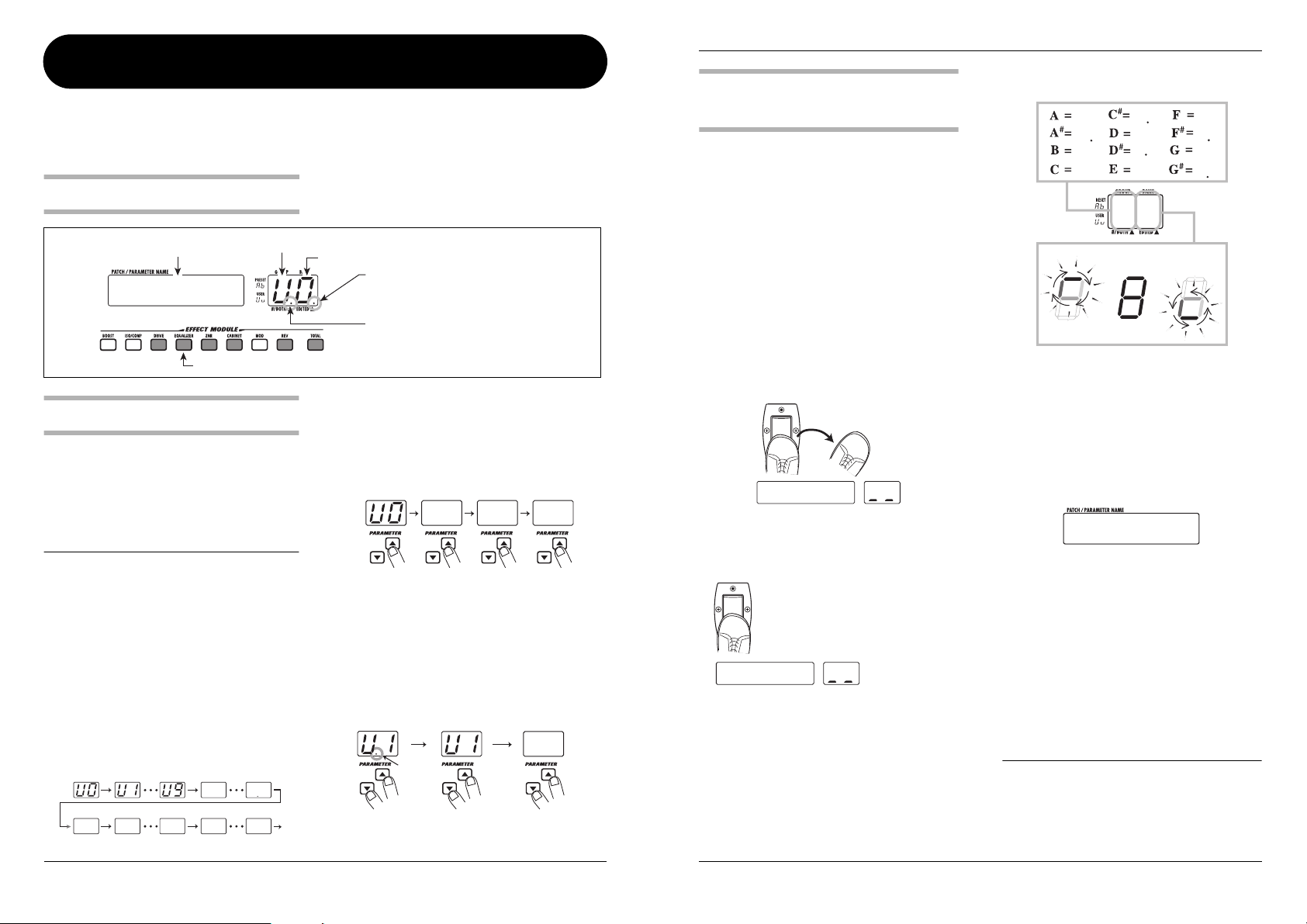
In play mode, the panel shows the following
Panel display in play mode
Patch name
Group (A/b/U/u)
AMPDRV
Keys for effect modules that are ON in the currently selected patch are lit.
Selecting a patch
1.
To select a patch in play mode, press one
of the foot switches [1] - [3] whose LED
is not lit.
The LED of the foot switch for the patch that is
currently selected is lit.
N
OTE
If you press the foot switch whose LED is lit, the
unit goes into bypass/mute mode ( → p. 11).
2.
To select a patch in another group or bank,
use the BANK [
then the foot switches [1] - [3] to select the
group and bank.
For example, if you repeatedly press the BANK
[Q ] foot switch, the group/bank is switched as
follows.
User groups
Preset groups
A0 A1 A9 B0 B9
Q
]/[
W
] foot switches and
U0 U9
information.
Bank number (0 - 9)
When a dot (.) is shown here, an effect
parameter has been changed.
When a dot (.) is shown here, patches can
be selected from a user group or preset
group.
3.
To directly switch groups, use the
PARAMETER [
Pressing the PARAMETER [Q ] key moves to the
next higher group and pressing the PARAMETER
[W ] key moves to the next lower group.
Q
]/[
W
] keys.
U0 A0 B0
4.
If you want to select only patches from a
user group or preset group, press both
PARAMETER[
Each time you press both PARAMETER [Q ]/[W]
keys together, the group type changes.
Both group
Q
] /[W] keys together.
User groups
only
Preset groups
only
A1
Dot is lit
Using the internal tuner
(bypass/mute function)
The GFX-5 has a built-in auto-chromatic tuner for
guitars. To use the tuner function, the built-in
effects must be bypassed (temporarily turned off) or
the unit must be muted (original sound and effect
sound turned off).
1.
To set the GFX-5 to the bypass (mute)
condition, press the foot switch of the
currently selected patch (the switch
whose LED is lit) in play mode.
Pressing and immediately releasing the foot switch
sets the GFX-5 to the bypass condition. The
expression pedal is automatically switched to
function as a volume pedal.
Bypass
Release immediately
BYPASS
Pressing and holding the foot switch for more than
one second sets the GFX-5 to the mute condition.
Mute
Press and release after more than 1 second
MUTE
2.
Play the open string you want to tune.
The [GROUP/BANK] indicator shows the note
which is closest to the current pitch. Adjust the
pitch so that the indicator shows the desired note.
Playing Patches (Play Mode)
The note is shown on the left part of the indicator.
A
A
B
C
C
D
D
E
F
F
G
G
A8
Pitch is sharp Correct pitch Pitch is flat
The more the pitch is off, the faster the rotation
of the indicator.
3.
To change the reference pitch of the
tuner, use the [VALUE] dial.
The current reference pitch is briefly shown on the
display. The default setting after power-on is center
A = 440 Hz.
440HZ
Reference pitch value
While the reference pitch is shown, you can change
the pitch by turning the [VALUE] dial.
The setting range is 435 - 445 Hz in 1-Hz steps.
When the GFX-5 is turned off and on again, it will
be reset to 440 Hz.
4.
To return to the play mode, press one of
the foot switches [1] - [3].
The patch of that foot switch becomes active again.
NOTE
If you switch the bank/group while using the
tuner, the tuner function will be temporarily
disabled. When you return to the original bank/
group, the tuner function becomes active again.
10
ZOOM GFX-5
ZOOM GFX-5
11
Page 7

Playing Patches (Play Mode)
Adjusting the sound of a
patch
After selecting a patch in play mode, you can use
the knobs and keys on the panel to adjust
parameters such as distortion type and depth,
equalizer settings, etc.
1.
In play mode, select the patch you want to
use.
2.
To change the distortion type, use the
[DRIVE] knob and [VARIATION] key in the
drive section.
The distortion type used for the DRIVE module can
be switched with the [DRIVE] knob and
[VARIATION] key. Turn the [DRIVE] knob to
select a general distortion category (amp or effect
pedal type), and use the [VARIATION] key to select
a variation within that category.
Each push of the [VARIATION] key cycles through
the CLASSIC → STANDARD → MODERN →
OFF (DRIVE module off) settings, and the
corresponding LED lights up. For details on
category and variation characteristics, see page 29.
(1) Select general distortion category
with [DRIVE] knob.
3.
To adjust the gain (distortion depth) of the
DRIVE module, turn the [GAIN] knob in
the drive section.
When you turn the knob, the current gain setting
appears on the [GROUP/BANK] indicator, and the
“EDITED” dot appears. When you return the gain
to the original setting, the dot disappears.
GAIN
When a dot is shown here,
an effect parameter was edited.
20
NOTE
If you turn the [GAIN] knob while a patch is
selected for which the DRIVE module is off, the
indication “-OFF-” appears on the display and
the knob has no effect.
-OFF-
4.
If necessary, use the [TURBO] key or
[EDGE] key to adjust the overall sound of
the patch.
The [TURBO] key and [EDGE] key let you touch
up the sound of each patch. The [TURBO] key
increases the overall sound pressure (intensity) of
the patch, and the [EDGE] key enhances the treble.
You can also set both keys to ON together.
Low range
Mid range
While you operate a knob, the display shows the
name of the current range, and the [GROUP/
BANK] indicator shows the current setting (-12 – 0
– 12).
BASS G
Very high range
High range
10
NOTE
If you turn a knob in the equalizer section while a
patch is selected for which the EQUALIZER
module is off (effect module [EQUALIZER] key
not lit), the indication “-OFF-” appears on the
display and the knob has no effect. Press the
[EQUALIZER] key to turn it on first.
6.
To switch an effect module on or off,
press the effect module key for that
module.
Playing Patches (Play Mode)
PATLVL
25
HINT
Any changes you have made in play mode will be
lost when you switch the patch. If necessary,
store the patch to retain the changes (→ p. 19).
Lit
Out
(2) Select variation in selected
category with [VARIATION] key.
(DRIVE module is off)
NOTE
If you turn the [DRIVE] knob or push the
[VARIATION] key while a patch is selected for
which the DRIVE module is off (effect module
[DRIVE] key not lit), the DRIVE module is
automatically turned on ([DRIVE] key lights up).
12
5.
To provide EQ adjustment, use the knobs
in the equalizer section.
The knobs in the equalizer provide boost or cut in
the following ranges.
ZOOM GFX-5
The light of the effect module key comes on or goes
out, and the module is toggled between on and off.
7.
To adjust the overall volume level of the
patch (patch level), turn the [VALUE] dial.
The patch level is a parameter that controls the
combined original sound and effect sound level. It
can be set in the range of 1 - 30. During adjustment,
the [GROUP/BANK] indicator shows the actual
setting.
ZOOM GFX-5
13
Page 8

Using the Rhythm Function
Using the Rhythm Function
The GFX-5 incorporates 60 rhythm patterns which can be selected for playback. This is convenient for practice
or a quick jam session.
1.
To activate the rhythm function, press the
[RHYTHM] key in play mode.
The key lights up and rhythm pattern playback
starts. The [TEMPO/TAP] key flashes in sync with
the current tempo.
8BEAT
Pattern name Pattern number
2.
To change the rhythm pattern, turn the
1
[VALUE] dial while the rhythm pattern
name is shown on the display.
3.
To change the tempo, press the [TEMPO/
TAP] key and then turn the [VALUE] dial.
When you press the [TEMPO/TAP] key, the current
tempo setting (BPM) appears on the display. While
this is shown, turning the [VALUE] dial will change
the tempo.
BPM120
Rhythm pattern tempo
If you tap the [TEMPO/TAP] key repeatedly, the
interval of the last two taps is automatically
detected and taken as the new tempo (tap tempo
setting function).
HINT
The tempo set in this way can be synchronized
to the control waveform cycle for the ARRM
function (→ p. 20). It can also be linked to the
DELAY TIME parameter of the REV module (→ p.
34).
4.
To change the volume of the rhythm
sound, press the PARAMETER [
Q
]/[W]
keys during rhythm pattern playback to
bring up the indication “LVL xx” (where xx
is a number) on the display, and then turn
the [VALUE] dial.
The rhythm pattern playback volume changes.
LVL 20
Rhythm pattern playback volume
HINT
By pressing one of the PARAMETER [Q]/[W]
keys repeatedly, you can cycle through the
rhythm pattern name, tempo, and playback
volume indication.
5.
To stop rhythm pattern playback, press
the [RHYTHM] key once more.
HINT
• When the GFX-5 is in manual mode (→ p. 16),
you can use the BANK [W] switch to bring up
the tempo indication on the display or to set
the tap tempo.
• If a rhythm pattern is played while editing a
patch, only the tempo can be changed.
Rhythm pattern list
Rhythm pattern Display Indicator
8 BEAT 1
8 BEAT 2
8 BEAT 3
8 BEAT 4
8 BEAT 5
8 BEAT SHUFFLE 1
8 BEAT SHUFFLE 2
16 BEAT 1
16 BEAT 2
16 BEAT 3
16 BEAT 4
16 BEAT SHUFFLE
3/4
6/8 ROCK
5/4
5/4 ROCK
ROCK'n ROLL 1
ROCK'n ROLL 2
ROCK 1
ROCK 2
1970s ROCK
HARD ROCK 1
HARD ROCK 2
HARD ROCK 3
METAL 1
METAL 2
THRASH
PUNK
POP 1
POP 2
8BEAT
8SHUFL
16BEAT
16SHFL
3/4
6/8
5/4
ROCK
70ROCK
HARD
METAL
THRASH
PUNK
POP
Rhythm pattern Display Indicator
1
2
3
4
5
1
2
1
2
3
4
1
2
1
2
1
2
1
2
3
1
2
1
DANCE 1
DANCE 2
DANCE 3
FUNK 1
FUNK 2
BALLAD 1
BALLAD 2
BLUES 1
BLUES 2
COUNTRY
BOSSA NOVA
JAZZ 1
JAZZ 2
REGGAE
SKA
LATIN 1
LATIN 2
SAMBA 1
SAMBA 2
AFRO
MOTOWN
EUROBEAT
FUSION
OLDIES
METRO (triple time)
METRO (quadruple time)
METRO (quintuple time)
METRO (sextuple time)
METRO (septuple time)
METRO
DANCE
FUNK
BALLAD
BLUES
CONTRY
BOSSA
JAZZ
REGGAE
SKA
LATIN
SAMBA
AFRO
MOTOWN
EURO
FUSION
OLDIES
METRO
METRO
1
2
3
1
2
1
2
1
2
1
2
1
2
1
2
3
4
5
6
7
2
14
Tap repeatedly
ZOOM GFX-5
ZOOM GFX-5
15
Page 9

Tur ning Effects On and Off With Your Feet
(Manual Mode)
Changing the Sound of a Patch
(Edit Mode)
Manual mode is a special mode in which you can use the foot switches to turn effect modules on and off or to
change the rhythm pattern tempo. This is useful for example if you want to turn only certain effect modules on
and off during a performance.
1.
To switch the GFX-5 to manual mode,
hold the BANK [
while the unit is in play mode.
The indication “MANUAL” appears on the display,
showing that the GFX-5 has switched to manual
mode.
Q
] switch depressed
3.
To change the tempo of the rhythm
pattern, tap the BANK [
repeatedly in the desired interval.
The interval of the last two taps is automatically
detected and taken as the new tempo.
W
] switch
BPM 95
MANUAL
Tap repeatedly
2.
To switch effect modules on and off, press
one of the foot switches [1] - [3].
When the GFX-5 is in manual mode, the modules
DRIVE, MOD, and REV can be turned on and off
with foot switches [1] - [3]. The modules are
assigned as follows.
Lit:
module is on
DRIVE module
MOD module
Out:
module is off
REV module
H
INT
By programming a patch beforehand to link the
ARRM control waveform (→ p. 20) or the DELAY
TIME parameter of the REV module (→ p. 34) to
the pattern tempo, you can control these
parameters manually during a performance.
4.
To return to play mode, press the BANK
[
Q
] switch once more.
The edit mode allows you to freely alter the parameters that make up a patch, so that you can create your own
patches. This section describes how to do this.
INPUT OUTPUT
patches from a preset group are read-only. When
Patch configuration
Each patch of the GFX-5 consists of several effects
(effect modules), as shown in the illustration above.
A patch is a stored combination of modules, each
with their distinct parameter settings.
Within each module, there are several different but
related effects which are called effect types. For
example, the MOD (modulation) module comprises
effect types such as CHORUS, PHASER, and
WAH, of which one can be selected.
The elements that determine the sound of a patch
are called effect parameters. Each module has
certain effect parameters, whose value can be
adjusted with the effect module keys,
PARAMETER [Q]/[W] keys, [VALUE] dial, etc.
NOTE
Also within the same module, different effect
types will have different parameters.
Basic edit mode steps
This section describes the basic procedure for
editing patches in edit mode. For information on
effect types and parameters in the various modules,
see the section “Effect Types and Parameters” on
pages 28 – 34.
1.
In play mode, select the patch you want to
edit.
Patches for editing can be selected from either a
user group (U/u) or a preset group (A, b). However,
you have altered such a patch and you want to store
it, you must select a user group patch as store target
(patch number 1 in the user group bank “U0” is
automatically preselected).
2.
To activate the edit mode, press the
[EDIT/EXIT] key.
The first time you switch to edit mode after the unit
was turned on, the parameter PATLVL (patch level)
of the TOTAL module will be selected.
PATLVL
3.
Press the effect module key for the
module that you want to edit.
The effect type currently selected for that module is
shown on the display.
20
Effect type
ROOM
HINT
If a module is selected that is currently off, the
key flashes more slowly.
4.
To toggle the on/off status of the selected
module, press the same key again while
the effect type is being shown.
The effect type display changes to “-OFF-”.
To return the effect module to “on” status, press the
key again.
16
ZOOM GFX-5
ZOOM GFX-5
17
Page 10

Changing the Sound of a Patch (Edit Mode)
-OFF-
5.
To change the effect type for the selected
module, turn the [VALUE] dial.
HALL
6.
To change a parameter value, press one
of the PARAMETER [
When you press the key, the parameters of the
currently selected effect type are called up on the
display one by one. The [GROUP/BANK] indicator
shows the parameter value.
TIME
When a dot is shown here, the patch was edited.
If you return the parameter to the original value,
the dot will disappear.
7.
Turn the [VALUE] dial to change the
parameter value.
For some modules such as DRIVE and
EQUALIZER, effect types and parameters can be
changed directly with the knobs and keys on the
panel.
8.
Repeat steps 3 - 7 to edit other modules.
9.
When editing is completed, press the
[EDIT/EXIT] key.
The unit returns to the play mode. If any element of
the patch has been changed, the “EDITED” dot is
shown on the [GROUP/BANK] indicator.
NOTE
If you wish to keep the patch, be sure to perform
the store operation (→ p. 19) . Otherwise all
changes will be permanently lost as soon as you
switch to another patch.
Q
]/[W] keys.
20
Changing a patch name
If you wish, you can assign a new name to an edited
patch. Proceed as follows.
1.
In edit mode, press the [TOTAL] key.
2.
Use the PARAMETER [Q]/[W] keys to
bring up the patch name on the display.
The flashing character is the one that can be
changed.
Character
to change
3.
Use the PARAMETER [Q]/[W] keys to
select the character, and turn the [VALUE]
dial to change the character.
Available characters are listed on page 34.
4.
Repeat step 3 until the name is as desired.
Then press the [EDIT/EXIT] key to return
to the play mode.
Do not forget to store the patch (→ p. 19) to retain
the edited name.
POWER
Storing and Swapping Patches
This section describes how to store an edited patch in memory, and how to swap patches in a user group.
1.
In play mode, manual mode, or edit mode,
press the [STORE] key.
The GFX-5 enters the store standby condition. The
patch name and the indications “STORE” or
“SWAP” are shown alternately on the display.
The [GROUP/BANK] indicator shows the current
group and bank number, and the LED of the
respective foot switch lights up.
STORE?
Lit
HINT
To change the name of a patch before storing,
see page 18.
2.
Turn the [VALUE] dial to select either
“STORE” or “SWAP”.
When “STORE” is selected, you can save the
current patch in any user group patch slot.
When “SWAP” is selected, you can exchange the
current user group patch with any other user group
patch. This is convenient for example if you want to
change the order of patches for use during a
performance.
Bank 8
Patch Patch Patch
Bank 1
Patch specified as
swap destination
Patch Patch Patch
Currently selected
patch
Swap
NOTE
If the original patch is from a preset group, the
“SWAP” option is not displayed.
3.
Use the PARAMETER [Q]/[W] keys and
the BANK [
the group and bank for the store/swap
target.
4.
Use the foot switches [1] - [3] to select the
patch number of the store/swap target.
The LED of the respective foot switch lights up.
Q
]/[W] foot switches to select
NOTE
A preset group cannot be selected as store
target. If you press the [STORE] key while a patch
from a preset group is selected, the patch
number 1 of "U0" (user group) will be
automatically selected as the default store
target.
5.
Press the [STORE] key once more.
The store or swap operation is performed and the
unit returns to the original mode. If the patch in step
1 was being edited, the editing changes are stored
and the “EDITED” dot disappears.
If you press the [EDIT/EXIT] key instead of the
[STORE] key, the store/swap operation is canceled
and the unit returns to the original mode.
18
ZOOM GFX-5
ZOOM GFX-5
19
Page 11

Other Functions
Other Functions
This section explains special functions such as varying a particular effect parameter in real time, using the hold
delay and sampler functions, and returning the patches to the factory default condition. Pedal calibration is also
explained.
■
Selecting the control source and
Changing effects in real
time
The GFX-5 allows you to vary a particular effect
parameter in real time. For example, you could use
the expression pedal as control source and the effect
type P-WAH of the MOD module as control target.
Operating the pedal then will change the filter
frequency, resulting in a pedal wah effect.
The newly developed ARRM feature lets you use an
internally generated control waveform instead of
the expression pedal. This makes it possible to
easily create cyclic variations of an effect
parameter. If you select the control waveform
(triangle wave) as control source and the effect type
P-WAH of the MOD module as control target, you
get a cyclic wah sound even without operating the
pedal.
Wah frequencyWah frequency
Wa... Wa... Wa... Wa...
...h
...h ...h
Control source: pedal
You can go even further. It is possible to control the
ARRM modulation depth with the expression pedal,
and to link the control waveform cycle to the
rhythm pattern.
The procedure for using the expression pedal and
ARRM feature to alter parameters in real time is
described below.
Control source: ARRM
Time
...h
control target
First, select the element (expression pedal, ARRM,
or a combination of both) to be used as control
source.
1.
In play mode, select the patch.
2.
Press the [CONTROL] key repeatedly to
select the control source.
With each push of the key, the source cycles
through the following settings, and the
corresponding [CONTROL] LED lights up:
PEDAL → ARRM → ARRM + PEDAL. The
meaning of each selection is explained below.
PEDAL
●
The expression pedal serves as control source, to
vary an effect parameter or the volume with your
foot.
ARRM
●
The ARRM (Auto-Repeat Real-time Modulation)
feature is active. The effect parameter is varied
cyclically, using an internally generated control
waveform.
ARRM + PEDAL
●
The ARRM feature is active, but its modulation
depth can be adjusted with the expression pedal.
3.
Repeatedly press the [ASSIGN] key to
select the module to be used as control
target.
With each push of the key, the target cycles through
the following settings, and the corresponding
[ASSIGN] LED lights up: WAH → PITCH →
MOD → GAIN → REV → VOLUME →
SAMPLER.
The meaning of each selection is explained below.
WAH
●
The effect type P-WAH (pedal wah) of the MOD
module is selected as control target, and the wah
frequency (FREQ parameter) can be adjusted with
the pedal or the ARRM function. Also if another
effect type is selected for the MOD module, it will
be switched to P-WAH while this LED is lit.
●
PITCH
The effect type P-PIT (pedal pitch) of the MOD
module is selected as control target, and the effect
sound pitch can be adjusted with the pedal or the
ARRM function (resulting in a pitch shift effect).
Also if another effect type is selected for the MOD
module, it will be switched to P-PIT while this LED
is lit.
MOD
●
The currently selected effect type of the MOD
module is selected as control target and can be
adjusted with the pedal or the ARRM function. The
actual parameter that is adjusted depends on the
effect type.
GAIN
●
The GAIN parameter (for some effect types the
RESONANCE/TOP parameter) of the DRIVE
module is selected as control target and can be
adjusted with the pedal or the ARRM function
(resulting in a change in distortion intensity).
●
REV
The currently selected effect type of the REV
module is selected as control target and can be
adjusted with the pedal or the ARRM function. The
actual parameter that is adjusted depends on the
effect type.
●
VOLUME
The master volume can be adjusted with the pedal
or the ARRM function.
1
2
3
4
upslope sawtooth wave
upslope shark fin wave
downslope sawtooth wave
downslope shark fin wave
SAMPLER
●
The built-in sampler playback volume can be
adjusted with the pedal or the ARRM function. The
sampler function can be switched on and off by
fully depressing the expression pedal.
HINT
• For information on the controlled parameter
when MOD, GAIN, or REV is selected, see
pages 31 – 34.
• If the module that was selected as control
target is currently off, it will be switched
temporarily to on.
• The control source and control target settings
are stored individually for each patch. If you
want to retain your settings, store the patch
(→ p. 19).
■
Controlling the ARRM operation
When “ARRM” or “ARRM + PEDAL” is selected
as control source, the control waveform type and
frequency can be set in edit mode.
4.
Press the [EDIT/EXIT] key to activate edit
mode, and select the TOTAL module.
The ARRM function settings are part of the TOTAL
module.
5.
Use the PARAMETER [Q]/[W] keys to
bring up the indication “R-WAVE” on the
display, and turn the [VALUE] dial to
select a control waveform from the
following options.
The following waveform settings are available.
6.
To set the control waveform cycle, use the
PARAMETER [
the indication “R-SYNC” on the display,
5
6
7
8
Q
]/[W] keys to bring up
triangle wave
squared triangle wave
sine wave
square wave
20
ZOOM GFX-5
ZOOM GFX-5
21
Page 12

Other Functions
Other Functions
and turn the [VALUE] dial to select a
setting.
The control waveform cycle is based on the rhythm
pattern tempo and can be set in measures and beats.
The following settings are available.
0.5: eighth note b1: 1 measure
1: quarter note b2: 2 measures
2: half note b3: 3 measures
3: dotted half note b4: 4 measures
■
Setting the expression pedal action
range
When “ARRM” or “ARRM + PEDAL” is selected
as control source, the action range of the pedal (the
amount by which the parameter changes in response
to moving the pedal) can be set.
7.
With the TOTAL module selected as
editing target, use the PARAMETER [
[
W
] keys to bring up the indication “R-
Q
MODE” on the display.
When you turn the [VALUE] dial in this condition,
you can select one of the following settings for
parameter change direction and range.
UP
●
When the control source is “PEDAL”, the
parameter is minimum when the pedal is fully
raised and maximum when the pedal is fully pushed
down.
When the control source is “ARRM + PEDAL”, the
parameter change caused by ARRM (the waveform
amplitude) will increase from minimum to
maximum as the pedal is pushed down.
"UP"
PEDAL ARRM+PEDAL
dn
●
With this setting, pedal action is opposite to that
with the “UP” setting. In the raised condition, the
Maximum
Minimum
parameter is maximum and it decreases gradually as
the pedal is pushed down.
8.
When you have completed the setting
procedure, press the [EDIT/EXIT] key to
return to the play mode. If necessary,
"dn"
PEDAL ARRM+PEDAL
Hi
●
When the control source is “PEDAL”, the current
patch setting for the parameter applies when the
pedal is fully raised and the setting increases to
maximum as the pedal is pushed down.
When the control source is “ARRM + PEDAL”, the
parameter change caused by ARRM (the waveform
amplitude) will increase from the current patch
setting to maximum as the pedal is pushed down.
Maximum
Minimum
]/
"Hi"
PEDAL ARRM+PEDAL
Maximum
Stored patch
setting
store the patch to retain any changes
(
→
p. 19).
■
Checking the effect
9.
Play your instrument to try out the settings.
When the control source is “PEDAL”, the effect
parameter of the control target should change
according to how you operate the pedal.
When the control source is “ARRM”, the effect
parameter should change cyclically according to the
selected waveform.
When the control source is “ARRM + PEDAL”, the
control waveform should change according to how
you operate the pedal.
HINT
Regardless of which control source is selected,
pushing the expression pedal all the way down
switches the control target effect module (or the
sampler function) on and off.
Using the hold delay function
Lo
●
When the control source is “PEDAL”, the
parameter is minimum when the pedal is fully
raised and gradually increases up to the current
patch setting as the pedal is pushed down.
When the control source is “ARRM + PEDAL”, the
parameter change caused by ARRM (the waveform
amplitude) will increase from minimum to the
current patch setting as the pedal is pushed down.
"Lo"
PEDAL ARRM+PEDAL
Stored patch setting
Minimum
The REV module comprises a hold delay
(HLDDLY) effect that allows recording and playing
a guitar phrase of up to two seconds. You can also
play the phrase in reverse or perform loop playback
to create interesting “sound-on-sound” layers.
1.
In play mode, select the patch to use with
hold delay.
2.
Press the [EDIT/EXIT] key to activate edit
mode, and select “HLDDLY” as effect type
for the REV module.
3.
To set the recording time, use the
PARAMETER [
Q
]/[W] keys to bring up
the indication “TIME” on the display, and
then turn the [VALUE] dial.
The hold delay effect has three parameters: TIME,
MODE, and MIX. The TIME parameter determines
the hold delay recording interval. The setting range
is as follows.
•1 – 99: 10 – 990 milliseconds (10-ms units)
• 1.0 – 2.0: 1.0 – 2.0 seconds (100-ms units)
• Mn (Manual): Recording is controlled manually
(max. 2 seconds).
4.
To set the phrase playback mode, use the
PARAMETER [
Q
]/[W] keys to bring up
the indication “MODE” on the display, and
then turn the [VALUE] dial.
The MODE parameter determines the way the
recorded phrase is played back. The following
settings are available.
• nL (Normal): Normal direction playback
• So (Sound-on-sound): Recorded contents are
played back repeatedly to create an overlay. By
repeating the recording procedure after the
previous pass is finished, multiple layers can be
created.
• rS (Reverse): Reverse direction playback
5.
To set the mixing balance between
original sound and delay sound, use the
PARAMETER [
Q
]/[W] keys to bring up
the indication “MIX” on the display, and
then turn the [VALUE] dial.
The MIX parameter controls the mixing ratio of the
delayed sound. A setting of 30 results in equal
levels of original sound and delayed sound.
6.
Use the [CONTROL] key and [ASSIGN]
key to select “PEDAL” as control source
and “REV” as control target.
7.
Store the patch and return to play mode.
When a patch in which hold delay can be used is
selected in play mode, the [REV] key LED and the
[ASSIGN] key LED are flashing.
22
ZOOM GFX-5
ZOOM GFX-5
23
Page 13

Other Functions
Other Functions
8.
To turn hold delay on, push the expression
pedal all the way down.
The [ASSIGN] key LED stops flashing and stays
constantly lit, indicating that the unit is in the
recording standby condition. The display shows
“STOP”.
STOP
9.
While playing your guitar, press the foot
switch [3] to start recording.
The indication “REC” is shown on the display. The
actual operation depends on the TIME parameter
and MODE parameter.
• TIME parameter set to a numeric value
Recording starts as soon as you push the foot switch
[3] and continues for the duration set with the
TIME parameter. After recording ends, loop
playback starts automatically.
Effect
sound
Original
sound
TIME
parameter
Foot switch [3] Foot switch [2]
• TIME parameter set to “Mn”
Recording starts as soon as you push the foot switch
[3] and continues until you press the foot switch
Loop playback
Effect
sound
Original
sound
Foot switch [3]
once more, or until two seconds have elapsed. After
recording ends, loop playback starts automatically.
Loop playback
Effect
sound
Original
sound
Foot switch [3] Foot switch [2]
• TIME parameter set to “Mn” and MODE
parameter set to “So” (See below)
Everything you play between one press of foot
switch [3] until the next time you press the foot
switch is recorded in overdub mode. During this
time, the display shows “OVRREC”.
NOTE
• While you are using the hold delay function,
the patch cannot be switched. To switch to
another patch, you must first turn hold delay
off by pushing the expression pedal all the
way down.
• While the GFX-5 is in manual mode, the hold
delay function cannot be used. If you try to
turn hold delay on in this mode, the manual
mode is canceled. (The reverse also applies.)
10.
To stop playback, press the foot switch
[2].
When playback stops, the recorded contents are
automatically erased.
Overdub
recording
11.
To turn hold delay off, push the
expression pedal once more all the way
down.
The unit returns to play mode.
Using the sampler function
The GFX-5 incorporates a sampler function that
allows recording the input signal in the internal
memory.
This can be used to record a phrase from a guitar
connected to the [INPUT] jack or the sound from an
external source such as a CD or MD player
connected to the [AUX IN] jack. The maximum
recording duration is six seconds. A recorded
phrase can also be played back at a slower speed
without changing the pitch. This is convenient for
example to copy an up-tempo phrase from a CD.
1.
Connect the input source to the [INPUT]
jack or [AUX IN] jack (
2.
Turn power to the GFX-5 on and press the
→
p. 7).
[SAMPLER] key in play mode.
The GFX-5 switches to sampler mode and the
indication “GT” appears on the display.
GT
Rewind Play/Stop Record
NOTE
In sampler mode, the foot switches [1] - [3]
operate as shown above. Therefore the patch
cannot be changed until the unit returns to the
play mode.
HINT
For patches where SAMPLER is selected as
control target, the sampler function can be
turned on and off by fully depressing the
expression pedal (→ p. 21).
3.
To select the input source for sampling,
use the PARAMETER [
Q
]/[W] keys to
bring up the indication “GT” or “AUX” on
the display.
GT/AUX is the parameter for selecting the
sampling input source. By turning the [VALUE]
dial, you can toggle between the two settings.
GT
●
Signal at [INPUT] jack is sampled.
●
AUX
Signal at [AUX IN] jack is sampled.
HINT
• When “GT” is selected, the signal is always
sampled after effect processing. When
“AUX” is selected, the signal is always
sampled before effect processing.
• When recording from the [AUX IN] jack, you
can minimize noise and distortion by turning
the [LEVEL] knob on the rear panel up past
the midway point and adjusting the output
level of the external source so that the
volume is about equal to that of a guitar.
• In sampler mode, the MOD module and REV
module cannot be used. (These modules are
automatically turned off.)
4.
To start sampling, press the foot switch
[3] and play the phrase you want to record
(or start playback at the external source
component).
During sampling, the effect module keys light up in
sequence to show the elapsed sampling time. The
LED of foot switch [3] is also lit.
6 seconds
24
ZOOM GFX-5
ZOOM GFX-5
25
Page 14

Other Functions
Other Functions
5.
To stop sampling, press the foot switch
[2].
Sampling stops and playback immediately starts
from the beginning. If you do not stop sampling
manually, it will end automatically when the
maximum sampling time is up (6 seconds), and
playback will begin.
6.
Use the PARAMETER [Q]/[W] keys to
bring up the indication “SPMODE” on the
display.
SPMODE is a parameter that determines how the
recorded sample is played back. Turn the [VALUE]
dial to select one of the following settings.
●
n1
Normal speed playback
●
n2
Half tempo, half pitch playback
●
P2
Half tempo, normal pitch playback
●
n4
Quarter tempo, quarter pitch playback
●
P4
Quarter tempo, normal pitch playback
SPMODE
Sample play mode
7.
Use the foot switches [1]/[2] to control
sample playback (start/stop/rewind).
When using the sampler function for the first time,
the recorded sample is played back only once (oneshot playback). During playback, the LED of foot
switch [2] lights up. The current playback position
is indicated by the lit/out status of the effect module
keys.
8.
To repeatedly play the sample, use the
PARAMETER [
the indication “SPPLAY” on the display,
and turn the [VALUE] dial to select “rP”.
Q
]/[W] keys to bring up
N1
The recorded sample is now played back repeatedly.
By changing the setting to “1S”, you can return to
one-shot playback.
9.
To adjust the playback volume, use the
PARAMETER [
the indication “SP LVL” on the display,
and turn the [VALUE] dial.
The playback volume can be changed over the
range of 0 - 30. Choose a value that gives the best
results in your system.
SP LVL
Playback volume
Q
]/[W] keys to bring up
30
HINT
While the sampler function is active, you can also
use the expression pedal to adjust the playback
level.
10.
To return to play mode, press the
[SAMPLER] key while playback is
stopped.
NOTE
• When you return to play mode, the recorded
contents are lost.
• The sampler function cannot be used together
with the rhythm function.
Calibrating the
expression pedal
The expression pedal is adjusted for optimum
operation at the factory, but sometimes,
readjustment may be necessary. If pushing the pedal
fully down does not have a strong effect, or if the
volume or sound changes excessively even when
the pedal is only lightly pushed, calibrate the pedal
as follows.
1.
Turn power to the GFX-5 on while keeping
the [ASSIGN] key depressed.
The indication “MIN” is shown on the display.
2.
With the expression pedal fully raised,
press the [STORE] key.
The display indication changes to “MAX”.
3.
Push the expression pedal fully down and
then lift your foot off the pedal.
Push strongly, so that
pedal touches here.
4.
Press the [STORE] key.
The adjustment is complete, and the unit returns to
the play mode.
HINT
• The position of the pedal in step 3
determines the module on/off switching
point. If you want the pedal to perform on/off
switching with a lighter touch, set the pedal in
step 3 to a somewhat higher position.
• If the display shows “ERROR”, repeat the
procedure from step 2.
When foot is lifted,
pedal returns slightly.
Resetting the GFX-5 to
the factory default
condition
The patches in the user groups can be returned to
their original condition at any time, even if you
have changed them.
1.
Turn power to the GFX-5 on while keeping
the [STORE] key depressed.
The indication “ALINIT” is shown on the display.
2.
Press the [STORE] key once more.
All patches are reset to the factory default
condition, and the unit automatically switches to
play mode.
By pressing the [EDIT/EXIT] key before carrying
out step 2, you can cancel the operation and go
directly to play mode.
26
ZOOM GFX-5
ZOOM GFX-5
27
Page 15

Effect Types and Parameters
In this section, all effect types and parameters of the modules in the GFX-5 are explained. As shown in the
illustration, the GFX-5 has eight effect modules which can be thought of as being connected in series. It is
possible to use all effect modules together, or to switch individual modules on and off. Nearly all modules
incorporate several effect types, of which one can be selected at a time.
Effect modules
BOOST
ISO/COMP
ISOLATOR
Effect types
COMP
DRIVE
FDR
MS
BG
CLEAN
HI-GAIN
ZOOM
OVER DRIVE
DIST
FUZZ
METAL
ACOUSTIC
EQUALIZER
ZNR
ZNR
D GATE
CABINET MOD
BOX
Z BOX
BR CMB
CMB
CMB+EV
STK
STK+EV
CHORUS
V-CHO
FLANGE
PHASE
TREMOL
A-PAN
A-WAH
P-WAH
STEP
PITCH
SLOW-A
TRMCHO
P-PIT
RING-M
FILTER
DELAY
ECHO
T-TRIP
RINVIB
VIBE
The effect types and parameters that can be used in each module are listed below. The pedal symbol ( )
indicates that this parameter can be assigned to the expression pedal and ARRM function for operation in real
time (→ p. 20).
◆
BOOST module
This module amplifies the input signal. The amount of boost can be set to Low (1) or High (2).
Parameter 1 GAIN
◆
ISO/COMP (Isolator/Compressor) module
The isolator allows cutting or emphasizing a particular band. The compressor serves to reduce excessive signal levels.
1, 2
Selects the boost amount.
TYPE 1: COMP (Compressor)
Universal type compressor that controls attack rate in two stages.
Parameter 1 ATTACK Parameter 2 SENS Parameter 3 LEVEL
FS(FAST)/SL(SLOW) 0 – 10 1– 8
Adjusts time interval from signal onset to
start of compression.
Adjusts compressor sensitivity. Adjusts signal level after passing module.
TYPE 2: ISOLTR (Isolator)
Isolator that allows cutting or emphasizing a particular band.
Parameter 1 HIGH Parameter 2 MID Parameter 3 LOW
Adjusts high-range mix. Adjusts midrange mix. Adjusts low-range mix.
Adjusts crossover frequency for low and
mid range.
oF(OFF), -12 – 12 oF(OFF), -12 – 12 oF(OFF), -12 – 12
Parameter
4Parameter 4
(5=50Hz, 8.0=8kHz, 0.0=10kHz)
5 – 8.0, 0.0
FREQ L Parameter 5 FREQ H Parameter 6 LEVEL
5 – 8.0, 0.0
(5=50Hz, 8.0=8kHz, 0.0=10kHz)
Adjusts crossover frequency for mid and
high range.
Adjusts signal level after passing module.
1 – 8
REV
HALL
ROOM
SPRING
MN-DLY
PP-DLY
DLYHAL
DLYROM
HLDDLY
◆
DRIVE module
◆
DRIVE module
This module comprises 30 types of distortion and acoustic simulator effects. Normally, effect types are chosen with the [DRIVE] knob and
the [VARIATION] key, but the [VALUE] dial can also be used.
TYPE 1ÅFFDR
CLASSIC
Classic bluesy sound of a built-in tube amp Clean sound of a built-in tube amp Drive sound of a built-in tube amp
FD BLU
STANDARD
FD CLN
MODERN
FD DRV
TYPE 2ÅFMS
CLASSIC
Old-style sound of a British tube stack amp Crunch sound of a British tube stack amp Drive sound of a British tube stack amp
MS OLD
STANDARD
MS CRU
MODERN
MS DRV
TYPE 3ÅFBG
CLASSIC
Old-style sound of a tube combo amp with
gutsy midrange
BG OLD
STANDARD
Drive sound of a tube stack amp with gutsy
midrange
BG DRV
MODERN
Metal sound of a tube stack amp with gutsy
midrange
BG MTL
TYPE 4: CLEAN
CLASSIC
Old-style crunch sound Clean and bright combo amp sound Warm and powerful combo amp sound
VX CRU
STANDARD
JAZZ C
MODERN
MACH
TYPE 5: HI-GAIN
CLASSIC
High-gain tube preamp sound Tube stack amp sound for heavy metal Warm and modern tube stack amp sound
MP 1
STANDARD
PV DRV
MODERN
SL DRV
TYPE 6: ZOOM (ZOOM original effects)
CLASSIC
ZOOM's original 9002 type sound ZOOM's traditional rich lead sound ZOOM's original powerful amp type sound
9002
STANDARD
Z LEAD
MODERN
Z PWR
TYPE 7: OVER DRIVE
CLASSIC
Dry overdrive sound Overdrive sound with cabinet character
V-OD
STANDARD
OD
MODERN
Overdrive sound with wide application
range, from booster to hard distortion
PD 1
TYPE 8: DIST (Distortion)
CLASSIC
Characteristic dry distortion sound Distortion sound with extreme signal boost Extreme distortion sound
* Parameters for TYPE 1 - 8 are the same.
Parameter 1 GAIN Parameter 2 TONE Parameter 3 LEVEL
Adjusts distortion intensity. Adjusts tone. Adjusts signal level after passing module.
1 – 30
V-DIST
STANDARD
0 – 10 1 – 8
TB DST
MODERN
HP DST
TYPE 9: FUZZ
CLASSIC
Older-style, high-gain aggressive fuzz sound Nostalgic sixties style standard fuzz sound
Parameter 1 GAIN Parameter 2 TONE Parameter 3
Adjusts distortion intensity. Adjusts tone. Adjusts signal level after passing module.
1 – 30
WILDFZ
STANDARD
FUZZ
0 – 10 1 – 8
* For this type, the parameter of
WILDFZ/FUZZ parameters are the same.
TYPE 9: FUZZ
MODERN
ZOOM original fuzz sound with oscillation
control
Parameter 1 GAIN Parameter 2 RESO Parameter 3 LEVEL
Adjusts distortion intensity. Adjusts oscillation level. Adjusts signal level after passing module.
1 – 30
UF 1
0 – 10
1 – 8
ZOOM GFX-5
28
ZOOM GFX-5
29
Page 16

◆
EQ (Equalizer) module
TYPE 10: METAL
CLASSIC
Traditional metal style sound with
prominent midrange
Parameter 1 GAIN Parameter 2 TONE Parameter 3 LEVEL
Adjusts distortion intensity. Adjusts tone. Adjusts signal level after passing module.
1 – 30
MTZ
STANDARD
ZOOM's original metal sound with low
range and high range boost
METAL
0 – 10 1 – 8
MODERN
Metal sound for 7-string guitar
MT 7TH
TYPE 11: ACOUSTIC (Acoustic Simulator)
CLASSIC
Changes the sound of an electric guitar to resemble an acoustic guitar. The [VARIATION] key selects sound character variations.
Parameter 1 TOP Parameter 2 BODY Parameter 3 LEVEL
Adjusts characteristic acoustic guitar string
sound.
◆
EQ (Equalizer) module
This is a 4-band equalizer. Parameters 1 - 3 and parameter 5 can also be adjusted with the knobs on the panel.
Parameter 1 PRESEN Parameter 2 TREBLE Parameter 3 MIDDLE
Adjusts boost/cut in high range (center
frequency 8 kHz).
Parameter 4 BASS F Parameter 5 BASS G Parameter 6 LEVEL
Selects center frequency for low range.
1 = 63 Hz, 2 = 125 Hz.
◆
ZNR (ZOOM Noise Reduction) module
This module serves for cutting noise during play pauses. It offers a choice of noise reduction and noise gate which cuts the sound off
completely during play pauses.
AC FAT
1 – 10
-12 – 12 -12 – 12 -12 – 12
1, 2 -12 – 12 1 – 8
STANDARD
Adjusts body resonance. Adjusts signal level after passing module.
Adjusts boost/cut in mid-high range (center
frequency 3.125 kHz).
Adjusts boost/cut for low range selected
with BASS F.
AC STD
1 – 10 1 – 8
MODERN
Adjusts boost/cut in midrange (center
frequency 800 Hz).
Adjusts signal level after passing equalizer
module.
AC BRI
TYPE 1: ZNR (ZOOM Noise Reduction)
The original noise reduction developed by ZOOM cuts noise during performance pauses without impairing the sound quality.
TYPE 2: D GATE
Vintage type noise gate with distinctive cutoff characteristics.
* Parameters for TYPE 1 and 2 are the same.
1 – 8
◆
CABINET module
Simulates the sound of a speaker cabinet.
Adjusts sensitivity. Set the value for maximum noise reduction without producing an unnatural cutoff.
Parameter 1
TYPE 1: BOX TYPE 5: CMB+EV (Combo + EV)
Simulates a small amp cabinet. Simulates an EV speaker in a combo amp cabinet.
TYPE 2: Z BOX (ZOOM Box) TYPE 6ÅFSTK (Stack)
Simulates a cabinet with ZOOM's original sound character. Simulates a stack amp cabinet.
TYPE 3: BR CMB (Bright Combo) TYPE 7: STK+EV (Stack + EV)
Simulates a bright combo amp cabinet. Simulates an EV speaker in a stack amp cabinet.
TYPE 4: CMB (Combo)
Simulates a conventional combo amp cabinet.
* All parameters for this module are the same.
Parameter 1 DEPTH
0 – 10
Adjusts the intensity of the cabinet effect.
◆
MOD (Modulation) module
◆
MOD (Modulation) module
This module contains modulation type effects such as chorus and flanger, effects that drastically change the sound such as wah, filter, and
ring modulator, and pitch altering effects such as pitch shift and vibrato.
TYPE 1: CHORUS
Adds pulsation and spaciousness to the sound.
Parameter 1 DEPTH Parameter 2 RATE Parameter 3 MIX
Adjusts modulation intensity. Adjusts modulation speed.
0 – 10 1 – 30
Adjusts mixing balance of original sound
and effect sound.
0 – 30
TYPE 2: V-CHO (Vintage Chorus)
Simulates the warm sound of a vintage chorus.
Parameter 1 DEPTH Parameter 2 RATE Parameter 3 MIX
Adjusts modulation intensity. Adjusts modulation speed.
0 – 10
1 – 30
Adjusts mixing balance of original sound
and effect sound.
0 – 30
TYPE 3: FLANGE (Flanger)
Produces a unique, undulating sound.
Parameter 1 DEPTH Parameter 2 RATE Parameter 3 FB
Adjusts modulation intensity. Adjusts modulation speed.
0 – 10
1 – 30
Adjusts feedback ratio. Higher values in
positive or negative direction result in
stronger characteristics.
-10 – 10
TYPE 4: PHASE (Phaser)
Produces a swooshing sound.
Parameter 1 POSI Parameter 2 RATE Parameter 3 COLOR
Selects connection point of MOD module.
AF: after CABINET module bF: before
DRIVE module
AF, bF
1 – 30
Adjusts modulation speed. Selects sound character.
1 – 4
TYPE 5: TREMOL (Tremolo)
Periodically varies the level of the sound.
Parameter 1 DEPTH Parameter 2 RATE Parameter 3 CLIP
Adjusts modulation intensity. Adjusts modulation speed.
0 – 10
1 – 30
Adjusts modulation waveform clip. Larger
values result in more intense modulation.
0 – 10
TYPE 6: A-PAN (Auto-Pan)
This stereo panning effect periodically moves the sound back and forth between right and left when two amplifiers are used. When one
amplifier is used, the effect causes a tremolo sound.
Parameter 1 WIDTH Parameter 2 RATE Parameter 3 CLIP
Adjusts effect width. Adjusts modulation speed. Adjusts modulation waveform clip.
0 – 10
1 – 30
0 – 10
TYPE 7: A-WAH (Auto Wah)
This effect gives a varying wah sound that depends on the picking intensity.
Parameter 1 POSI Parameter 2 RESO Parameter 3 SENS
Selects connection point of MOD module. Adjusts wah effect intensity.
AF, bF 1 – 10
Adjusts sensitivity. Negative values result in
downward wah.
-10 – -1, 1 – 10
30
ZOOM GFX-5
ZOOM GFX-5
31
Page 17

◆
MOD (Modulation) module
◆
REV (Delay/Reverb) module
TYPE 8: P-WAH (Pedal Wah)
This pedal wah effect lets you control wah with the expression pedal.
Parameter 1 POSI Parameter 2 FREQ Parameter 3 DIRMIX
Selects connection point of MOD module. Adjusts wah effect center frequency. Adjusts original sound mix.
AF, bF
1 – 10
0 – 10
TYPE 9: STEP
This is a special effect with step-like filter characteristics.
Parameter 1 DEPTH Parameter 2 RATE Parameter 3 RESO
Adjusts modulation intensity. Adjusts modulation speed. Adjusts effect character intensity.
0 – 10
1 – 30
0 – 10
TYPE 10: PITCH (Pitch Shifter)
This is a pitch shifter with a range of 1 octave up and 2 octaves down.
Parameter 1 SHIFT Parameter 2 TONE Parameter 3 BAL
-12 – -1, dt, 1 – 12, 24 0 – 10 0 – 30
Sets the pitch shift amount. The "dt" setting
results in a detune effect.
Adjusts effect tone.
Adjusts balance between original sound and
effect sound.
TYPE 11: P-PIT (Pedal Pitch)
This effect lets you vary the pitch in real time, using the expression pedal.
Parameter 1 TYPE Parameter 2 TONE
Selects the pedal pitch type. The pitch
change for each type is shown in the table at
right.
1 – 16 0 – 10
Adjusts effect tone.
[P-PIT]
Pedal
minimum value
1
Original sound only
2
DOUBLING
3
Detune + DRY
4
5
6
7
8
-1 octave + DRY
9
+1 octave + DRY
10
-700 cent + DRY
11
500 cent + DRY
12
-
∞
13
14
-
∞
15
+1 octave + DRY
16
-100 cent
0 cent
+1 octave
0 cent
-2 octaves
(0 Hz) + DRY
+1 octave
(0 Hz) + DRY
Pedal
maximum value
Original sound only
Detune + DRY
DOUBLING
+1 octave + DRY
-1 octave + DRY
500 cent + DRY
-700 cent + DRY
-
∞
+1 octave + DRY
-
∞
TYPE 12: RING M (Ring Modulator)
Produces a metallic sound.
Parameter 1 POSI Parameter 2 RATE Parameter 3 BAL
Selects connection point of MOD module.
AF, bF
Sets frequency for ring modulation effect.
The tone changes depending on the
frequency setting.
1 – 30
0 – 30
Adjusts balance between original sound and
effect sound.
TYPE 13: SLOW-A (Slow Attack)
This effect automatically creates a "violin playing" sound with soft attack.
Parameter 1 POSI Parameter 2 TIME Parameter 3 CURVE
Selects connection point of MOD module. Adjusts attack speed. Adjusts attack curve.
AF, bF
1 – 30
1 – 10
TYPE 14: FILTER
This effect tracks the picking action and controls filter opening accordingly.
Parameter 1 POSI Parameter 2 TIME Parameter 3 RANGE
Selects connection point of MOD module. Adjusts filter attack speed. Sets adjustable filter range.
AF, bF
1 – 30
1 – 10
-100 cent
+1 octave
0 cent
-2 octaves
0 cent
+1 octave
(0 Hz) + DRY
(0 Hz) + DRY
TYPE 15: DELAY
Delay effect with a delay time of up to 500 milliseconds.
Parameter 1 TIME Parameter 2 FB Parameter 3 MIX
Adjusts delay time in 10-ms steps.
1 – 50 0 – 10
Adjusts number of repeat cycles (feedback)
for delay sound.
0 – 30
Adjusts effect sound level.
TYPE 16: ECHO
Delay effect with warm sound, up to 500 millisecond delay time.
Parameter 1 TIME Parameter 2 FB Parameter 3 MIX
1 – 50
Adjusts delay time in 10-ms steps.
Adjusts number of repeat cycles (feedback)
for delay sound.
0 – 10 0 – 30
Adjusts effect sound level.
TYPE 17: T-TRIP (Time Trip)
This delay effect varies the delay time according to the picking intensity.
Parameter 1 SENS Parameter 2 FB Parameter 3 BAL
1 – 50
Adjusts effect sensitivity.
Adjusts number of repeat cycles (feedback)
for delay sound.
-10 – 10 0 – 30
Adjusts balance between original sound and
effect sound.
TYPE 18: TRMCHO (Tremolo + Chorus)
This is a combined tremolo and chorus effect.
Parameter 1 TRMRAT Parameter 2 CHORAT Parameter 3 CHOMIX
1 – 30
Adjusts tremolo speed. Adjusts modulation speed of chorus effect. Adjusts chorus sound mix.
1 – 30 0 – 30
TYPE 19: RINVIB (Ring Modulator + Vibrato)
This is a combined ring modulator and vibrato effect.
Parameter 1 RINRAT Parameter 2 VIBRAT Parameter 3 VIBDEP
Adjusts ring modulation effect frequency. Adjusts vibrato effect speed. Adjusts vibrato effect depth.
1 – 30
1 – 30
0 – 10
TYPE 20: VIBE (Vibrato)
This is an automatic vibrato effect.
Parameter 1 DEPTH Parameter 2 RATE Parameter 3 BAL
Adjusts effect depth. Adjusts effect speed.
◆
REV (Delay/Reverb) module
This module comprises various spatial effects including delay and reverb.
0 – 10
1 – 30
Adjusts balance between original sound and
effect sound.
0 – 30
TYPE 1: HALL (Hall Reverb)
This is a reverb effect which simulates the acoustics of a concert hall.
TYPE 2: ROOM (Room Reverb)
This is a reverb effect which simulates the acoustics of a room.
TYPE 3: SPRING (Spring Reverb)
This is a reverb effect which simulates a spring type reverb machine.
Parameter 1 TIME Parameter 2 TONE Parameter 3 MIX
1 – 30 0 – 10
Adjusts reverb duration (reverb time). Adjusts effect tone. Adjusts reverb sound level.
* Parameters for TYPE 1 - 3 are the same.
0 – 30
32
ZOOM GFX-5
ZOOM GFX-5
33
Page 18

◆
TOTAL module
TYPE 4: MN-DLY (Mono delay)
This is a monaural delay with a duration of up to 1.5 seconds.
TYPE 5: PP-DLY (Ping-Pong Delay)
When two amplifiers are used, this serves as a ping-pong delay effect with a duration of up to 1.5 seconds. When one amplifier is used, the
effect is a mono delay.
* Parameters for TYPE 4 and 5 are the same.
Parameter 1 TIME Parameter 2 FB Parameter 3 MIX
1 – 99, 1.0 – 1.5,t1 – t9 0 – 10
Adjusts delay time from 10 ms to 990 ms in
10-ms steps (1 - 99), and over 1 second in
100-ms steps (1.0 - 1.5). t1 - t9 select a
particular note using the rhythm pattern
tempo as reference (see table below).
[TIME parameter ]
t1: half note t2: dotted quarter note t3: quarter note t4: dotted eighth note t5: half triplet note
t6: eighth note t7: dotted sixteenth note t8: quarter triplet note t9: sixteenth note
Adjusts number of repeat cycles (feedback)
for delay sound.
Adjusts delay sound level.
0 – 30
TYPE 6: DLYHAL (Delay + Hall Reverb)
This is a combined delay and hall reverb effect.
TYPE 7: DLYROM (Delay + Room Reverb)
This is a combined delay and room reverb effect.
* Parameters for TYPE 6 and 7 are the same.
Parameter 1 DLYTIM Parameter 2 DLYMIX Parameter 3 REVMIX
Adjusts delay time in 10-ms steps. t1 - t9
select a particular note using the rhythm
pattern tempo as reference (see table above).
1 – 50,t1 – t9
0 – 15
Adjusts delay sound mix. Adjusts reverb sound mix.
0 – 15
TYPE 8: HLDDLY (Hold Delay)
This is a hold delay effect that lets you record a phrase of up to 2 seconds during a performance and play it back
repeatedly. (For details, see page 23.)
Parameter 1 TIME Parameter 2 MODE Parameter 3 MIX
1 – 99, 1.0 – 2.0, Mn nL, So, rS 0 – 30
Adjusts recording time. (For settings, see
page 23.)
◆
TOTAL module
The TOTAL module is not an independent effect module. It serves to set parameters that affect all patches.
Parameter 1 PATLVL Parameter 2 MINVOL Parameter 3 R-MODE
Sets final patch level. A setting of 25 means
that input signal and output signal levels are
equal.
Parameter 4 R-WAVE Parameter 5 R-SYNC Parameter 6 Patch name
Selects control waveform type. (For details,
see page 21.)
0.5: eighth note b1: 1 measure
1: quarter note b2: 2 measures
2: half note b3: 3 measures
3: dotted half note b4: 4 measures
1 – 30 0 – 10 UP, dn, Hi, Lo
1 – 9 0 – 3, b1 – b4
[R-SYNC parameter ]
Selects playback mode for recorded phrase.
Settings are nL (normal direction playback),
So (Sound-on-sound), and rS (reverse
direction playback).
Sets the minimum value when using
expression pedal as volume pedal.
Sets control waveform cycle. (See table
below.)
[Available characters]
(Space)
' ( ) * + - / 0 1 2 3 4 5 6
(Space)
9 < = > ? @ A B C D E F G
L M N O P Q R S T U V W X
Adjusts effect sound mix.
Selects expression pedal action range. (For
details, see page 22.)
Available characters are listed below.
Use PARAMETER [Q]/[W] keys to select
input position, and turn [VALUE] dial to
select character.
78
HIJK
Z\Y
Troubleshooting
■
No sound, or very low volume
• Is the power switch set to ON?
•Are [INPUT] jack and [OUTPUT] jack connected
correctly to instrument and amplifier?
• Is the shielded cable defective?
• Is GFX-5 set to mute condition?
• Is [LEVEL] knob turned down?
• Is expression pedal raised?
For some patches, the expression pedal controls the volume.
Set it to a suitable position.
■ Cannot record from [AUX IN] jack
• Is input source set to "GT"? Set it to "AUX".
■ Sound is unnaturally distorted
• Adjust level and gain parameters of effect
modules.
• Set [TURBO] key and [EDGE] key to OFF.
• Set BOOSTER or ISO/COMP module to OFF.
When a guitar with high output is used with the above
effects, unwanted distortion may occur depending on the
DRIVE module effect type.
Specifications
Effect Programs 74 types
Effect Modules 8 modules
Patch Memory USER: 60 patches
Sampler 16-bit linear recording/playback
Sampling Frequency 31.25 kHz
A/D Conversion 20-bit, 64-times oversampling
D/A Conversion 20-bit, 8-times oversampling
Inputs
Guitar input Standard mono phone jack
AUX input Miniature stereo phone jack
PRESET: 60 patches
Total 120 patches
Maximum recording time 6 seconds
Rated input level -20 dBm
Input impedance 470 kilohms
Rated input level -20 dBm
Input impedance 20 kilohms
■ High noise levels
• Adjust ZNR parameter. If problem persists, try
reducing GAIN.
If BOOSTER or ISO/COMP module is used, try decreasing
GAIN parameter of DRIVE module.
■ Cannot play rhythm pattern or volume is
very low
• Is rhythm volume set to low value?
Increase LVL parameter to suitable setting.
■ Expression pedal on/off switching does
not work properly.
•Try the procedure described in "Calibrating the
Expression Pedal" on page 26.
■ Bypassed sound is unnatural
• The Energize works also in the bypass condition.
Set the Energize to "oF."
Outputs
Line output 2 x standard mono phone jacks
Headphone output Standard stereo phone jack
Display 6-digit alphanumeric LED display
Power Requirements
AC adaptor 9 V DC, center minus, 300 mA
Batteries 4 x IEC R6 (size AA)
External Dimensions
Weight 2.8 kg (without batteries)
* 0 dBm = 0.775 Vrms
* Design and specifications are subject to change without notice.
Maximum output level +3 dBm
Output load impedance 10 kilohms or
higher
50 mW into 32 ohms load
2-digit 7-segment LED display
(ZOOM AD-0006)
Continuous operation: approx. 10
hours (with alkaline batteries)
390 (W) x 220 (D) x 75 (H) mm
34
ZOOM GFX-5
ZOOM GFX-5
35
Page 19

GFX-5 Patch List
Demonstration
GROUP/
No. NAME COMMENTS
BANK
1
2
3
1
2
3
1
2
3
1
2
3
1
2
3
AMPDRV
NUANCE
ALLCLN
MS9000
PV PWR
FD TWN
LD-DIST
PEDWAH
BEATS
POWER
MT 7TH
ARMWAH
MLT-OD
TECH-M
FLANGE
U0
A0
U1
A1
U2
A2
U3
A3
U4
A4
Sound Variation
GROUP/
No. NAME COMMENTS
BANK
1
2
3
1
2
3
1
2
3
1
2
3
1
2
3
ARMPHA
BOOTS
WAVE
ZLEAD
CLNWAH
12STR
U-FUZZ
TRMCHO
INSECT
ARMPIT
AT-W AH
VIOLIN
STEP
JET
TAL K
u0
b0
u1
b1
u2
b2
u3
b3
u4
b4
Natural amp sound
Overdrive sound for fingerpicking
Versatile, quality clean sound
Majestic stack drive sound
U.S. hard rock sound
U.S. clean combo amp sound
Smooth distortion for lead
Wild pedal wah
Reborn Mersey beat style
Powerful distortion
Heavy metal sound for 7-string guitar
Pedal wah with ARRM
Multi-use smooth overdrive
Artful SFX sound
Deeply flanging sound
Periodically changes the phase with ARRM
Pedal octaver
ARRM sound for arpeggio and chord playing
The ultimate lead
Clean wah
12-string acoustic guitar
ZOOM compact fuzz
Combination of tremolo and chorus
SFX sound with various colour
Pedal pitch shifter with ARRM
Pedal touch-sensitive wah
Violin playing
ZOOM original step sound
Standard jet sound
Make the midrange talk
Modelling
GROUP/
No. NAME COMMENTS
BANK
1
2
3
1
2
3
1
2
3
1
2
3
1
2
3
MS OLD
MS MTL
USBLUS
MARK
SLDN
MACDRV
MP 1
CRY-B
D-COMP
PD 1
FZFACE
MTZONE
SD+CE
DIST+
OLDVIB
U5
A5
U6
A6
U7
A7
U8
A8
U9
A9
Artist/Line Sound
GROUP/
No. NAME COMMENTS
BANK
1
2
3
1
2
3
1
2
3
1
2
3
1
2
3
VHALEN
VAI P T
PAT-M
GARYBD
ERIC
CATS
L-DRV
D-FEEL
JMP
AUTO-W
EDGE
JC CHO
BOX
TURBO
L-FUNK
u5
b5
u6
b6
u7
b7
u8
b8
u9
b9
Vintage MS sound
High-gain sound for hard rock
U.S. blues sound
Mark series combo amp sound
Heavy rock amp sound
Modern, clean crunch sound
Vintage high-gain pre-amp sound
Vintage wah like Cry B
Pedal compressor
ZOOM PD-01
Vintage fuzz
Effect pedal sound for metal
Combination of vintage overdrive and chorus
Vintage pedal distortion
Nostalgic VIB tone
Heavy lead and backing
Va i style pitch shifter
Metheney sound
Gary style ballad solo
Heavy blues sound
Rockabilly crunch sound
Multi-use distortion
Overdrive line sound
Amp-like line sound
Auto wah line sound
Crisp distortion
Bright combo line sound
Line sound with cabinet resonance
Smooth overdrive line sound
Funky phaser
ZOOM CORPORATION
NOAH Bldg., 2-10-2, Miyanishi-cho, Fuchu-shi, Tokyo 183-0022, Japan
PHONE: +81-42-369-7116 FAX: +81-42-369-7115
Web Site: http://www.zoom.co.jp
GFX-5 - 5000-1
 Loading...