


 Loading...
Yamaha SR10ARLG, SR10ALLG, SR1ASD37G, SR1ASD46G, SR10AXLG Manual
...
OWNER’S MANUAL MANUEL DU PROPRIÉTAIRE USO E MANUTENZIONE INSTRUKTIONSBOK OMISTAJAN KÄSIKIRJA EIERHÅNDBOK
E
F
I
S
SF
N
E Read this manual carefully before operating this vehicle.
F Il convient de lire attentivement ce manuel avant la première utilisation du véhicule.
I |
Leggere attentamente questo manuale prima di utilizzare questo veicolo. |
S |
Läs den här instruktionsboken noga innan snöskotern används. |
SF |
Lue tämä käsikirja huolellisesti ennen moottorikelkan käyttöä. |
N |
Les denne håndboken nøye før du tar kjøretøyet i bruk. |
SR10ARLG SR10AM53G SR10ALLG SR1AMS53G SR1ASD37G SR1AML53G SR1ASD46G SR10AM62G SR10AXLG SR1AML62G
SR1AMS41G
8KS-F8199-S1

Original instructions Notice originale Istruzioni originali Bruksanvisning i original Alkuperäiset ohjeet
Opprinnelige instruksjoner
PRINTED IN U.S.A.
OWNER’S MANUAL
 Read this manual carefully before operating this vehicle.
SR10ARLG SR10AM53G SR10ALLG SR1AMS53G SR1ASD37G SR1AML53G SR1ASD46G SR10AM62G SR10AXLG SR1AML62G
SR1AMS41G
8KS-F8199-S1-E0

 Read this manual carefully before operating this vehicle. This manual should stay with this vehicle if it is sold.
EC Declaration of Conformity
conforming to Directive 2006/42/EC
We,YAMAHA MOTOR CO., LTD. 2500 Shingai, Iwata, Japan, declare in sole responsibility, that the product
SRV10RL(SR10ARL) (4UF8KN50 GT000001–) SRV10LL(SR10ALL) (4UF8KP40
 GT000001–) SRV10MS53(SR1AMS53) (4UF8KS40
 GT000001–) SRV10ML62(SR1AML62) (4UF8KU40
 GT000001–) SRV10M53(SR10AM53) (4UF8KG40
 GT000001–) SRV10MS41(SR1AMS41) (4UF8LK20
 GT000001–)
SRV10SD37(SR1ASD37) (4UF8LJ20 GT000001–) SRV10XL(SR10AXL) (4UF8LH20
 GT000001–) SRV10ML53(SR1AML53) (4UF8LL20
 GT000001–) SRV10M62(SR10AM62) (4UF8LM20
 GT000001–) SRV10SD46(SR1ASD46) (4UF8LN20
 GT000001–)
(Make, model)
to which this declaration applies, conforms to the essential health and safety requirements of Directive 2006/42/EC
(If applicable)
and to the other relevant Directive of EEC
2004/108/EC
(Title and/or number and date of issue of the other Directives of EEC)
(If applicable)
To effect correct application of the essential health and safety requirements stated in the Directives of EEC, the following-standards and/or technical specifications were consulted:
– – – – – –
(Title and/or number and date of issue of standards and/or specifications)
Authorized Representative
YAMAHA MOTOR EUROPE N.V.
Koolhovenlaan 101, 1119 NC Schiphol-Rijk, The Netherlands
Signature
Akihiro Tsuzuki
General Manager
Engineering Div., RV Business Unit
Business Development Operations
Date of Issue 13 January, 2015
Table of Contents
Foreword ...................................................... |
2 |
General Information................................. |
3-14 |
Snowmobile Identification ............................ |
3 |
Control Locations ......................................... |
3 |
Gasoline-Oil ................................................. |
4 |
Engine Break-In ........................................... |
4 |
Drive Belt Break-In ....................................... |
5 |
Cold Drive-Away Function............................ |
5 |
Speedometer/Tachometer/Digital Gauge .....5 |
|
Diagnostic Codes ......................................... |
7 |
Handlebar Tilt (Mountain Models)................ |
8 |
Handlebar Tilt (SR10 Models)...................... |
8 |
Exhaust System ........................................... |
8 |
Air-Intake Silencer........................................ |
8 |
Cooling System............................................ |
9 |
Battery.......................................................... |
9 |
Jump-Starting............................................... |
9 |
Drive Clutch and Driven Clutch .................. |
10 |
Drive Clutch/Driven Clutch Alignment ........ |
11 |
Fuel Pump.................................................. |
11 |
Shock Absorbers (Rebuildable Gas) .......... |
11 |
Track/Track Studs ....................................... |
11 |
Paddle Track (On Equipped Models).......... |
12 |
Reverse Operation ..................................... |
12 |
Access Panel/Hood.................................... |
13 |
Removable Seat......................................... |
13 |
Towing ........................................................ |
14 |
Operating Instructions ........................... |
15-18 |
Starting and Stopping Engine .................... |
15 |
Braking ....................................................... |
16 |
Emergency Stopping.................................. |
17 |
Throttle/Ignition Monitor Switch.................. |
17 |
Varying Altitude Operation ......................... |
18 |
Lubrication ............................................. |
19-20 |
Chain Case ................................................ |
19 |
Rear Suspension........................................ |
20 |
Maintenance .......................................... |
21-42 |
Periodic Maintenance Checklist ................. |
21 |
Fuel System ............................................... |
22 |
Checking Engine Oil Level ......................... |
22 |
Changing Engine Oil/Filter ......................... |
22 |
Coolant Level ............................................. |
24 |
Spark Plugs................................................ |
24 |
Checking/Adjusting Valve Clearance ......... |
25 |
Battery........................................................ |
25 |
Fuses ......................................................... |
27 |
Brake System............................................. |
28 |
Burnishing Brake Pads............................... |
30 |
Chain Tension ............................................ |
31 |
Drive Belt.................................................... |
31 |
Track Tension ............................................. |
33 |
Track Alignment.......................................... |
34 |
Suspension ................................................ |
35 |
Adjusting Skid Frame Rear Shock (Limited |
|
Models)................................................... |
37 |
Adjusting Rear Spring Pre-Load ................ |
37 |
Lights.......................................................... |
38 |
Ski Wear Bars ............................................ |
39 |
Adjusting Ski Stance .................................. |
40 |
Single Wear Bar ......................................... |
40 |
Dual Wear Bar............................................ |
41 |
Rail Wear Strips ......................................... |
41 |
Performance Tips .................................. |
43-44 |
Preparation for Storage .............................. |
45 |
Preparation after Storage ........................... |
46 |
Snowmobile Safety Rules........................... |
47 |

Reference Information
Write the appropriate information for your Yamaha Snowmobile in the spaces below. Always use these numbers when referring to your snowmobile.
Model: _________________________________________________
Date of Purchase: ________________________________________
Vehicle Identification Number: _______________________________
Engine Serial Number: _____________________________________
Your Yamaha Dealer: _____________________________________
Address: _______________________________________________
Phone: _________________________________________________
 WARNING
A snowmobile is a very high performance vehicle. Because it does accelerate rapidly and is capable of very high speeds, it should not be operated by a novice or an inexperienced operator. Never accelerate rapidly or drive at high speed beyond the limits of visibility or without being totally familiar with the terrain and what lies in front of you. Obey speed limits and never operate at speeds that do not allow adequate maneuvering and stopping distances. Read and study the entire Operator’s Manual and Safety Handbook. Failure to follow this warning could result in personal injury to yourself or others.
Personal Injury
•To avoid injury to yourself and others, NEVER operate the snowmobile without first reading and understanding this manual and the Snowmobile Safety Handbook; then follow the instructions and heed the warnings given.
•USE COMMON SENSE.
•DON’T DRINK and DRIVE.
•STAY IN CONTROL at ALL TIMES.
•TELL YOUR FRIENDS. If you see a friend operating a snowmobile recklessly, at excessive speeds, while intoxicated, or in other unsafe ways, don’t wait until it is too late to warn of the consequences of snowmobile misuse. Such conduct endangers everyone. TAKE AN ACTIVE ROLE IN THE SAFETY OF YOURSELF AND OTHERS.
Parts and Accessories
When in need of replacement parts, oil, or accessories for your Yamaha Snowmobile, be sure to only use GENUINE YAMAHA PARTS, OIL, AND ACCESSORIES. Only genuine Yamaha parts, oil, and accessories are engineered to meet the standards and requirements of your Yamaha Snowmobile. For a complete list of accessories, refer to the current Yamaha Accessory Catalog. To aid in service and maintenance procedures on these snowmobiles, an Illustrated Parts Manual and a Service Manual are available through your local Yamaha Snowmobile dealer.
1

Foreword
Congratulations! You have chosen a quality Yamaha Snowmobile designed and assembled to give dependable service. Be sure, as the owner/operator of a Yamaha Snowmobile, to become thoroughly familiar with its basic operation, maintenance, and off-season storage procedures. Read this manual and the accompanying Snowmobile Safety Handbook before operating the snowmobile to learn safe and proper use of your new Yamaha Snowmobile. Always operate the snowmobile within your level of skill and current terrain conditions.
The Operator’s Manual, Snowmobile Safety Handbook, and Snowmobile Decals display the words Warning, Caution, and Note to emphasize important information. The
symbol  WARNING identifies personal safety-related information. Be sure to follow the directive because it deals with the possibility of serious personal injury or even death. A CAUTION identifies unsafe practices which may result in snowmo- bile-related damage. Follow the directive because it deals with the possibility of dam-
aging part or parts of the snowmobile. The symbol NOTE: identifies supplementary information worthy of particular attention.
This manual covers operator-related maintenance, operating instructions, and off season storage instructions. If major repair or service is ever required, contact an authorized Yamaha Snowmobile dealer for professional service.
At the time of publication, all information and illustrations were technically correct. Some illustrations used in this manual are used for clarity purposes only and are not designed to depict actual conditions. Because Yamaha constantly refines and improves its products, no retroactive obligation is incurred.
This Operator’s Manual should be considered a permanent part of the snowmobile and must remain with the snowmobile at the time of resale. If the snowmobile changes ownership more than once, contact your yamaha.
Every Yamaha Snowmobile meets or exceeds the standards of the Snowmobile Safety and Certification Committee and displays the SSCC decal. Yamaha endorses and encourages the safe use of all snowmobiles. Always wear a helmet and eye protection. Drive with caution, observe all state and local regulations, and respect the rights of others. ISMA members like Yamaha do their part to improve trails, sponsor events, and generally support the sport of snowmobiling. As a member of the National Snowmobile Foundation, Yamaha promotes snowmobiling through education, charity, and research programs.
© 2015 Yamaha
2

General Information
Snowmobile Identification
The snowmobile has two important identification numbers. The Vehicle Identification Number (VIN) is stamped into the tunnel near the right-side footrest and on a decal beneath the seat. The decal also displays pertinent production information. The Engine Serial Number (ESN) is stamped into the crankcase of the engine.
VIN
These numbers are required by the dealer to complete warranty claims properly. No warranty will be allowed by Yamaha Inc. if the engine serial number or VIN is removed or mutilated in any way.
Always provide the snowmobile name, VIN, and ESN when contacting an authorized Yamaha Snowmobile dealer for parts, service, accessories, or warranty. If the complete engine must be replaced, ask the dealer to notify Yamaha for correct registration information.
Control Locations
Shown are the typical control locations for Yamaha snowmobiles. Location of a specific control will vary according to model.
0726-383
SR10 Models
Accessory Outlet |
Emergency Stop Switch |
|
Brake Lever Lock |
||
Reverse Switch |
||
Brake Lever |
||
|
||
Headlight Dimmer Switch |
|
|
Thumb Warmer/ |
Throttle Lever |
|
|
||
Handlebar Warmer Switches |
Ignition Switch |
|
|
||
Seat Warmer Switch (if equipped) |
Heated Shield Outlet |
|
Tether Switch (if equipped) |
(if equipped) |
0749-256
SR10 Long Track Models
Accessory Outlet |
Emergency Stop Switch |
|
Brake Lever Lock |
||
Reverse Switch |
||
Brake Lever |
||
|
||
Headlight Dimmer Switch |
|
|
Thumb Warmer/ |
Throttle Lever |
|
Handlebar Warmer Switches |
||
Seat Warmer Switch (if equipped) |
Ignition Switch |
|
|
0749-257
3

SR10SD46 Models
Accessory Outlet |
Emergency Stop Switch |
|
Brake Lever Lock |
||
|
||
Brake Lever |
Reverse Switch |
|
|
||
Headlight Dimmer Switch |
|
|
Thumb Warmer/ |
Throttle Lever |
|
Handlebar Warmer Switches |
||
|
Ignition Switch |
|
Seat Warmer Switch |
Heated Shield Outlet |
0749-258
Gasoline-Oil
Recommended Gasoline
The recommended gasoline to use in these snowmobiles is RON 95 octane regular unleaded. In many areas, oxygenates are added to the gasoline. Oxygenated gasolines containing up to 10% ethanol are acceptable gasolines.
When using ethanol blended gasoline, it is not necessary to add a gasoline antifreeze since ethanol will prevent the accumulation of moisture in the fuel system.
Recommended Engine Oil
The recommended oil to use is SemiSynthetic Yamalube 0W-30 oil.
CAUTION
Any oil used in place of the recommended oil could cause serious engine damage
After 800 km (500 miles) of operating, the engine oil must changed and the oil filter replaced. The engine oil should be changed every 4000 km (2500 miles) before prolonged storage and the oil filter should be changed every 20,000 km (12,500 miles).
Filling Gas Tank
Since gasoline expands as its temperature increases, the gas tank must be filled to its rated capacity only. Expansion room must be maintained in the tank particularly if the tank is filled with cold gasoline and then moved to a warm area.
Also, if the snowmobile is to remain on a trailer after filling the gas tank, the bed of the trailer must be maintained level to prevent gasoline from draining out through the gas tank vent hose.
 WARNING
Always fill the gas tank in a well-ven- tilated area. Never add gasoline to the snowmobile gas tank near any open flames or with the engine running. DO NOT SMOKE while filling the gas tank. Do not sit on the snowmobile without first installing the gas tank cap.
The SR10SD46 features a 15.9 L (4.2 US gallon) auxiliary gas tank. A separate gas tank cap is located beneath the cowling just behind the operator seat. The auxiliary tank is plumbed directly into the main gas tank.
YM-126
Engine Break-In
The engine (when new or rebuilt) requires a short break-in period before the engine is subjected to heavy load conditions.
4
This engine does not require any premixed fuel during the break-in period.
There is never a more important period in the life of the engine than the first 500 km (300 miles).
Since the engine is brand new, do not put an excessive load on it for the first 500 km (300 miles). The various parts in the engine wear and polish themselves to the correct operating clearances. During this period, prolonged full throttle operation or any condition that might result in engine overheating must be avoided.
Operating your snowmobile for the first time: Start the engine and let it idle for 15 minutes.
0-160 km (0–100 miles): Avoid prolonged operation above 6000 RPM.
160-500 km (100–300 miles): Avoid prolonged operation above 8000 RPM.
500 km (300 miles) and beyond: The snowmobile can now be operated normally.
NOTE: After 800 km (500 miles) of operation, the engine oil must be changed and the oil filter replaced. If any engine trouble should occur during the engine break-in period, immediately have a Yamaha dealer check the snowmobile.
Drive Belt Break-In
Drive belts require a break-in period of 40 km (25 miles). Drive the snowmobile for 40 km (25 miles) at 3/4 throttle or less. By revving the engine up and down (but not exceeding 100 km/h [60 mph]), the exposed cord on the side of a new belt will be worn down. This will allow the drive belt to gain its optimum flexibility and will extend drive belt life.
NOTE: Before starting the snowmobile in extremely cold temperatures, the drive belt should be removed and warmed up to room temperature. Once the drive belt is at room temperature, install the drive belt.
CAUTION
Never run the engine with the drive belt removed. Excessive revving of the engine could result in serious engine damage and drive clutch failure.
Cold Drive-Away Function
There is a “cold drive-away” function incorporated within the engine.
NOTE: When cold-starting the engine, the coolant temperature warning icon will illuminate and the LOW TEMP display on the readout screen will begin to flash. With the engine in this temperature range, the RPM “limit” of the engine will be below drive system engagement speed. As the engine warms, the coolant temperature warning icon will begin to flash, the TEMP display will continue to flash, and the RPM “limit” of the engine will increase allowing the snowmobile to move without full-throttle operation. When the engine reaches proper operating temperature, the coolant temperature warning icon and the LOW TEMP display will go out.
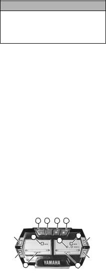
Speedometer/Tachometer/
Digital Gauge
|
A B |
C D |
|
Upper Left |
|
|
Upper Right |
G |
G |
Button |
|
Button |
|
||
H |
|
||
|
|
|
|
Lower Left |
|
|
Lower Right |
Button |
E |
F |
Button |
|
|
|
CWI-050A |
5
A. Coolant Temperature Indicator
The indicator and LOW TEMP display will cease to flash when the engine reaches proper operating temperature.
If the coolant temperature rises too far above proper operating temperature, the indicator will flash a warning (alert) and the engine will “surge” to alert the operator. If the coolant temperature rises to a critical point above proper operating temperature, the indicator will cease flashing and will remain constantly illuminated.
NOTE: If the indicator is constantly on, the engine will shut off if vehicle speed is reduced to 1.5 km-h (0.9 MPH) or slower.
CAUTION
If the indicator is illuminated, stop the engine immediately and allow it to cool down. If unable to either determine or remedy the problem, take the snowmobile to an authorized Yamaha Snowmobile dealer for service. If not under warranty, this service is at the discretion and expense of the snowmobile owner.
B. High Beam Indicator
The indicator is on whenever the high beam mode is selected by the headlight switch.
C. Oil Pressure Indicator
The indicator relates to engine oil pressure, not the oil level; however, if the oil level is low, it may affect oil pressure. If oil pressure is lost, check the oil level (see page 22).
If the indicator does not go out or if the engine does not start, take the snowmobile to an authorized Yamaha Snowmobile dealer. If not under warranty, this service is at the discretion and expense of the snowmobile owner.
D. Low Fuel Indicator
The indicator illuminates whenever the gas in the gas tank is low.
E. Coolant Temperature/Battery Voltage/Intake Air Temperature
This bar display shows coolant temperature, battery voltage, and intake air temperature. Press the Lower Left Button to change which parameter is being displayed. Press and hold the Lower Left Button to see the actual values associated with the mode selected.
F. Fuel Level Display
This display shows the approximate amount of gas remaining in the gas tank.
G. RPM/Speed/Clock/Altimeter
Press the Upper Left Button to cycle the left screen between RPM and speed.
NOTE: When RPM is displayed on the left screen, the right screen will display speed, clock, or altimeter. When speed is displayed on the left screen, the right screen will display RPM, clock, or altimeter.
Press the Upper Right Button to cycle the right screen between speed, RPM, clock, and altimeter.
Press and hold the Upper Button on the speed-side of the gauge to shift the gauge between standard (MPH/miles/fahrenheit) and metric (km/h/kilometers/celsius) modes.
Press and hold the Upper Button on the RPM-side of the gauge to view maximum RPM. This value is reset each time the ignition key is turned off.
With the clock mode selected by pressing the Upper Right Button, press and hold the Upper Right Button to set the clock. The option of selecting the 12-hour or 24-hour clock is available; press the either Left Button to alternate between the two modes. Next, press the Lower Right Button to set the clock. Press either Left Button to set the hours; then press the Lower Right Button to set the minutes. Press either Left Button to set the minutes. When the proper time has been set, press the Lower Right Button to return to the main gauge display.
6
With the altimeter mode selected by pressing the Upper Right Button, press and hold the Upper Right Button to set the current altitude by using either Left Button. When the proper altitude has been set, press the Lower Right Button to return to the main gauge display.
H. Engine Hour Meter/Odometer/ Trip Meter/Clock
This display shows engine hours, odometer, trip meter, or clock. Press the Lower Right Button to change which parameter is being displayed. The Engine Hour Meter and Odometer cannot be reset. To reset the trip meter, select the Trip Meter; then press and hold the Lower Right Button until the trip meter display reads 0.
NOTE: The clock can only be displayed in this position if it is not already being displayed in the main right screen. To set the clock when the clock is in this position, press and hold the Lower Right Button; then use the procedure found in G.
Diagnostic Codes
Diagnostic codes are activated by the ECM and may be displayed on the readout screen for a number of reasons.
If a code is displayed while the engine is running, the ECM is receiving input that is outside of its established parameters. If a code has been activated, take the snowmobile to an authorized Yamaha Snowmobile dealer for service. If not under warranty, this service is at the discretion and expense of the snowmobile owner.
Refer to the following chart for diagnostic codes.
Code |
Trouble |
P0031 |
O2 Heater Control Circuit Low |
|
|
P0032 |
O2 Heater Control Circuit High |
|
|
P0107 |
Manifold absolute pressure circuit low |
|
|
P0108 |
Manifold absolute pressure circuit |
|
high |
P0112 |
Intake air temp sensor circuit low |
P0113 |
Intake air temp sensor circuit high |
P0115 |
Engine coolant temp sensor 1 circuit |
P0117 |
Engine coolant temp sensor 1 circuit |
|
low |
P0118 |
Engine coolant temp sensor 1 circuit |
|
high |
P0120 |
Throttle position sensor circuit |
|
|
Code |
Trouble |
P0122 |
Throttle position sensor circuit low |
|
|
P0123 |
Throttle position sensor circuit high |
P0130 |
O2 sensor circuit |
|
|
P0131 |
O2 sensor circuit low |
P0132 |
O2 sensor circuit high |
|
|
P0171 |
System too lean |
P0172 |
System too rich |
|
|
P0201 |
Injector circuit/open - cylinder 1 |
P0202 |
Injector circuit/open - cylinder 2 |
|
|
P0203 |
Injector circuit/open - cylinder 3 |
P0217 |
Engine coolant over temp condition |
|
|
P0261 |
Cylinder 1 injector circuit low |
P0264 |
Cylinder 2 injector circuit low |
|
|
P0267 |
Cylinder 3 injector circuit low |
P0508 |
Idle air control system circuit low |
|
|
P0509 |
Idle air control system circuit high |
P0511 |
Idle air control circuit |
|
|
P0522 |
Engine oil pressure sensor circuit low |
P0523 |
Engine oil pressure sensor circuit high |
|
|
P0562 |
System voltage low |
P0563 |
System voltage high |
|
|
P0780 |
Shift Error |
P1315 |
Crankshaft Position out of sync |
|
|
P1338 |
Crankshaft spike detected |
P1339 |
Crankshaft tooth not detected |
|
|
P1685 |
Main relay open circuit |
P1686 |
Main relay circuit low |
|
|
P1688 |
Reverse relay open circuit |
P1689 |
Reverse relay circuit low |
|
|
P1691 |
Forward relay open circuit |
P1692 |
Forward relay circuit low |
|
|
P1694 |
Headlight relay open circuit |
P1695 |
Headlight relay circuit low |
|
|
P2228 |
Barometric pressure sensor A circuit |
|
low |
P2229 |
Barometric pressure sensor A circuit |
|
high |
P2300 |
Ignition coil A primary control circuit |
|
low |
P2303 |
Ignition coil B primary control circuit |
|
low |
P2306 |
Ignition coil C primary control circuit |
|
low |
U0155 |
Lost communication with the ECM |
7

Handlebar Tilt
(Mountain Models)
1.Loosen the four cap screws and tilt the handlebar to the desired position.
2.Adjust the handlebar to operator’s desired position, tighten the cap screws evenly to 2.0 kg-m (15 ft-lb), and check steering for maximum right/left turning capabilities.
Machine Screws
0748-905
2.Tighten the four cap screws evenly to 15 ft-lb.
 WARNING
Tighten the cap screws according to specifications to prevent unexpected “movement” of the handlebar during operation over rough terrain. DO NOT position handlebar so steering (maximum right/left turning capabilities) or throttle and brake controls are affected.
CAUTION
Do not rotate the handlebar to a position that allows air to enter the brake system.
 WARNING
Tighten cap screws according to specifications to prevent unexpected “movement” of the handlebar during operation over rough terrain. DO NOT position the handlebar so steering (maximum right/ left turning capabilities) or throttle and brake controls are affected.
Exhaust System
The exhaust system is designed to reduce noise and to improve the total performance of the engine. If any exhaust system component is removed from the engine and the engine is run, severe engine damage will result.
Handlebar Tilt (SR10 Models)
The handlebar can be adjusted to the operator’s preference. To adjust the handlebar, use the following procedure:
1.Remove the handlebar cover; then loosen the eight cap screws securing the handlebar caps to the riser and the riser to the steering post.
Cap Screws
Cap Screws
0747-828
Air-Intake Silencer
Used in conjunction with the fuel intake system is a specially designed air-intake silencer. The purpose of the silencer is to quiet the intake of fresh air. Since the fuel intake system is calibrated with the airintake silencer in place, the engine must never be run with the silencer removed. Performance will not be improved if the air-intake silencer is removed. In contrast, severe engine damage will occur.
CAUTION
These snowmobiles are not designed to be operated in dusty conditions. Operating the snowmobile in dusty conditions will result in severe engine damage.
8

Cooling System
These snowmobiles are equipped with a closed liquid cooling system for engine cooling. The cooling system should be inspected daily for leakage and damage. Also, the coolant level should be checked daily. If leakage or damage is detected, take the snowmobile to an authorized Yamaha Snowmobile dealer for service. If not under warranty, this service is at the discretion and expense of the snowmobile owner.
When filling the cooling system, use an ethylene glycol-based coolant/water mixture which will satisfy the coldest anticipated weather conditions of your area in accordance with the coolant manufacturer’s recommendations.
NOTE: If operating on ice or hardpacked snow conditions, it is recommended that Ice Scratchers be installed to reduce wear strip wear and engine overheating.
For checking/filling cooling system, refer to Coolant Level sub-section in the Maintenance section.
Battery
It is extremely important that the battery be maintained at full charge at all times and that the battery connections be clean and tight. If charging the battery becomes necessary, refer to Battery sub-section in the Maintenance section.
CAUTION
Always turn the ignition switch key to the OFF position when the snowmobile is not being used. Leaving the ignition switch in the ON position will result in discharging the battery and possible damage to the battery.
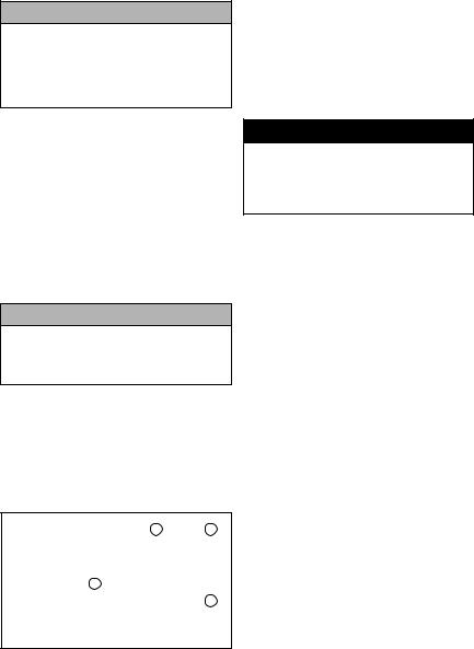
Jump-Starting
NOTE: Yamaha does not recommend jump-starting a snowmobile with a dead battery but rather to remove the battery, service it, and correctly charge it; however, in an emergency, it may be necessary to jump-start a snowmobile. If so, use the following procedure to carefully and safely complete this procedure.
 WARNING
Improper handling or connecting of a battery may result in severe injury including acid burns, electrical burns, or blindness as a result of an explosion. Always remove rings and watches. Any time service is performed on a battery, the following must be observed: keep sparks, open flame, cigarettes, or any other flame away. Always wear safety glasses. Protect skin and clothing when handling a battery. When servicing a battery in an enclosed space, keep the area well-venti- lated.
NOTE: To access the battery, the seat must be removed.
1.For the snowmobile to be jumpstarted, slide any terminal boots away.
2.Inspect the battery for any signs of electrolyte leaks, loose terminals, or bulging sides. Leaking or bulging battery cases may indicate a frozen or shorted battery.
 WARNING
If any of these conditions exist, DO NOT attempt to jump-start, boost, or charge the battery. An explosion could occur causing serious injury.
9
3.Inspect the snowmobile to be used for jump-starting to determine if voltage and ground polarity are compatible. The vehicle must have a 12-volt DC, negative ground electrical system.
CAUTION
Always make sure the electrical systems are of the same voltage and ground polarity prior to connecting jumper cables. If not, severe electrical damage may occur.
4.Move the vehicle to be used for the jump-start close enough to ensure the jumper cables easily reach; then set and lock the brakes, shut off all electrical accessories, and turn the ignition switch OFF.
NOTE: Make sure all switches on the snowmobile to be jump-started are turned OFF.
5.Disconnect all external accessories such as cell phones, GPS units, and radios on both vehicles.
CAUTION
Failure to disconnect electronic accessories during jump-starting may cause system damage due to power spikes.
6.Attach one clamp of the positive (red) cable to the positive (+) terminal (1) of the dead battery (C) being careful not to touch any metal with the other clamp; then attach the other clamp of the positive (red) cable to the positive (+) terminal (2) of the good battery (B).
A. Unpainted Surface on Engine |
3 |
2 |
B.Good Battery
C.Dead Battery
B
4
1
A C
0744-527
NOTE: Some jumper cables may be the same color but the clamps or ends will be color-coded red and black.
7.Attach one clamp of the negative jumper cable (black) to the negative (-) terminal (3) of the good battery (B); then attach the other clamp of the negative (black) jumper cable (4) to an unpainted metal surface (A) on the engine or frame well away from the dead battery and fuel system components.
 WARNING
Never make the final connection to a battery as a spark could ignite hydrogen gases causing an explosion of the battery resulting in acid burns or blindness.
8.Stand well away from the dead battery and start the vehicle with the good battery. Allow the vehicle to run for several minutes applying some charge to the dead battery.
9.Start the snowmobile with the dead battery and allow it to run for several minutes before disconnecting the jumper cables.
10.Remove the jumper cables in opposite order of hook-up (4, 3, 2, 1). Be careful not to short cables against bare metal.
NOTE: Have the battery and electrical system checked prior to operating the snowmobile again.
Drive Clutch and Driven Clutch
The drive clutch and driven clutch do not require lubrication; therefore, no special maintenance is required by the snowmobile owner except for periodical cleaning.
However, the drive clutch and driven clutch should be disassembled, cleaned, and inspected by an authorized Yamaha Snowmobile dealer after every 4000 km (2500 miles) or seasonally, whichever occurs first. This service is at the discretion and expense of the snowmobile owner.
10
When operating the snowmobile at high altitudes, it may be necessary to change certain component parts of the drive clutch and/or the driven clutch. See an authorized Yamaha Snowmobile dealer for further information.
CAUTION
DO NOT attempt to service the drive clutch and driven clutch. The drive clutch and driven clutch must be serviced by an authorized Yamaha Snowmobile dealer only.
Drive Clutch/Driven Clutch Alignment
The alignment between the drive clutch and driven clutch is set at the factory. Normally, no adjustment is necessary as long as neither the drive clutch nor the driven clutch is removed or disassembled. However, if premature drive belt wear is experienced or if the drive belt turns over, the drive clutch/driven clutch alignment must be checked. Take the snowmobile to an authorized Yamaha Snowmobile dealer for this service. If not under warranty, this service is at the discretion and expense of the snowmobile owner.
Fuel Pump
The fuel pump is designed to provide adequate amount of gas to the injectors at all throttle settings. If a fuel delivery problem is suspected, take the snowmobile to an authorized Yamaha Snowmobile dealer. If not under warranty, this service is at the discretion and expense of the snowmobile owner.
Shock Absorbers
(Rebuildable Gas)
Each shock absorber should be visibly checked weekly for fluid leakage, cracks or breaks in the body/reservoir, or a bent shaft. If any one of these conditions is detected, replacement or service is necessary. Take the snowmobile to an authorized Yamaha Snowmobile dealer for this service. If not under warranty, this service is at the discretion and expense of the snowmobile owner.
NOTE: When the snowmobile is operated in extremely cold weather (-23°C/-10°F or colder), a small amount of leakage may be present. Unless the leakage is excessive, replacement is not necessary.
NOTE: The frequency of servicing rebuildable shock absorbers will vary according to the types of conditions and terrain the snowmobile has been subjected to. If riding quality deteriorates (or seems to be deteriorating), take the snowmobile to an authorized Yamaha Snowmobile dealer for shock absorber evaluation and/or servicing. This service is at the discretion and expense of the snowmobile owner.
Track/Track Studs
Accelerated wear strip and track clip wear caused by operating on ice or hardpacked snow conditions is NOT covered under Yamaha warranty policy.
NOTE: If regularly operating on ice or hard-packed snow conditions, Performance Wear Strips may be installed at the expense of the snowmobile owner.
In general, track life will be shortened when studs are installed. Drilling stud holes into the drive track will cut the internal fibers weakening the track. Avoid spinning the drive track. Studs may catch on an object and pull out of the track leaving tears and damage around the already weakened area. To minimize possible damage, consult your stud manufacturer for installation and stud pattern recommendations. Yamaha does not recommend studding a track.
11
Paddle Track (On Equipped Models)
These models are equipped with a Power Claw style track which is specially designed for use in powder snow riding conditions. When the Power Claw track is operated in hard-packed snow conditions, it will run slightly slower than a standard track and it will accelerate wear strip wear. To decrease the amount of wear strip wear, slower speeds must be maintained when operating on hardpacked trails. Accelerated wear strip wear caused by operating a Power Claw track on hard-packed snow conditions is NOT covered under Yamaha warranty policy.
NOTE: If operating on ice or hardpacked snow conditions, it is recommended that Ice Scratchers be installed to reduce wear strip wear and engine overheating.
1.Always warm up the engine for 2-3 minutes prior to shifting into reverse.
2.With the engine at idle (under 2500 RPM) and the snowmobile at a complete stop, press and release the reverse switch button.
NOTE: The snowmobile must be at a complete stop and the engine running under 2500 RPM before the system will allow shifting.
3.When reverse is engaged, a reverse icon will illuminate on the deluxe digital gauge and a reverse alarm will sound.
CAUTION
Never shift into reverse while the snowmobile is moving forward as it is hard on the drive system.
Operating in Reverse
Reverse Operation
The electrical reverse function offers the operator the convenience of being able to back up the snowmobile rather than having to turn the snowmobile around by hand. This feature, under most situations, should not be used to free a stuck snowmobile as it will tend to dig the skis deeper into the snow. Always use minimal speed when operating in reverse and come to a complete stop before shifting from either forward to reverse or reverse to forward.
Shifting Into Reverse
Reverse Switch Button
741-438A
NOTE: Correct drive belt tension
(deflection) is important for the reverse function to operate properly. If the belt is too tight, difficulty in engaging reverse will be experienced.
 WARNING
Use caution and minimal speed when operating the snowmobile in reverse. Be sure the button is in the desired position.
1.When shifting into reverse, always wait for the reverse icon to illuminate and the reverse alarm to sound before backing up.
NOTE: The reverse function is cancelled whenever the engine is shut off.
2.After shifting from reverse to forward (or from forward to reverse), apply the throttle slowly and evenly to allow the driven pulley to engage properly.
CAUTION
After reversing in deep powder snow conditions, make sure the snowflap does not become “caught up” in the track. Track and/or snowflap damage may occur.
CAUTION
If the snowmobile is equipped with ice scratchers, the scratchers must be disengaged or component damage will occur.
12
Loading...