


WORLD WIDE
40V, 50H
USA/CANADA
40W, 50W
SERVICE
MANUAL
LIT-18616-01-81 |
290320 |

E
A20000-0
NOTICE
This manual has been prepared by the Yamaha Motor Company primarily for use by Yamaha dealers and their trained mechanics when performing maintenance procedures and repairs to Yamaha equipment. It has been written to suit the needs of persons who have a basic understanding of the mechanical and electrical concepts and procedures inherent in the work, for without such knowledge attempted repairs or service to the equipment could render it unsafe or unfit for use.
Because the Yamaha Motor Company Ltd. has a policy of continuously improving its products, models may differ in detail from the descriptions and illustrations given in this publication. Use only the latest edition of this manual. Authorized Yamaha dealers are notified periodically of modifications and significant changes in specifications and procedures, and these are incorporated in successive editions of this manual.
A10001-0*
40V/50H SERVICE MANUAL
1997 Yamaha Motor Corporation, USA
1st Edition, August 1997 All rights reserved.
No part of this publication may be reproduced or transmitted in any form or by any means including photocopying and recording without the written permission of the copyright holder.
Such written permission must also be obtained before any part of this publication is stored in a retrieval system of any nature. Printed in U.S.A.
LIT-18616-01-81

E
HOW TO USE THIS MANUAL
MANUAL FORMAT
All of the procedures in this manual are organized in a sequential, step-by-step format. The information has been complied to provide the mechanic with an easy to read, handy reference that contains comprehensive explanations of all disassembly, repair, assembly, and inspection operations.
In this revised format, the condition of a faulty component will precede an arrow symbol and the course of action required will follow the symbol, e.g.,
●Bearings
Pitting/Damage → Replace.
To assist you to find your way about this manual, the Section Title and Major Heading is given at the head of every page.
An Index to contents is provided on the first page of each Section.
MODEL INDICATION
Multiple models are shown in this manual. These indications are noted as follows.
Model name |
40VMH |
40VMHD |
40VMHO |
40VMO |
40VWH |
40VE |
40VEO |
40VEHTO |
40VET |
|
|
|
|
|
|
|
|
|
|
USA and |
C40MH |
|
40MH |
|
|
C40ER |
40ER |
P40TH |
C40TR |
CANADA name |
|
|
|
||||||
|
|
|
|
|
|
|
|
|
|
|
|
|
|
|
|
|
|
|
|
Indication |
40VMH |
40VMHD |
40VMHO |
40VMO |
40VWH |
40VE |
40VEO |
40VEHTO |
40VET |
|
|
|
|
|
|
|
|
|
|
Model name |
40VETO |
50HMHO |
50HMHD |
50HMO |
50HMDO |
50HWHD |
50HEDO |
50HET |
50HETO |
|
|
|
|
|
|
|
|
|
|
USA and |
40TR |
|
|
|
|
|
50ER |
C50TR |
50TR |
CANADA name |
|
|
|
|
|
||||
|
|
|
|
|
|
|
|
|
|
|
|
|
|
|
|
|
|
|
|
Indication |
40VETO |
50HMHO |
50HMHD |
50HMO |
50HMDO |
50HWHD |
50HEDO |
50HET |
50HETO |
|
|
|
|
|
|
|
|
|
|
THE ILLUSTRATIONS
Some illustrations in this manual may differ from the model you have. This is because a procedure described may relate to several models, though only one may be illustrated. (The name of model described will be mentioned in the description).
REFERENCES
These have been kept to a minimum; however, when you are referred to another section of the manual, you are told the page number to go to.

E
WARNINGS, CAUTIONS AND NOTES
Attention is drawn to the various Warnings, Cautions and Notes which distinguish important information in this manual in the following ways.
 The Safety Alert Symbol means ATTENTION! BECOME ALERT! YOUR SAFETY IS INVOLVED!
 WARNING
Failure to follow WARNING instructions could result in severe injury or death to the machine operator, a bystander, or a person inspecting or repairing the outboard motor.
CAUTION:
A CAUTION indicates special precautions that must be taken to avoid damage to the outboard motor.
NOTE:
A NOTE provides key information to make procedures easier or clearer.
SPECIFICATIONS
These are given in bold type at each procedure. It is not necessary to leave the section dealing with the procedure in order to look up the specifications.
It is important to note the differences in specifications of models. When a procedure relates to more than one model, the main differences in specifications will be shown in a following table.
Model name |
40VMH |
40VMHD |
40VMHO |
40VMO |
40VWH |
40VE |
40VEO |
40VEHTO |
40VET |
|
|
|
|
|
|
|
|
|
|
|
|
Starting system |
Manual |
Manual |
Manual |
Manual |
Manual |
Electric |
Electric |
Electric |
Electric |
|
& Electric |
||||||||||
|
|
|
|
|
|
|
|
|
||
Control system |
Tiller |
Tiller |
Tiller |
Remote |
Tiller |
Remote |
Remote |
Tiller |
Remote |
|
|
|
|
|
|
|
|
|
|
|
|
Trim/Tilt system |
Manual tilt |
Hydro tilt |
Manual tilt |
Manual tilt |
Hydro tilt |
Manual tilt |
Manual tilt |
PTT |
PTT |
|
|
|
|
|
|
|
|
|
|
|
|
Lubrication system |
Pre-Mixed |
Pre-Mixed |
Oil injection |
Oil injection |
Pre-Mixed |
Pre-Mixed |
Oil injection |
Oil injection |
Pre-Mixed |
|
|
|
|
|
|
|
|
|
|
|
|
Warning indicator |
1 |
1 |
1 |
1 |
1 |
1 |
3 |
— |
— |
|
lamp |
||||||||||
|
|
|
|
|
|
|
|
|
||
Enrichment system |
Choke |
Choke |
Choke |
Choke |
Prime Start |
Prime Start |
Prime Start |
Prime Start |
Prime Start |
|
|
|
|
|
|
|
|
|
|
|
|
Model name |
40VETO |
50HMHO |
50HMHD |
50HMO |
50HMDO |
50HWHD |
50HEDO |
50HET |
50HETO |
|
|
|
|
|
|
|
|
|
|
|
|
Starting system |
Electric |
Manual |
Manual |
Manual |
Manual |
Manual & |
Electric |
Electric |
Electric |
|
Electric |
||||||||||
|
|
|
|
|
|
|
|
|
||
Control system |
Remote |
Tiller |
Tiller |
Remote |
Remote |
Tiller |
Remote |
Remote |
Remote |
|
|
|
|
|
|
|
|
|
|
|
|
Trim/Tilt system |
PTT |
Manual tilt |
Hydro tilt |
Manual tilt |
Hydro tilt |
Hydro tilt |
Hydro tilt |
PTT |
PTT |
|
|
|
|
|
|
|
|
|
|
|
|
Lubrication system |
Oil injection |
Oil injection |
Pre-Mixed |
Oil injection |
Oil injection |
Pre-Mixed |
Oil injection |
Oil injection |
Oil injection |
|
|
|
|
|
|
|
|
|
|
|
|
Warning indicator |
3 |
1 |
1 |
1 |
1 |
1 |
3 |
— |
— |
|
lamp |
||||||||||
|
|
|
|
|
|
|
|
|
||
|
|
|
|
|
|
|
|
|
|
|
Enrichment system |
Prime Start |
Choke |
Choke |
Choke |
Choke |
Prime Start |
Prime Start |
Prime Start |
Prime Start |
|
|
|
|
|
|
|
|
|
|
|
E
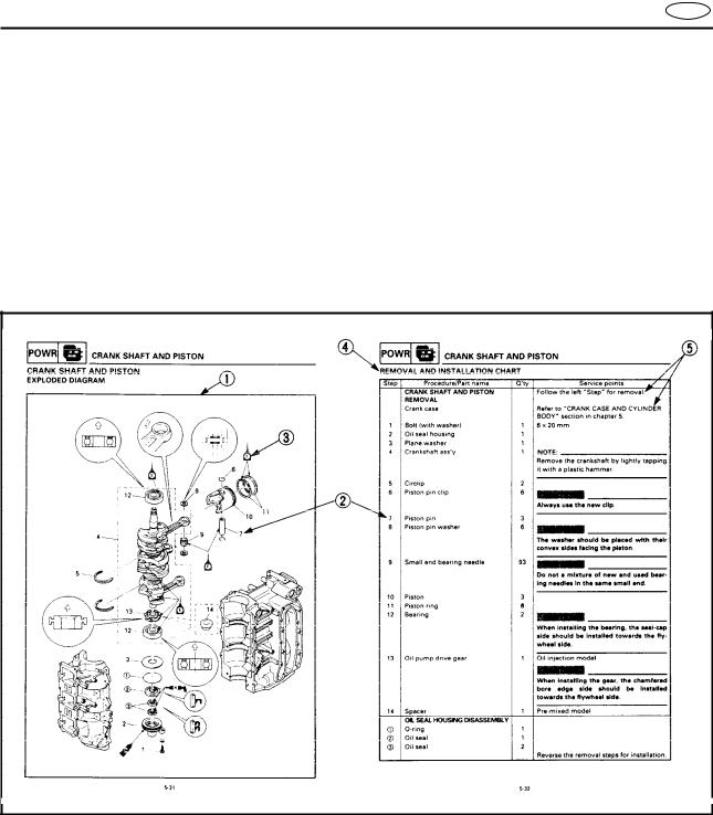
HOW TO READ DESCRIPTIONS
1.A disassembly installation job mainly consists of the exploded diagram 1.
2.The numerical figures represented by the number 2 indicates the order of the job steps.
3.The symbols represented by the number 3 indicates the contents and notes of the job. For the meanings of the symbols, refer to the next page(s).
4.The REMOVAL AND INSTALLATION CHART 4 is attached to the exploded diagram and explains the job steps, part names, notes for the jobs, etc.
5.The SERVICE POINTS, other than the exploded diagram, explains in detail the items difficult to explain in the exploded diagram or REMOVAL AND INSTALLATION CHART, the Service points requiring the detailed description 5, etc.
E
1 |
2 |
|
|
GEN |
SPEC |
|
|
INFO |
|
|
|
|
|
|
|
3 |
4 |
|
|
INSP |
FUEL |
|
|
ADJ |
|
|
|
|
|
|
|
5 |
6 |
|
|
POWR |
LOWR |
|
|
7 |
8 |
|
|
BRKT |
ELEC |
– |
+ |
9 |
0 |
|
|
TRBL |
|
|
|
ANLS |
|
|
|
A |
B |
|
|
C |
D |
|
|
|
|
T |
|
|
|
. |
|
|
|
R |
|
|
|
. |
|
E |
F |
|
|
G |
H |
|
|
E |
G |
|
|
I |
J |
|
|
|
A |
|
|
M |
|
|
|
K |
L |
|
|
GM |
LT |
|
|
|
271 |
|
|
M |
N |
|
|
LT |
LT |
|
|
242 |
572 |
|
|
A50001-1-4
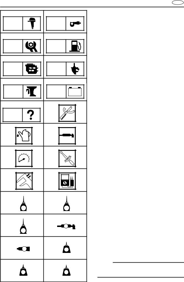
SYMBOLS
Symbols 1 to 9 are designed as thumbtabs to indicate the content of a chapter.
1 General Information
2 Specifications
3 Periodic Inspection and Adjustment
4 Fuel System
5 Power Unit
6 Lower Unit
7 Bracket Unit
8 Electrical System
9 Trouble-analysis
Symbols 0 to F indicate specific data:
0 Special tool
A Specified liquid B Specified grease
C Specified engine speed D Specified torque
E Specified measurement
FSpecified electrical value
[Resistance (Ω), Voltage (V), Electric current (A)]
Symbol G to J in an exploded diagram indicate grade of lubricant and location of lubrication point:
G Apply Yamaha 2-stroke outboard motor oil H Apply Yamaha gear-case lubricant
I Apply molybdenum disulfide oil
JApply water resistant grease (Yamaha grease A, Yamaha marine grease)
Symbols K to N in an exploded diagram indicate grade of sealing or locking agent, and location of application point:
K Apply Gasket maker
L Apply LOCTITE No. 271 (Red LOCTITE) M Apply LOCTITE No. 242 (Blue LOCTITE) N Apply LOCTITE No. 572
NOTE:
In this manual, the above symbols may not be used in every case.

|
INDEX |
E |
|
A30000-0 |
|
|
|
|
|
|
|
GENERAL INFORMATION |
INFOGEN |
1 |
|
|
|
||
SPECIFICATIONS |
SPEC |
2 |
|
|
|
||
PERIODIC INSPECTION AND |
|
3 |
|
ADJUSTMENT |
INSPADJ |
||
FUEL SYSTEM |
FUEL |
4 |
|
|
|
||
POWER UNIT |
|
POWR 5 |
|
|
|
||
LOWER UNIT |
|
LOWER 6 |
|
|
|
||
BRACKET UNIT |
BRKT |
7 |
|
|
|
||
|
|
– + |
8 |
ELECTRICAL SYSTEM |
ELEC |
||
|
|
||
TROUBLE-ANALYSIS |
ANLSTRBL |
9 |
|
|
|
||
|
|
|
|
|
|
GEN |
|
|
|
|
INFO |
|
|
E |
|
|
|
|
|
|
|
|
|
CHAPTER 1 |
|
|
|
|
|
|
|
|
|
GENERAL INFORMATION |
IDENTIFICATION............................................................................................. |
1-1 |
SERIAL NUMBER ..................................................................................... |
1-1 |
STARTING SERIAL NUMBERS ............................................................... |
1-1 |
SAFETY WHILE WORKING ............................................................................ |
1-2 |
FIRE PREVENTION ................................................................................... |
1-2 |
VENTILATION........................................................................................... |
1-2 |
SELF-PROTECTION.................................................................................. |
1-2 |
OILS, GREASES AND SEALING FLUIDS................................................ |
1-2 |
GOOD WORKING PRACTICES ................................................................ |
1-3 |
DISASSEMBLY AND ASSEMBLY ........................................................... |
1-4 |
SPECIAL TOOLS ............................................................................................. |
1-5 |
MEASURING ............................................................................................ |
1-6 |
REMOVAL AND INSTALLATION ............................................................ |
1-8 |
1
2
3
4
5
6
7
8
9
GEN INFO
IDENTIFICATION |
E |
A60000-1*
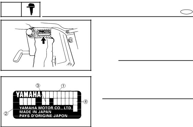
IDENTIFICATION
SERIAL NUMBER
The serial number of the outboard motor is stamped on a plate attached to the port side of the clamp bracket.
NOTE:
As an antitheft measure, a special label on which the outboard motor serial number is stamped is bonded to the portside of the clamp bracket. The label is specially treated so that peeling it off causes cracks across the serial number.
1 Model name
2 Approved model No.
3 Transom height
4 Serial number
STARTING SERIAL NUMBERS
The starting serial number blocks are as follows:
Model |
Approved |
Starting |
Model |
Approved |
Starting |
||||
World- |
USA, |
model |
World- |
USA, |
model |
||||
serial No. |
serial No. |
||||||||
wide |
CANADA |
code |
wide |
CANADA |
code |
||||
|
|
|
|||||||
|
|
|
|
|
|
|
|
||
40VMH |
C40MH |
|
S: 010262 ~ |
50HMHO |
— |
|
S: 190662 ~ |
||
|
|
|
|
|
|
|
|||
|
L: 310801 ~ |
50HMHD |
— |
|
L: 310380 ~ |
||||
|
|
|
|
||||||
|
|
|
|
|
|
|
|
||
40VMHD |
— |
|
L: 560290 ~ |
50HMO |
— |
|
S: 260189 ~ |
||
|
|
|
|
|
|
|
|
||
40VMHO |
40MH |
|
S: 191877 ~ |
50HMDO |
— |
|
L: 560258 ~ |
||
|
|
|
|
|
|
|
|||
|
L: 491566 ~ |
50HWHD |
— |
|
L: 850194 ~ |
||||
|
|
|
|
||||||
|
|
|
|
|
|
|
|
||
40VMO |
— |
|
S: 290284 ~ |
50HEDO |
50ER |
6H5 |
S: 090431 ~ |
||
|
L: 860312 ~ |
|
L: 521079 ~ |
||||||
|
|
|
|
|
|
||||
|
|
|
|
|
|
|
|
||
40VWH |
— |
|
L: 510116 ~ |
50HET |
C50TR |
|
L: 900101 ~ |
||
|
|
|
|
|
|
|
|
||
40VE |
C40ER |
6H4 |
S: 060285 ~ |
|
|
|
S: 210142 ~ |
||
L: 360173 ~ |
50HETO |
50TR |
|
L: 444058 ~ |
|||||
|
|
|
|
||||||
|
|
|
|
|
|
|
|
||
|
|
|
S: 110760 ~ |
|
|
|
X: 750216 ~ |
||
40VEO |
40ER |
|
L: 842362 ~ |
|
|
|
|
|
|
|
|
|
|
|
|
||||
|
|
|
X: 740146 ~ |
|
|
|
|
|
|
|
|
|
|
|
|
|
|
|
|
40VEHTO |
P40TH |
|
L: 430386 ~ |
|
|
|
|
|
|
|
|
|
|
|
|
|
|
|
|
40VET |
C40TR |
|
L: 921505 ~ |
|
|
|
|
|
|
|
|
|
|
|
|
|
|
|
|
|
|
|
S: 880367 ~ |
|
|
|
|
|
|
40VETO |
40TR |
|
L: 544974 ~ |
|
|
|
|
|
|
|
|
|
X: 900196 ~ |
|
|
|
|
|
|
|
|
|
|
|
|
|
|
|
|
1-1
GEN INFO
SAFETY WHILE WORKING |
E |
SAFETY WHILE WORKING
The procedures given in this manual are those recommended by Yamaha to be followed by Yamaha dealers and their mechanics.
FIRE PREVENTION
Gasoline (petrol) is highly flammable. Petroleum vapor is explosive if ignited.
Do not smoke while handling, and keep it away from heat, sparks, and open flames.
VENTILATION
Petroleum vapor is heavier than air and is deadly if inhaled in large quantities. Engine exhaust gases are harmful to breathe. When test-running an engine indoors, maintain good ventilation.
SELF-PROTECTION
Protect your eyes with suitable safety glasses or safety goggles when using compressed air, when grinding or when doing any operation which may cause particles to fly off. Protect hands and feet by wearing safety gloves or protective shoes if appropriate to the work you are doing.
OILS, GREASES AND SEALING FLUIDS
Use only genuine Yamaha oils, greases and sealing fluids or those recommended by Yamaha.
1-2
GEN INFO
SAFETY WHILE WORKING |
E |
Under normal conditions of use, there should be no hazards from the use of the lubricants mentioned in this manual, but safety is all-important, and by adopting good safety practices, any risk is minimized.
A summary of the most important precautions is as follows:
1.While working, maintain good standards of personal and industrial hygiene.
2.Clothing which has become contaminated with lubricants should be changed as soon as practicable, and laundered before further use.
3.Avoid skin contact with lubricants; do not, for example, place a soiled wipingrag in one’s pocket.
4.Hands and any other part of the body which have been in contact with lubricants or lubricant-contaminated clothing, should be thoroughly washed with hot water and soap as soon as practicable.
5.To protect the skin, the application of a suitable barrier cream to the hands before working is recommended.
6.A supply of clean lint-free cloths should be available for wiping purposes.
GOOD WORKING PRACTICES
1.The right tools
Use the special tools that are advised to protect parts from damage. Use the right tool in the right manner — don’t improvise.
2.Tightening torque
Follow the torque tightening instructions. When tightening bolts, nuts and screws, tighten the large sizes first, and tighten inner-positioned fixings before outer-positioned ones.
1-3
GEN INFO
SAFETY WHILE WORKING |
E |
3.Non-reusable items
Always use new gaskets, packings, O- rings, split-pins and circlips etc. on reassembly.
DISASSEMBLY AND ASSEMBLY
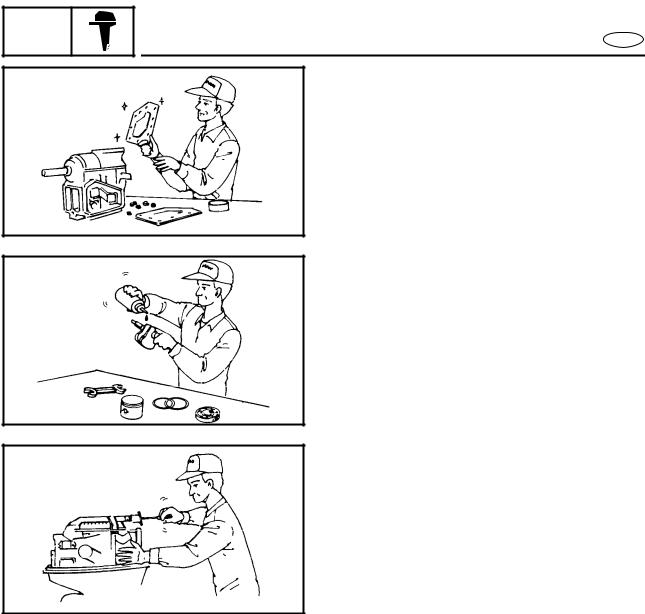
1.Clean parts with compressed-air on disassembling them.
2.Oil the contact surfaces of moving parts on assembly.
3.After assembly, check that moving parts operate normally.
4.Install bearings with the manufacturer’s markings on the side exposed to view, and liberally oil the bearings.
5.When installing oil seals, apply a light coating of water-resistant grease to the outside diameter.
1-4
GEN INFO
SPECIAL TOOLS
E
A80000-0*
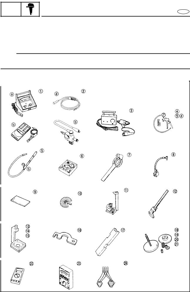
SPECIAL TOOLS
The use of correct special tools recommended by Yamaha will aid the work and enable accurate assembly and tune-up. Improvisations and use of improper tools can cause damage to the equipment.
NOTE:
●For U.S.A. and Canada, use part number starting with “YB-”, “YU-” or “YW-”.
●For others, use part number starting with “90890-”.
1-5

|
|
|
|
|
|
|
|
|
|
|
|
GEN |
|
|
|
SPECIAL TOOLS |
|
|
|
||
|
INFO |
|
|
|
|
|
E |
|||
|
MEASURING |
|
|
|
|
|
||||
|
|
|
|
|
|
|
|
|
|
|
|
|
|
|
|
|
|
Tool No. |
|
|
|
|
|
|
Tool name |
USA and |
Except for |
Use for: |
||||
|
|
|
USA and |
|||||||
|
|
|
|
|
|
|
Canada a |
|
|
|
|
|
|
|
|
|
|
Canada b |
|
|
|
|
|
|
|
|
|
|
||||
|
1 |
Tachometer |
|
YU-08036-A |
90890-06760 |
Idle speed |
||||
|
|
|
|
|
|
|||||
|
2 |
Dynamic spark tester |
YM-34487 |
90890-06754 |
Ignition system |
|||||
|
|
|
|
|
|
|
||||
|
3 |
C.D.I. tester |
|
YU-91022-B |
N.A. |
Ignition system |
||||
|
|
|
|
|
|
|
||||
|
4 |
Mity Vac |
|
YB-35956 |
90890-06756 |
Fuel joint |
||||
|
|
|
|
|
|
|||||
|
5 |
Pressure tester |
YB-35956 |
90890-06762 |
Lower case |
|||||
|
|
|
|
|
|
|||||
|
6 |
Dial indicator |
YU-03097 |
90890-01252 |
Backlash |
|||||
|
|
|
|
|
|
|||||
|
7 |
Backlash indicator |
YB-06265 |
90890-06706 |
Backlash |
|||||
|
|
|
|
|
|
|||||
|
8 |
Magnetic flexible stand |
YU-34481 |
90890-06705 |
Backlash |
|||||
|
|
|
|
|
|
|||||
|
9 |
Backlash adjusting plate |
YB-07003 |
N.A. |
Backlash |
|||||
|
|
|
|
|
|
|||||
|
10 |
Thickness gauge |
YU-26900-9 |
N.A. |
Shimming |
|||||
|
|
|
|
|
|
|||||
|
11 |
Pinion height gauge |
N.A. |
90890-06702 |
Pinion shimming |
|||||
|
|
|
|
|
|
|
|
|
|
|
|
12 |
Digital caliper |
N.A. |
90890-06704 |
Pinion |
Forward |
||||
|
shimming |
shimming |
||||||||
|
|
|
|
|
|
|
|
|
||
|
|
|
|
|
|
|
|
|||
|
13 |
Gauge block |
|
YB-34432-9 |
N.A. |
Pinion |
shimming |
|||
|
|
|
|
|
|
|||||
|
14 |
Adapter plate |
YB-34432-10 |
N.A. |
Pinion shimming |
|||||
|
|
|
|
|
|
|
||||
|
15 |
Gauge base |
|
YB-34432-11 |
N.A. |
Pinion shimming |
||||
|
|
|
|
|
|
|
||||
|
16 |
Clamp |
|
YB-34432-17 |
N.A. |
Pinion shimming |
||||
|
|
|
|
|
|
|||||
|
17 |
Shimming plate |
N.A. |
90890-06701 |
Forward shimming |
|||||
|
|
|
|
|
|
|
||||
|
18 |
Base plate |
|
YB-34446-1 |
N.A. |
Forward shimming |
||||
|
|
|
|
|
|
|||||
|
19 |
Compression spring |
YB-34446-3 |
N.A. |
Forward shimming |
|||||
|
|
|
|
|
|
|
||||
|
20 |
Press plate |
|
YB-34446-4 |
N.A. |
Forward shimming |
||||
|
|
|
|
|
|
|
||||
|
21 |
Gauge pin |
|
YB-34446-7 |
N.A. |
Forward shimming |
||||
|
|
|
|
|
|
|||||
|
22 |
Digital multimeter |
YU-34899-A |
90890-06752 |
Electrical |
|||||
|
|
|
|
|
|
|||||
|
23 |
Pocket tester |
YU-03112 |
90890-03112 |
Electrical |
|||||
|
|
|
|
|
|
|||||
|
24 |
Spins test harness |
YB-06757 |
90890-06757 |
Peak voltage measurement |
|||||
|
|
|
|
|
|
|
|
|
|
|
1-6

GEN INFO
SPECIAL TOOLS
E
1-7

GEN INFO
SPECIAL TOOLS
E
REMOVAL AND INSTALLATION
|
|
Tool No. |
|
|
||
|
Tool name |
USA and |
Except for |
Use for: |
||
|
USA and |
|||||
|
|
Canada a |
|
|
||
|
|
Canada b |
|
|
||
|
|
|
|
|
|
|
1 |
Small end bearing |
YB-06106 |
90890-06526 |
Small end |
||
needle installer |
||||||
|
|
|
|
|
||
|
|
|
|
|
|
|
|
|
|
|
|
Reverse gear |
|
|
|
|
|
Crank shaft |
bearing |
|
2 |
Bearing separator |
YB-06219 |
90890-06534 |
|
||
Forward |
||||||
|
|
|
|
bearing |
gear inner |
|
|
|
|
|
|
||
|
|
|
|
|
bearing |
|
|
|
|
|
|
|
|
3 |
Flywheel holder |
YB-06139 |
90890-06522 |
Flywheel |
||
|
|
|
|
|
||
4 |
Flywheel puller |
YB-06117 |
90890-06521 |
Flywheel |
||
|
|
|
|
|
|
|
|
|
|
|
|
Reverse gear |
|
5 |
Stopper guide plate |
N.A. |
90890-06501 |
Propeller |
bearing |
|
shaft housing |
Drive shaft |
|||||
|
|
|
|
|
outer bearing |
|
|
|
|
|
|
|
|
6 |
Bearing housing puller |
YB-06234 |
90890-06503 |
Propeller shaft housing |
||
|
|
|
|
|
||
7 |
Center bolt |
N.A. |
90890-06504 |
Propeller shaft housing |
||
|
|
|
|
|
||
8 |
Universal puller |
YB-06117 |
N.A. |
Propeller shaft housing |
||
|
|
|
|
|
||
9 |
Oil seal installer |
YB-06168 |
N.A. |
Propeller shaft oil seal |
||
|
|
|
|
|
||
10 |
Needle bearing remover |
YB-06112 |
90890-06614 |
Propeller shaft |
||
needle bearing |
||||||
|
|
|
|
|||
|
|
|
|
|
||
11 |
Needle bearing installer |
YB-06111 |
90890-06614 |
Propeller shaft |
||
needle bearing |
||||||
|
|
|
|
|||
|
|
|
|
|
|
|
12 |
Bearing outer race puller |
N.A. |
90890-06535 |
Reverse gear bearing |
||
clow |
||||||
|
|
|
|
|
||
|
|
|
|
|
|
|
|
|
|
|
Reverse gear |
Forward |
|
13 |
Stopper guide stand |
N.A. |
90890-06538 |
gear outer |
||
|
|
|
|
bearing |
bearing |
|
|
|
|
|
|
||
|
|
|
|
|
|
|
|
|
|
|
|
Drive shaft |
|
|
|
|
|
Reverse gear |
outer bearing |
|
14 |
Slide hammer set |
YB-06096 |
N.A. |
|
||
Forward |
||||||
|
|
|
|
bearing |
gear outer |
|
|
|
|
|
|
||
|
|
|
|
|
bearing |
|
|
|
|
|
|
|
|
15 |
Pinion nut wrench |
N.A. |
90890-06505 |
Pinion |
nut |
|
|
|
|
|
|
||
16 |
Socket adapter |
N.A. |
90890-06506 |
Pinion nut |
||
|
|
|
|
|
||
17 |
Drive shaft holder |
YB-06079 |
90890-06517 |
Pinion nut |
||
|
|
|
|
|
|
|
18 |
Needle bearing attach- |
YB-06063 |
90890-06614 |
Drive shaft needle bearing |
||
ment |
||||||
|
|
|
|
|
||
|
|
|
|
|
|
|
19 |
Drive shaft needle bear- |
YB-34473 |
N.A. |
Drive shaft needle bearing |
||
ing depth stop |
||||||
|
|
|
|
|
||
|
|
|
|
|
||
20 |
Bearing installer |
YB-06167 |
90890-06628 |
Drive shaft oil seal |
||
|
|
|
|
|
||
21 |
Bearing installer |
YB-06110 |
90890-06627 |
Drive shaft outer bearing |
||
|
|
|
|
|
||
22 |
Bearing installer |
YB-06270-A |
90890-06640 |
Forward gear inner bearing |
||
|
|
|
|
|
|
|
1-8

GEN INFO
SPECIAL TOOLS
E
1-9

GEN INFO
SPECIAL TOOLS
E
|
|
Tool No. |
|
|
||
|
Tool name |
USA and |
Except for |
Use for: |
||
|
USA and |
|||||
|
|
Canada a |
|
|
||
|
|
Canada b |
|
|
||
|
|
|
|
|
||
23 |
Bearing outer race puller |
N.A. |
90890-06523 |
Forward gear outer bearing |
||
|
|
|
|
|
|
|
24 |
Bearing outer race puller |
N.A. |
90890-06532 |
Forward gear outer bearing |
||
clow |
||||||
|
|
|
|
|
||
|
|
|
|
|
||
25 |
Bearing installer |
YB-41446 |
90890-06626 |
Forward gear outer bearing |
||
|
|
|
|
|
||
26 |
Shift rod wrench |
YB-06052 |
N.A. |
Shift rod |
||
|
|
|
|
PTT |
||
27 |
Tilt cylinder wrench |
YB-06175-2B |
90890-06544 |
|||
|
|
|
|
|
|
|
|
|
|
|
Propeller |
Drive shaft |
|
28 |
Bearing depth plate |
N.A. |
90890-06603 |
shaft needle |
needle bear- |
|
|
|
|
|
bearing |
ing |
|
|
|
|
|
|
|
|
29 |
Driver rod - SL |
N.A. |
90890-06602 |
Drive shaft |
needle bearing |
|
|
|
|
|
|
||
30 |
Driver rod - SS |
N.A. |
90890-06604 |
Propeller shaft |
||
needle bearing |
||||||
|
|
|
|
|||
|
|
|
|
|
||
31 |
Driver rod - L |
YB-06071 |
90890-06605 |
Bearing and oil seal |
||
|
|
|
|
|
||
32 |
Driver rod - S |
N.A. |
90890-06606 |
Bearing and oil seal |
||
|
|
|
|
|
||
33 |
Driver rod - M10 |
N.A. |
90890-06652 |
Bearing and oil seal |
||
|
|
|
|
|
|
|
1-10
|
|
|
|
|
|
|
SPEC |
|
|
|
E |
|
|
|
|
|
|
|
|
|
|
CHAPTER 2 |
|
|
|
|
|
|
|
|
|
|
|
SPECIFICATIONS |
|
|
GENERAL SPECIFICATIONS.......................................................................... |
2-1 |
|||
|
MAINTENANCE SPECIFICATIONS................................................................ |
2-7 |
|||
|
|
ENGINE..................................................................................................... |
2-7 |
||
|
|
LOWER...................................................................................................... |
2-9 |
||
|
|
ELECTRICAL ........................................................................................... |
2-10 |
||
|
|
DIMENSION 1......................................................................................... |
2-13 |
||
|
|
DIMENSION 2......................................................................................... |
2-15 |
||
|
TIGHTENING TORQUE................................................................................. |
2-17 |
|||
|
|
SPECIFIED TORQUE .............................................................................. |
2-17 |
||
|
|
GENERAL TORQUE ............................................................................... |
2-18 |
||
1
2
3
4
5
6
7
8
9

SPEC 


GENERAL SPECIFICATIONS |
E |
GENERAL SPECIFICATIONS
Item |
|
Unit |
|
|
Model |
|
|
|
Worldwide |
|
40VMH |
40VMHD |
40VMHO |
|
40VMO |
40VWH |
|
|
|
|
|
|
|
|
|
|
USA, CANADA |
|
|
C40MH |
— |
40MH |
|
— |
— |
|
|
|
|
|
|
|
|
|
DIMENSION: |
|
|
|
|
|
|
|
|
Over-all length |
|
|
|
|
|
|
|
|
|
mm (in) |
|
1,281 (50.4) |
|
|
670 (26.4) |
1,281 (50.4) |
|
Over-all width |
|
|
|
|
|
|
|
|
|
mm (in) |
|
349 (13.7) |
|
|
360 (14.2) |
||
Over-all height |
S |
|
|
|
|
|
|
|
mm (in) |
1,223 (48.1) |
— |
1,223 (48.1) |
— |
||||
|
L |
|
|
|
|
|
|
|
|
mm (in) |
|
|
1,350 (53.1) |
|
|
|
|
|
X |
mm (in) |
|
|
— |
|
|
|
Boat transom height |
|
|
|
|
|
|
|
|
|
S |
mm (in) |
381 (15.0) |
— |
381 (15.0) |
|
381 (15.0) |
— |
|
L |
|
|
|
|
|
|
|
|
mm (in) |
|
|
508 (20.0) |
|
|
|
|
|
X |
mm (in) |
|
|
— |
|
|
|
|
|
|
|
|
|
|
|
|
WEIGHT: |
|
|
|
|
|
|
|
|
(with aluminum propeller) |
|
|
|
|
|
|
|
|
|
S |
|
|
|
|
|
|
|
|
kg (lb) |
74 (163) |
— |
75.8 (167) |
|
71.5 (158) |
— |
|
|
L |
kg (lb) |
76.5 (169) |
84 (185.2) |
77.5 (171) |
|
74 (163) |
81.5 (179.7) |
|
X |
|
|
|
|
|
|
|
|
kg (lb) |
|
|
— |
|
|
||
|
|
|
|
|
|
|
|
|
PERFORMANCE: |
|
|
|
|
|
|
|
|
Output (ISO) |
|
kW (hp)/rpm |
|
|
29.4 (40)/5,000 |
|
|
|
Full throttle operating |
rpm |
|
|
4,500 ~ 5,500 |
|
|
|
|
range |
|
|
|
|
|
|
||
|
|
|
|
|
|
|
|
|
Maximum fuel con- |
|
L (US gal, |
|
18.5 (4.9, 4.1) at 5,500 |
|
|||
sumption |
|
Imp gal)/ |
|
|
||||
|
h at rpm |
|
|
|
|
|
|
|
|
|
|
|
|
|
|
|
|
|
|
|
|
|
|
|
|
|
ENGINE: |
|
|
|
|
|
|
|
|
Type |
|
|
|
|
2 stroke - L |
|
|
|
Number of cylinder |
|
|
|
|
3 |
|
|
|
Total displacement |
|
cm3 (cu. in) |
|
|
698 (42.6) |
|
|
|
Bore × Stroke |
|
mm (in) |
|
67.0 × 66.0 (2.64 × 2.60) |
|
|||
Compression ratio |
|
|
|
|
6.00 |
|
|
|
Number of carburetor |
|
|
|
3 |
|
|
|
|
Intake system |
|
|
|
|
Reed valve |
|
|
|
Scavenging system |
|
|
|
|
Loop charge |
|
|
|
Control system |
|
|
|
|
|
|
|
|
|
|
|
Tiller control |
|
Remote control |
Tiller control |
||
Starting system |
|
|
|
|
|
|
|
|
|
|
|
Manual |
|
Manual & |
|||
|
|
|
|
|
|
|
|
|
|
|
|
|
|
|
|
|
Electric |
Ignition system |
|
|
|
|
|
|
|
|
|
|
|
|
CDI |
|
|
||
Alternator output |
|
|
|
|
|
|
|
|
|
|
80W |
12-80 |
80W |
|
12-6A |
||
Enrichment system |
|
|
|
|
|
|
|
|
|
|
|
Choke valve |
|
Prime start |
|||
Advance type |
|
|
|
|
|
|
||
|
|
|
Electric automatic |
|
|
|||
Spark plug (NGK) |
|
|
|
|
B7HS-10 |
|
|
|
For CANADA and |
|
|
|
|
BR7HS-10 |
|
|
|
Europe |
|
|
|
|
|
|
||
|
|
|
|
|
|
|
|
|
Exhaust system |
|
|
|
Through propeller boss |
|
|||
Cooling system |
|
|
|
|
Water |
|
|
|
Lubrication system |
|
|
|
|
|
|
||
|
|
Pre-mixed fuel & oil |
Oil injection |
Pre-mixed |
||||
|
|
|
|
|
|
|
|
|
|
|
|
|
|
|
|
|
fuel & oil |
|
|
|
2-1 |
|
|
|
|
|

SPEC 


GENERAL SPECIFICATIONS |
E |
Item |
Unit |
|
|
|
|
|
Model |
|
|
|
Worldwide |
40VMH |
|
40VMHD |
|
|
40VMHO |
|
40VMO |
40VWH |
|
|
|
|
|
|
|
|
|
|
|
|
USA, CANADA |
|
C40MH |
|
— |
|
|
40MH |
|
— |
— |
|
|
|
|
|
|
|
|
|
|
|
FUEL AND LUBRICATION: |
|
|
|
|
|
|
|
|
|
|
Fuel type |
|
|
|
|
Regular gasoline |
|
|
|||
Fuel rating |
P.O.N.*1 |
|
|
|
|
|
Min. 86 |
|
|
|
Engine oil type/grade |
|
|
|
2-stroke outboard motor oil / TC-W3 |
|
|||||
Mixing ratio |
|
|
|
|
|
|
|
|
|
|
|
50 : 1 |
|
|
|
— |
|
50 : 1 |
|||
Engine oil tank capacity |
L (US qt, |
— |
|
|
|
1.5 (1.6, 1.3) |
— |
|||
|
|
|
|
|
|
|
|
|
|
|
|
Imp qt) |
|
|
|
|
|
|
|
|
|
Gear oil type |
|
|
|
|
|
|
|
|||
|
|
|
Hypoid gear oil-SAE#90 |
|
||||||
Gear oil quantity |
cm3 (US oz, |
|
|
|
430 (14.5, 15.1) |
|
|
|
||
|
|
|
|
|
|
|
|
|
|
|
|
Imp oz) |
|
|
|
|
|
|
|
|
|
|
|
|
|
|
|
|
|
|
|
|
BRACKET: |
|
|
|
|
|
|
|
|
|
|
Trim/tilt system |
|
|
|
|
|
|
Manual tilt |
|
|
|
Tilt angle |
|
|
|
|
|
|
|
|
|
|
degree |
8, 12, 16, 20, 24 |
|
— |
|
|
8, 12, 16, 20, 24 |
— |
|||
Tilt-up angle |
|
|
|
|
|
|
|
|
|
|
degree |
66 |
|
69 |
|
|
|
|
66 |
|
|
Trim angle |
degree at 12˚ |
— |
|
–4 ~ 20 |
|
|
|
|
— |
|
|
|
|
|
|
|
|
|
|
|
|
|
transom |
|
|
|
|
|
|
|
|
|
Shallow water crushing |
|
|
|
|
|
|
|
|
|
|
degree |
Tilt angle +18 |
|
— |
|
Tilt angle +18 |
|
— |
Tilt angle +18 |
||
angle |
|
|
|
|||||||
|
|
|
|
|
|
|
|
|
|
|
Steering angle |
degree |
|
|
|
|
|
|
|
|
|
|
|
|
|
|
40 + 40 |
|
|
|
||
|
|
|
|
|
|
|
|
|
|
|
|
(left + right) |
|
|
|
|
|
|
|
|
|
|
|
|
|
|
|
|
|
|
|
|
DRIVE UNIT: |
|
|
|
|
|
|
|
|
|
|
Gear shift position |
|
|
|
|
|
|
F-N-R |
|
|
|
Gear ratio |
|
|
|
|
|
|
1.85 (24/13) |
|
|
|
Gear type |
|
|
|
|
Spiral bevel gear |
|
|
|||
Clutch type |
|
|
|
|
|
|
Dog clutch |
|
|
|
Propeller direction |
|
|
|
|
|
|
Clockwise |
|
|
|
Propeller drive system |
|
|
|
|
|
|
Spline |
|
|
|
Propeller series mark |
|
|
|
|
|
|
G |
|
|
|
|
|
|
|
|
|
|
|
|
|
|
ELECTRICAL: |
|
|
|
|
|
|
|
|
|
|
Battery capacity |
Ah (kC) |
|
|
|
— |
|
|
|
70 (252) |
|
Cold cranking |
Amps |
|
|
|
— |
|
|
|
380 |
|
|
|
|
|
|
|
|
|
|
|
|
*1: Pump Octane Number ; (Research octane + Motor octane)/2
2-2

SPEC 


GENERAL SPECIFICATIONS |
E |
Item |
|
Unit |
|
|
|
Model |
|
|
|
Worldwide |
|
40VE |
40VEO |
|
40VEHTO |
|
40VET |
40VETO |
|
|
|
|
|
|
|
|
|
|
|
USA, CANADA |
|
|
C40ER |
40ER |
|
P40TH |
|
C40TR |
40TR |
|
|
|
|
|
|
|
|
|
|
DIMENSION: |
|
|
|
|
|
|
|
|
|
Over-all length |
|
mm (in) |
670 (26.4) |
|
1,281 (50.4) |
|
646 (25.4) |
||
Over-all width |
|
mm (in) |
349 (13.7) |
|
360 (14.2) |
|
350 (13.8) |
||
Over-all height |
S |
|
|
|
|
|
|
|
|
mm (in) |
1,192 (46.9) |
|
— |
|
1,192 (46.9) |
||||
|
L |
|
|
|
|
|
|
|
|
|
mm (in) |
|
|
1,319 (51.9) |
|
|
|
||
|
X |
|
|
|
|
|
|
|
|
|
mm (in) |
— |
1,433 (56.4) |
|
— |
|
1,433 (56.4) |
||
Boat transom height |
S |
mm (in) |
|
|
|
|
|
|
|
381 (15.0) |
|
— |
|
381 (15.0) |
|||||
|
|
|
|||||||
|
L |
|
|
|
|
|
|
|
|
|
mm (in) |
|
|
508 (20.0) |
|
|
|
||
|
X |
|
|
|
|
|
|
|
|
|
mm (in) |
— |
635 (25.0) |
|
— |
|
635 (25.0) |
||
|
|
|
|
|
|
|
|
|
|
WEIGHT: |
|
|
|
|
|
|
|
|
|
(with aluminum propeller) |
|
|
|
|
|
|
|
|
|
|
S |
kg (lb) |
73.5 (162) |
74.5 (164) |
|
— |
|
85.5 (189) |
|
|
L |
|
|
|
|
|
|
|
|
|
kg (lb) |
76 (168) |
77.3 (170) |
|
90 (198) |
|
87 (191.8) |
88 (194) |
|
|
X |
|
|
|
|
|
|
|
|
|
kg (lb) |
— |
80.5 (177) |
|
— |
|
91.5 (201.7) |
||
|
|
|
|
|
|
|
|
|
|
PERFORMANCE: |
|
|
|
|
|
|
|
|
|
Output (ISO) |
|
kW (hp)/rpm |
|
|
29.4 (40)/5,000 |
|
|
|
|
Full throttle operating |
rpm |
|
|
4,500 ~ 5,500 |
|
|
|
||
range |
|
|
|
|
|
|
|||
|
|
|
|
|
|
|
|
|
|
Maximum fuel con- |
|
L (US gal, |
|
|
|
|
|
|
|
sumption |
|
Imp gal)/ |
|
18.5 (4.9, 4.1) at 5,500 |
|
||||
|
h at rpm |
|
|
|
|
|
|
|
|
|
|
|
|
|
|
|
|
|
|
|
|
|
|
|
|
|
|
|
|
ENGINE: |
|
|
|
|
|
|
|
|
|
Type |
|
|
|
|
|
2 stroke - L |
|
|
|
Number of cylinder |
|
|
|
|
3 |
|
|
|
|
Total displacement |
|
cm3 (cu. in) |
|
|
698 (42.6) |
|
|
|
|
Bore × Stroke |
|
mm (in) |
|
67.0 × 66.0 (2.64 × 2.60) |
|
||||
Compression ratio |
|
|
|
|
6.00 |
|
|
|
|
Number of carburetor |
|
|
|
3 |
|
|
|
||
Intake system |
|
|
|
|
|
Reed valve |
|
|
|
Scavenging system |
|
|
|
|
|
Loop charge |
|
|
|
Control system |
|
|
|
|
|
|
|
|
|
|
|
Remote control |
|
Tiller control |
|
Remote control |
|||
Starting system |
|
|
|
|
|
|
|
|
|
|
|
|
|
|
Electric |
|
|
||
Ignition system |
|
|
|
|
|
CDI |
|
|
|
Alternator output |
|
|
|
|
|
|
|
|
|
|
|
|
6A |
|
|
|
12-6 |
6A |
|
Enrichment system |
|
|
|
|
|
|
|
|
|
|
|
|
|
|
Prime start |
|
|
||
Advance type |
|
|
|
|
Electric automatic |
|
|
||
Spark plug (NGK) |
|
|
|
|
|
B7HS-10 |
|
|
|
For CANADA and |
|
|
|
|
|
BR7HS-10 |
|
|
|
Europe |
|
|
|
|
|
|
|
||
|
|
|
|
|
|
|
|
|
|
Exhaust system |
|
|
|
Through propeller boss |
|
||||
Cooling system |
|
|
|
|
|
Water |
|
|
|
Lubrication system |
|
|
|
|
|
|
|
|
|
|
|
Pre-mixed |
Oil injection |
|
Pre-mixed |
Oil injection |
|||
|
|
|
|
|
|
|
|
||
|
|
|
fuel & oil |
|
|
|
|
fuel & oil |
|
|
|
|
|
|
|
|
|
|
|
|
|
|
2-3 |
|
|
|
|
|
|

SPEC 


GENERAL SPECIFICATIONS |
E |
Item |
Unit |
|
|
|
|
Model |
|
|
|
Worldwide |
40VE |
|
40VEO |
|
40VEHTO |
|
40VET |
40VETO |
|
|
|
|
|
|
|
|
|
|
|
USA, CANADA |
|
C40ER |
|
40ER |
|
P40TH |
|
C40TR |
40TR |
|
|
|
|
|
|
|
|
|
|
FUEL AND LUBRICATION: |
|
|
|
|
|
|
|
|
|
Fuel type |
|
|
|
|
Regular gasoline |
|
|
||
Fuel rating |
P.O.N.*1 |
|
|
|
|
Min. 86 |
|
|
|
Engine oil type/grade |
|
|
|
2-stroke outboard motor oil / TC-W3 |
|
||||
Mixing ratio |
|
|
|
|
|
|
|
|
|
|
50 : 1 |
|
|
— |
|
50 : 1 |
— |
||
Engine oil tank capacity |
L (US qt, |
— |
|
1.5 (1.6, 1.3) |
|
— |
1.5 (1.6, 1.3) |
||
|
|
|
|
|
|
|
|
|
|
|
Imp qt) |
|
|
|
|
|
|
|
|
Gear oil type |
|
|
|
|
|
|
|
||
|
|
|
Hypoid gear oil-SAE#90 |
|
|||||
Gear oil quantity |
cm3 (US oz, |
|
|
|
430 (14.5, 15.1) |
|
|
|
|
|
|
|
|
|
|
|
|
|
|
|
Imp oz) |
|
|
|
|
|
|
|
|
|
|
|
|
|
|
|
|
|
|
BRACKET: |
|
Manual tilt |
|
|
|
Manual tilt |
|
||
Trim/tilt system |
|
|
Power trim/ |
|
Power trim/ |
||||
|
|
|
|
|
|
|
|
||
|
|
|
|
|
|
tilt |
|
|
tilt |
Tilt angle |
|
|
|
|
|
|
|
||
degree |
8, 12, 16, 20, 24 |
|
|
|
— |
|
|||
Tilt-up angle |
degree |
|
66 |
|
|
|
69 |
|
|
Trim angle |
degree at 12˚ |
|
— |
|
|
|
–4 ~ 20 |
|
|
|
|
|
|
|
|
|
|
|
|
|
transom |
|
|
|
|
|
|
|
|
Shallow water crushing |
|
|
|
|
|
|
|
|
|
degree |
— |
|
Tilt angle +18 |
|
|
— |
|
||
angle |
|
|
|
|
|||||
|
|
|
|
|
|
|
|
|
|
Steering angle |
degree |
|
|
|
|
|
|
|
|
|
|
|
40 + 40 |
|
|
|
|||
|
|
|
|
|
|
|
|
|
|
|
(left + right) |
|
|
|
|
|
|
|
|
|
|
|
|
|
|
|
|
|
|
DRIVE UNIT: |
|
|
|
|
|
|
|
|
|
Gear shift position |
|
|
|
|
|
F-N-R |
|
|
|
Gear ratio |
|
|
|
|
1.85 (24/13) |
|
|
|
|
Gear type |
|
|
|
|
Spiral bevel gear |
|
|
||
Clutch type |
|
|
|
|
|
Dog clutch |
|
|
|
Propeller direction |
|
|
|
|
|
Clockwise |
|
|
|
Propeller drive system |
|
|
|
|
|
Spline |
|
|
|
Propeller series mark |
|
|
|
|
|
G |
|
|
|
|
|
|
|
|
|
|
|
|
|
ELECTRICAL: |
|
|
|
|
|
|
|
|
|
Battery capacity |
Ah (kC) |
|
|
|
70 (252) |
|
|
|
|
Cold cranking |
|
|
|
|
|
|
|
|
|
Amps |
|
385 |
|
|
|
380 |
385 |
||
|
|
|
|
|
|
|
|
|
|
*1: Pump Octane Number ; (Research octane + Motor octane)/2
2-4

SPEC 


GENERAL SPECIFICATIONS |
E |
Item |
|
Unit |
|
|
|
Model |
|
|
|
||
Worldwide |
|
50HMHO |
50HMHD |
50HMO |
50HMDO |
50HWHD |
50HEDO |
50HET |
50HETO |
||
|
|
|
|
|
|
|
|
|
|
|
|
USA, CANADA |
|
|
— |
— |
— |
— |
|
— |
50ER |
C50TR |
50TR |
|
|
|
|
|
|
|
|
|
|
|
|
DIMENSION: |
|
|
|
|
|
|
|
|
|
|
|
Over-all length |
|
mm (in) |
1,281 (50.4) |
670 (26.4) |
|
1,281 (50.4) |
|
670 (26.4) |
|
||
Over-all width |
|
|
|
|
|
|
|
|
|
|
|
|
mm (in) |
349 (13.7) |
360 (14.2) |
349 (13.7) |
|
|
|
360 (14.2) |
|
|
|
Over-all height |
S |
|
|
— |
|
|
|
|
|
|
|
mm (in) |
1,223 (48.1) |
1,223 (48.1) |
|
— |
1,192 (46.9) |
— |
1,192 (46.9) |
||||
|
L |
|
|
1,350 (53.1) |
|
|
|
|
|
||
|
mm (in) |
— |
— |
1,350 (53.1) |
1,319 (51.9) |
||||||
|
X |
|
|
|
|
|
|
|
|
|
|
|
mm (in) |
|
|
— |
|
|
|
— |
1,433 (56.4) |
||
Boat transom height |
|
|
|
|
|
|
|
|
|
|
|
|
|
|
|
|
|
|
|
|
|
||
|
S |
mm (in) |
381 (15.0) |
— |
381 (15.0) |
|
— |
381 (15.0) |
— |
381 (15.0) |
|
|
L |
|
|
508 (20.0) |
|
|
|
|
|
|
|
|
mm (in) |
— |
— |
|
|
|
508 (20.0) |
|
|
||
|
X |
|
|
|
|
|
|
|
|
|
|
|
mm (in) |
|
|
— |
|
|
|
— |
635 (25.0) |
||
|
|
|
|
|
|
|
|
|
|
|
|
WEIGHT: |
|
|
|
|
|
|
|
|
|
|
|
(with aluminum pro- |
|
|
|
|
|
|
|
|
|
|
|
peller) |
|
|
|
|
|
|
|
|
|
|
|
|
S |
kg (lb) |
75 (165) |
81.5 (180) |
71.5 (158) |
|
— |
82 (181) |
— |
85.5 (188) |
|
|
L |
|
|
|
|
|
|
|
|
|
|
|
kg (lb) |
— |
84 (185) |
— |
81.5 (180) |
|
90 (198) |
84.5 (186) |
87 (191.8) |
88 (194) |
|
|
X |
|
|
|
|
|
|
|
|
|
91.5 (202) |
|
kg (lb) |
|
|
|
— |
|
|
|
|
||
|
|
|
|
|
|
|
|
|
|
|
|
PERFORMANCE: |
|
|
|
|
|
|
|
|
|
|
|
Output (ISO) |
|
kW (hp)/rpm |
|
|
|
36.8 (50)/5,000 |
|
|
|
||
Full throttle operation |
rpm |
|
|
|
4,500 ~ 5,500 |
|
|
|
|||
range |
|
|
|
|
|
|
|
||||
|
|
|
|
|
|
|
|
|
|
|
|
Maximum fuel con- |
L (US gal, |
|
|
|
|
|
|
|
|
|
|
sumption |
|
Imp gal)/ |
|
|
|
22 (5.8, 4.8) at 5,500 |
|
|
|
||
|
h at rpm |
|
|
|
|
|
|
|
|
|
|
|
|
|
|
|
|
|
|
|
|
|
|
|
|
|
|
|
|
|
|
|
|
|
|
ENGINE: |
|
|
|
|
|
|
|
|
|
|
|
Type |
|
|
|
|
|
2 stroke - L |
|
|
|
||
Number of cylinder |
|
|
|
|
|
3 |
|
|
|
||
Total displacement |
cm3 (cu. in) |
|
|
|
698 (42.6) |
|
|
|
|||
Bore × Stroke |
|
mm (in) |
|
|
67.0 × 66.0 (2.64 × 2.60) |
|
|
||||
Compression ratio |
|
|
|
|
|
6.00 |
|
|
|
||
Number of carburetor |
|
|
|
|
|
3 |
|
|
|
||
Intake system |
|
|
|
|
|
Reed valve |
|
|
|
||
Scavenging system |
|
|
|
|
Loop charge |
|
|
|
|||
Control system |
|
|
|
|
|
|
|
|
|
|
|
|
|
Tiller control |
Remote control |
|
Tiller |
Remote control |
|||||
|
|
|
control |
||||||||
|
|
|
|
|
|
|
|
|
|
|
|
Starting system |
|
|
|
|
|
|
|
|
|
|
|
|
|
|
Manual |
|
|
Manual |
|
Electric |
|
||
|
|
|
|
|
& Electric |
|
|
||||
|
|
|
|
|
|
|
|
|
|
|
|
Ignition system |
|
|
|
|
|
|
|
|
|
|
|
|
|
|
|
|
CDI |
|
|
|
|||
Alternator output |
|
|
|
|
|
|
|
|
|
|
|
|
|
|
80W |
|
|
|
6A |
|
|||
Enrichment system |
|
|
Choke valve |
|
|
|
Prime start |
|
|||
Advance type |
|
|
|
|
|
|
|
|
|
|
|
|
|
|
|
|
Electric automatic |
|
|
|
|||
Spark plug (NGK) |
|
|
|
|
|
B8HS-10 |
|
|
|
||
For CANADA and |
|
|
|
|
BR8HS-10 |
|
|
|
|||
Europe |
|
|
|
|
|
|
|
|
|||
|
|
|
|
|
|
|
|
|
|
|
|
Exhaust system |
|
|
|
|
Through propeller boss |
|
|
||||
Cooling system |
|
|
|
|
|
Water |
|
|
|
||
Lubrication system |
|
|
|
|
|
|
|
|
|
|
|
|
Oil |
Pre-Mixed |
Oil injection |
|
Pre-Mixed |
Oil |
Pre-Mixed |
Oil |
|||
|
injection |
fuel & Oil |
|
fuel & Oil |
injection |
fuel & Oil |
injection |
||||
|
|
|
|
|
|
||||||
2-5

SPEC 


GENERAL SPECIFICATIONS |
E |
Item |
Unit |
|
|
|
|
|
|
Model |
|
|
|
||
Worldwide |
50HMHO |
50HMHD |
|
50HMO |
|
50HMDO |
50HWHD |
50HEDO |
50HET |
50HETO |
|||
|
|
|
|
|
|
|
|
|
|
|
|
|
|
USA, CANADA |
|
— |
|
— |
|
— |
|
— |
|
— |
50ER |
C50TR |
50TR |
|
|
|
|
|
|
|
|
|
|
|
|
|
|
FUEL AND LUBRICA- |
|
|
|
|
|
|
|
|
|
|
|
|
|
TION: |
|
|
|
|
|
|
|
|
|
|
|
|
|
Fuel type |
|
|
|
|
|
|
|
Regular gasoline |
|
|
|
||
Fuel rating |
P.O.N.*1 |
|
|
|
|
|
|
|
Min. 86 |
|
|
|
|
Engine oil type/grade |
|
|
|
|
|
2-stroke outboard motor oil / TC-W3 |
|
|
|||||
Mixing ratio |
|
|
|
|
|
|
|
|
|
|
|
|
|
|
— |
|
50 : 1 |
|
|
— |
|
50 : 1 |
— |
50 : 1 |
— |
||
Engine oil tank capacity |
L (US qt, |
1.5 |
|
— |
|
1.5 (1.6, 1.3) |
|
— |
1.5 |
— |
1.5 |
||
|
Imp qt) |
(1.6, 1.3) |
|
|
|
|
|
|
|
(1.6, 1.3) |
|
(1.6, 1.3) |
|
Gear oil type |
|
|
|
|
|
Hypoid gear oil-SAE#90 |
|
|
|||||
Gear oil quantity |
cm3 (US oz, |
|
|
|
|
|
430 (14.5, 15.1) |
|
|
|
|||
Imp oz) |
|
|
|
|
|
|
|
|
|||||
|
|
|
|
|
|
|
|
|
|
|
|
|
|
|
|
|
|
|
|
|
|
|
|
|
|
|
|
BRACKET: |
|
|
|
|
|
|
|
|
|
|
|
|
|
Trim/tilt system |
|
Manual |
|
Hydro tilt |
|
Manual |
|
|
|
Hydro tilt |
|
Manual |
Power |
|
|
tilt |
|
|
|
tilt |
|
|
|
|
|
tilt |
trim/tilt |
Tilt angle |
degree |
8, 12, 16, |
|
— |
|
8, 12, 16, |
|
|
|
|
— |
|
|
20, 24 |
|
|
20, 24 |
|
|
|
|
|
|
||||
|
|
|
|
|
|
|
|
|
|
|
|
||
Tilt-up angle |
degree |
66 |
|
69 |
|
66 |
|
|
|
|
69 |
|
|
Trim angle |
degree at |
— |
|
–4 ~ 20 |
|
— |
|
|
|
|
–4 ~20 |
|
|
12˚ transom |
|
|
|
|
|
|
|
|
|||||
|
|
|
|
|
|
|
|
|
|
|
|
|
|
Shallow water crush- |
|
|
|
|
|
Tilt angle |
|
|
|
|
|
|
|
degree |
|
— |
|
|
|
|
|
— |
|
|
|||
ing angle |
|
|
+18 |
|
|
|
|
|
|
||||
|
|
|
|
|
|
|
|
|
|
|
|
||
Steering angle |
degree |
|
|
|
|
|
|
|
|
|
|
|
|
|
|
|
|
|
|
|
40 + 40 |
|
|
|
|||
(left + right) |
|
|
|
|
|
|
|
|
|
|
|||
|
|
|
|
|
|
|
|
|
|
|
|
|
|
|
|
|
|
|
|
|
|
|
|
|
|
|
|
DRIVE UNIT: |
|
|
|
|
|
|
|
|
|
|
|
|
|
Gear shift position |
|
|
|
|
|
|
|
|
F-N-R |
|
|
|
|
Gear ratio |
|
|
|
|
|
|
1.85 (24/13) |
|
|
|
|||
Gear type |
|
|
|
|
|
|
|
Spiral bevel gear |
|
|
|
||
Clutch type |
|
|
|
|
|
|
|
Dog clutch |
|
|
|
||
Propeller direction |
|
|
|
|
|
|
|
Clockwise |
|
|
|
||
Propeller drive system |
|
|
|
|
|
|
|
|
Spline |
|
|
|
|
Propeller series mark |
|
|
|
|
|
|
|
|
G |
|
|
|
|
|
|
|
|
|
|
|
|
|
|
|
|
|
|
ELECTRICAL: |
|
|
|
|
|
|
|
|
|
|
|
|
|
Battery capacity |
Ah (kC) |
|
|
— |
|
|
|
|
|
70 (252) |
|
||
Cold cracking |
Amps |
|
|
— |
|
|
|
|
|
380 |
|
||
|
|
|
|
|
|
|
|
|
|
|
|
|
|
*1: Pump Octane Number ; (Research octane + Motor octane)/2
2-6
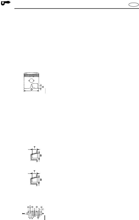
|
|
|
|
|
|
SPEC |
|
|
MAINTENANCE SPECIFICATIONS |
|
|
|
|
|
MAINTENANCE SPECIFICATIONS
ENGINE
E
Item |
|
|
|
Unit |
|
Model |
|||||
|
|
|
40 hp |
|
50 hp |
||||||
|
|
|
|
|
|
|
|
|
|
||
|
|
|
|
|
|
|
|
|
|
|
|
CYLINDER HEAD: |
|
|
|
|
|
|
|
||||
Warpage limit |
|
|
|
mm (in) |
|
0.1 (0.004) |
|||||
|
|
|
|
|
|
|
|
|
|
|
|
CYLINDER: |
|
|
|
|
|
|
|
||||
Bore size |
|
|
|
mm (in) |
67.00 ~ 67.02 (2.638 ~ 2.639) |
||||||
Wear limit |
|
|
|
mm (in) |
|
67.10 (2.642) |
|||||
Taper limi |
|
|
|
mm (in) |
|
0.08 (0.003) |
|||||
Out of round limit |
|
|
|
mm (in) |
|
0.05 (0.002) |
|||||
|
|
|
|
|
|
|
|
|
|
|
|
PISTON: |
|
|
|
|
|
|
|
|
|
|
|
|
|
|
|
|
|
|
|
|
|
||
Identification mark |
|
|
|
|
|
|
mm (in) |
|
W |
||
Piston clearance |
|
|
|
|
|
|
mm (in) |
0.060 ~ 0.065 (0.0024 ~ 0.0026) |
|||
Limit |
|
|
|
|
|
|
mm (in) |
|
0.115 (0.0045) |
||
Diameter D |
|
|
|
|
|
|
mm (in) |
66.940 ~ 67.000 (2.6354 ~ 2.6378) |
|||
Measuring point H |
|
|
|
|
|
|
mm (in) |
|
10 (0.4) |
||
Pin boss inside diameter |
|
|
|
mm (in) |
18.008 ~ 18.015 (0.7090 ~ 0.7093) |
||||||
Ring groove clearance (installed) |
mm (in) |
|
|
|
|||||||
|
|
|
|
|
top |
mm (in) |
0.04 ~ 0.08 (0.002 ~ 0.003) |
||||
|
|
|
|
|
2nd |
mm (in) |
0.03 ~ 0.07 (0.001 ~ 0.003) |
||||
Over size piston |
|
|
|
mm (in) |
|
|
|
||||
Diameter |
1st*1 |
mm (in) |
|
67.25 (2.648) |
|||||||
|
|
|
|
|
2nd |
mm (in) |
|
67.50 (2.657) |
|||
|
|
|
|
|
|
|
|
|
|
|
|
PISTON PIN: |
|
|
|
|
|
|
|
||||
Diameter |
|
|
|
mm (in) |
17.995 ~ 18.000 (0.7085 ~ 0.7087) |
||||||
|
|
|
|
|
|
|
|
|
|
|
|
PISTON RING (1st): |
|
|
|
|
|
|
|
||||
Type |
|
|
|
|
|
mm (in) |
|
Keystone |
|||
Dimensions (B × T) |
|
|
|
|
|
mm (in) |
2.0 × 2.6 (0.08 × 0.10) |
||||
End gap (installed) |
|
|
|
|
|
mm (in) |
0.40 ~ 0.60 (0.016 ~ 0.024) |
||||
Limit |
|
|
|
|
|
mm (in) |
|
0.80 (0.031) |
|||
|
|
|
|
|
|
||||||
|
|
|
|
|
|
|
|
|
|
|
|
PISTON RING (2nd): |
|
|
|
|
|
|
|
|
|||
|
|
|
|
|
|
|
|
||||
Type |
|
|
|
|
mm (in) |
|
Keystone |
||||
Dimensions (B × T) |
|
|
|
|
mm (in) |
2.0 × 2.6 (0.08 × 0.10) |
|||||
End gap (installed) |
|
|
|
|
mm (in) |
0.40 ~ 0.60 (0.016 ~ 0.024) |
|||||
Limit |
|
|
|
|
mm (in) |
|
0.80 (0.031) |
||||
|
|
|
|
|
|||||||
|
|
|
|
|
|
|
|
|
|
|
|
CONNECTING ROD: |
|
|
|
|
|
|
|
||||
Small end diameter |
|
|
|
mm (in) |
22.005 ~ 22.008 (0.8663 ~ 0.8665) |
||||||
|
|
|
|
|
|
|
|
|
|
|
|
CRANK SHAFT ASSEMBLY: |
|
|
|
|
|
|
|
||||
Crank width A |
|
|
|
|
mm (in) |
53.90 ~ 53.95 (2.122 ~ 2.124) |
|||||
Crank width B |
|
|
|
|
mm (in) |
32.88 ~ 33.10 (1.294 ~ 1.303) |
|||||
Runout limit D |
|
|
|
|
mm (in) |
|
0.03 (0.001) |
||||
|
|
|
|
|
|
|
|||||
Big end side clearance E |
|
|
|
mm (in) |
0.20 ~ 0.70 (0.008 ~ 0.028) |
||||||
Small end axial play limit F |
|
|
|
mm (in) |
|
2.0 (0.08) |
|||||
|
|
|
|
|
|
|
|
|
|
|
|
*1: Except for U.S.A.
2-7

SPEC 


MAINTENANCE SPECIFICATIONS |
E |
Item |
|
Unit |
|
|
Model |
|
|
|
40 hp |
50 hp |
|||||
|
|
|
|||||
|
|
|
|
|
|
|
|
THERMOSTAT: |
|
|
|
|
|
|
|
Opening temperature |
|
˚C (˚F) |
|
48 ~ 52 (118 ~ 126) |
|
||
Full-opening temperature |
|
˚C (˚F) |
|
60 (140) |
|
||
Valve lift |
|
mm (in) |
|
3 (0.12) |
|
||
|
|
|
|
|
|
|
|
OIL INJECTION PUMP: |
|
|
|
|
|
|
|
Identification mark |
|
|
|
|
63D00 |
|
|
Specified discharge |
|
cm3 (US |
1.60 ± 0.50 (0.054 ± 0.017, 0.056 ± 0.018) |
||||
|
|
oz, Imp oz) |
|||||
|
|
|
|
|
|
|
|
REED VALVE: |
|
|
|
|
|
|
|
Valve stopper height |
|
mm (in) |
|
6.0 ± 0.2 (0.24 ± 0.01) |
|
||
Valve bending limit |
|
mm (in) |
|
0.2 (0.01) |
|
||
|
|
|
|
|
|
|
|
CARBURETOR: |
|
|
(M model) |
|
(E, W model) |
(M model) |
(E, W model) |
Identification mark |
|
|
63B00 |
|
63D00 |
62W00 |
62X00 |
Float height |
|
mm (in) |
|
|
|
|
|
|
|
|
15.0 ± 1.0 |
(0.59 ± 0.04) |
|
||
Valve seat size |
|
mm (in) |
|
1.2 (0.05) |
|
||
Main jet |
(M.J.) |
# |
|
|
|
||
115 118(M) |
125 |
130 |
|||||
Main nozzle |
(M.N.) |
mm (in) |
3.0 (0.12) |
3.2 (0.13) |
3.0 (0.12) |
||
Main air jet |
(M.A.J.) |
# |
|
160 |
130 |
140 |
|
Pilot jet |
(P.J.) |
# |
|
60 |
|
|
|
|
62 |
||||||
Pilot air jet |
(P.A.J.) |
# |
|
75 |
|
|
|
|
90 |
80 |
|||||
Pilot screw |
(P.S.) |
turns out |
1-1/2 ± 1/4 |
1-5/8 ± 1/4 |
1-3/8 ± 1/4 |
||
Starter jet |
(S.J.) |
mm (in) |
|
|
— |
1.0 (0.04) |
|
— |
|
1.0 (0.04) |
|||||
Electrothermal valve resistance |
Ω (color) |
— |
|
2.32 ~ 3.48 |
— |
2.32 ~ 3.48 |
|
(color — color) |
|
|
(L — B) |
(L — B) |
|||
|
|
|
|
|
|||
Idle speed |
|
rpm |
|
|
|
|
|
|
|
|
800 |
± 50 |
|
||
RECOIL STARTER: |
|
|
|
|
|
|
|
Starter rope length |
|
mm (in) |
|
2,095 (82.5) |
|
||
|
|
|
|
|
|
|
|
2-8

|
|
|
|
|
|
|
|
|
|
SPEC |
|
|
MAINTENANCE SPECIFICATIONS |
|
E |
||
|
|
|
|
|
|
|
|
|
|
LOWER |
|
|
|
|
|
||
|
|
|
|
|
|
|
|
|
|
|
Item |
Unit |
|
Model |
|||
|
|
40 hp |
|
50 hp |
||||
|
|
|
|
|
|
|
||
|
|
|
|
|
|
|
||
|
GEAR BACKLASH: |
|
|
|
|
|
||
|
Pinion - forward |
|
mm (in) |
0.18 ~ 0.45 (0.007 ~ 0.018) |
||||
|
Pinion - reverse |
|
mm (in) |
0.71 ~ 0.98 (0.028 ~ 0.039) |
||||
|
Pinion shims |
|
mm (in) |
0.05, 0.08, 0.12, 0.30, 0.50 |
||||
|
Forward shims |
|
mm (in) |
0.05, 0.08, 0.12, 0.30, 0.50 |
||||
|
Reverse shims |
|
mm (in) |
0.05, 0.08, 0.12, 0.30, 0.50 |
||||
|
|
|
|
|
|
|
||
|
PROPELLER: |
|
|
|
|
|
||
|
Material |
|
|
Aluminum |
|
Stainless steel |
||
|
No. of blades × diameter × pitch |
in |
3 × 10 × 15 |
3 × 10⁻¹/4 × 14 |
||||
|
|
|
|
|
|
3 × 10⁻¹/4 × 14 |
3 × 10⁻¹/4 × 15 |
|
|
|
|
|
|
|
3 × 10⁻³/4 × 16 |
3 × 10⁻¹/4 × 16 |
|
|
|
|
|
|
|
3 × 10⁻³/4 × 17 |
3 × 10⁻⁵/8 × 13 |
|
|
|
|
|
|
|
3 × 10⁻³/8 × 13 |
3 × 11-1/4 × 14 |
|
|
|
|
|
|
|
3 × 10⁻⁵/8 × 12 |
3 × 11-1/2 × 13 |
|
|
|
|
|
|
|
3 × 11-1/8 × 13 |
3 × 12 × 11 |
|
|
|
|
|
|
|
3 × 11-1/4 × 14 |
3 × 12 × 12 |
|
|
|
|
|
|
|
3 × 11-3/8 × 12 |
|
|
|
|
|
|
|
|
3 × 11-5/8 × 11 |
|
|
|
|
|
|
|
|
3 × 11-3/4 × 10 |
|
|
|
|
|
|
|
|
3 × 12-1/4 × 9 |
|
|
|
Test propeller 1 |
|
|
90890-01611 |
|
90890-01611 |
||
|
rpm |
|
r/min |
4,900 ~ 5,100 |
|
5,250 ~ 5,450 |
||
|
Test propeller 2 |
|
|
YB-1611 |
|
YB-1611 |
||
|
rpm |
|
r/min |
4,900 ~ 5,100 |
|
5,250 ~ 5,450 |
||
|
|
|
|
|
|
|||
|
POWER TRIM AND TILT: |
|
|
|
|
|||
|
Fluid type |
|
|
ATF (Dexiron2) |
||||
|
Fluid capacity |
|
cm3 (US |
434 (14.7, 15.3) |
||||
|
|
|
|
|
oz, Imp oz) |
|
|
|
|
Brush length |
|
mm (in) |
10 (0.39) |
||||
|
Wear limit |
|
mm (in) |
3.5 (0.14) |
||||
|
Commutator diameter |
mm (in) |
22 (0.87) |
|||||
|
Limit |
|
mm (in) |
21 (0.83) |
||||
|
Commutator under cut |
mm (in) |
1.5 (0.06) |
|||||
|
|
|
|
|
|
|
|
|
2-9
 Loading...