


15C
Table of contents
 Loading...
OWNER’S MANUAL
9.9C
15C
U.S.A.Edition
LIT-18626-05-34

EMU01448
TO THE OWNER
Thank you for choosing a Yamaha outboard motor. This Owner’s manual contains information needed for proper operation, maintenance and care. A thorough
understanding of these simple instructions will help you obtain maximum
enjoyment from your new Yamaha. If you
have any question about the operation or
maintenance of your outboard motor,
please consult a Yamaha dealer.
In this Owner’s Manual particularly
important information is distinguished in
the following ways.
The Safety Alert Symbol means
ATTENTION! BECOME ALERT!
Q
YOUR SAFETY IS INVOLVED!
E
cC
A CAUTION indicates special precautions
that must be taken to avoid damage to
the outboard motor.
NOTE:
A NOTE provides key information to make
procedures easier or clearer.
* Yamaha continually seeks advance-
ments in product design and quality.
Therefore, while this manual contains
the most current product information
available at the time of printing, there
may be minor discrepancies between
your machine and this manual. If there
is any question concerning this manual,
please consult your Yamaha dealer.
w
Failure to follow WARNING instructions
could result in severe injury or death to
the machine operator, a bystander, or a
person inspecting or repairing the outboard motor.
EMU01446
9.9C, 15C
OWNER'S MANUAL
©2003 by Yamaha Motor Corporation, USA
1st Edition, March 2003
All rights reserved.
Any reprinting or unauthorized use
without the written permission of
Yamaha Motor Corporation, USA
is expressly prohibited.
Printed in Japan
P/N LIT-18626-05-34
NOTE:
The 15MH and its standard accessories
are used as a base for the explanations
and illustrations in this manual. Therefore, some items may not apply to every
model.
CONTENTS
E
GENERAL INFORMATION
BASIC COMPONENTS
OPERATION
MAINTENANCE
1
2
3
4
TROUBLE RECOVERY
INDEX
READ THIS OWNER’S MANUAL CAREFULLY
BEFORE OPERATING YOUR OUTBOARD MOTOR.
5
6
E
EMB00010
Chapter 1
GENERAL
INFORMATION
IDENTIFICATION NUMBERS
RECORD ....................................................1-1
Outboard motor serial number...........1-1
EMISSION CONTROL INFORMATION...1-2
SAFETY INFORMATION..........................1-3
1
2
IMPORTANT LABELS ..............................1-5
BASIC BOATING RULES .........................1-6
FUELING INSTRUCTIONS.....................1-10
Gasoline ..............................................1-11
Engine oil ............................................1-11
PROPELLER SELECTION .......................1-12
START-IN-GEAR PROTECTION ............1-13
3
4
5
6
1
401012
E
E
EMU00005
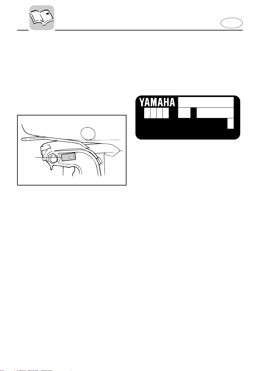
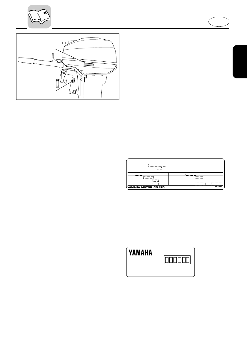
IDENTIFICATION NUMBERS
RECORD
EMU00007
OUTBOARD MOTOR SERIAL
NUMBER
YAMAHA MOTOR CO., LTD.
MADE IN JAPAN
PAYS D'ORIGINE JAPON
The outboard motor serial number is
stamped on the label attached to the port
side of the clamp-bracket.
Record your outboard motor serial number in the spaces provided to assist you in
ordering spare parts from your Yamaha
dealer or for reference in case your outboard motor is stolen.
1 Outboard motor serial number
1-1
E
q
w
108015*
EMISSION CONTROL INFORMATION
ENGINE FAMILY :
THIS ENGINE CONFORMS TO 2001 U.S. EPA REGULATIONS FOR MARINE SI ENGINES.
REFER TO THE OWNERS MANUAL FOR MAINTENANCE SPECIFICATIONS AND ADJUSTMENTS.
FELs :
SPARK PLUG :
DISPLACEMENT :
ADVERTISED POWER :
IDLE SPEED :
SPARK PLUG GAP (mm) :
FUEL : GASOLINE
VALVE LASH (mm) :
IN EX
cm
kw
g/kw-hr
rpm IN NEUTRAL
3
Manufactured:
EMU01385
EMISSION CONTROL
INFORMATION
EMU01386
NORTH AMERICAN MODELS
This engine conforms to U.S. Environmental Protection Agency (EPA) regulations for marine SI engines. See the label
affixed to your engine for details.
Approval label of Emission control
certificate
This label is attached to the bottom cowling.
1 Emission control information label
Existing Technology ; N/A
Manufactured date label
This label is attached to the clamp bracket
or the swivel bracket.
2 Manufactured date label
1-2

E
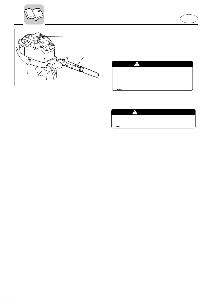
EMU00917
Q
8 Before mounting or operating the out-
board motor, read this entire manual.
Reading it should give you an understanding of the motor and its operation.
8 Before operating the boat, read any
owner’s or operator’s manuals supplied
with it and all labels. Be sure you understand each item before operating.
8 Do not overpower the boat with this
outboard motor. Overpowering the
boat could result in loss of control. The
rated power of the outboard should be
equal to or less than the rated horsepower capacity of the boat. If the rated
horsepower capacity of the boat is
unknown, consult the dealer or boat
manufacturer.
8 Do not modify the outboard. Modifica-
tions could make the motor unfit or
unsafe to use.
8 Never operate after drinking alcohol or
taking drugs. About 50% of all boating
fatalities involve intoxication.
8 Have an approved personal flotation
device (PFD) on board for every occupant. It is a good idea to wear a PFD
whenever boating. At a minimum, children and non-swimmers should always
wear PFDs, and everyone should wear
PFDs when there are potentially hazardous boating conditions.
8 Gasoline is highly flammable, and its
vapors are flammable and explosive.
Handle and store gasoline carefully.
Make sure there are no gas fumes or
leaking fuel before starting the engine.
SAFETY
INFORMATION
8 This product emits exhaust gases which
contain carbon monoxide, a colorless,
odorless gas which may cause brain
damage or death when inhaled. Symptoms include nausea, dizziness, and
drowsiness. Keep cockpit and cabin
areas well ventilated. Avoid blocking
exhaust outlets.
8 Check throttle, shift, and steering for
proper operation before starting the
engine.
8 Attach the engine stop switch lanyard
to a secure place on your clothing, or
your arm or leg while operating. If you
accidentally leave the helm, the lanyard
will pull from the switch, stopping the
engine.
8 Know the marine laws and regulations
where you will be boating - and obey
them. Refer to the “RULES OF THE
ROAD” section for basic boating rules.
8 Stay informed about the weather.
Check weather forecasts before boating.
Avoid boating in hazardous weather.
8 Tell someone where you are going:
leave a Float Plan with a responsible
person. Be sure to cancel the Float Plan
when you return.
8 Use common sense and good judgment
when boating. Know your abilities, and
be sure you understand how your boat
handles under the different boating
conditions you may encounter. Operate
within your limits, and the limits of your
boat. Always operate at safe speeds,
and keep a careful watch for obstacles
and other traffic.
8 Always watch carefully for swimmers
during the engine operation.
8 Stay away from swimming areas.
8 When a swimmer is in the water near
you shift into neutral and shut off the
engine.
1-3

8 Be informed about boating safety. Addi-
tional publications and information can
be obtained from many organizations,
including the following:
United States Coast Guard
Consumer Affairs Staff (G-BC)
Office of Boating, Public, and Consumer
Affairs
U.S. Coast Guard Headquarters
Washington, D.C. 20593-0001
Boating Safety Hotline: 1-800-368-5647
National Marine Manufacturers
Association (NMMA)
401 N. Michigan Ave.
Chicago, Il 60611
Marine Retailers Association of America
155 N. Michigan Ave.
Chicago, Il 60601
E
1-4
EMB30010
202012*
q
w
WARNING
●Be sure shift control is in neutral
before starting engine. (except 2HP)
●Do not touch or remove electrical parts
when starting or during operation.
●Keep hands,hair,and clothes away from flywheel
and other rotating parts while engine is running.
6A1-83625-41
IMPORTANT LABELS
WARNING LABELS
1
2
This engine is equipped with a neutral starting device.
The engine will not start unless the shift control is
in neutral position.
WARNING
E
6E0-83627-41
1-5

EMB40010
BASIC BOATING RULES
(Rules of the road)
Just as there are rules which apply when
you are driving on streets and high ways,
there are waterway rules which apply
when you are driving your boat. These
rules are used internationally, and are
also enforced by the United States Coast
Guard and local agencies. You should be
aware of these rules, and follow them
whenever you encounter another vessel
on the water.
Several sets of rules prevail according to
geographic location, but are all basically
the same as the International Rules of the
Road. The rules presented here in your
Owner’s Manual are condensed, and have
been provided for your convenience only.
Consult your local U.S. Coast Guard Auxiliary or Department of Motor Vehicles for
a complete set of rules governing the
waters in which you will be using your
boat.
STEERING AND SAILING RULES AND
SOUND SIGNALS
Whenever two vessels on the water meet
one another, one vessel has the right-ofway; it is called the “stand-on” vessel.
The vessel which does not have the rightof-way is called the “give-way” or “bur-
dened” vessel. These rules determine
which vessel has the right-of-way, and
what each vessel should do.
E
Stand-on Vessel
The vessel with the right-of-way has the
duty to continue its course and speed,
except to avoid an immediate collision.
When you maintain your direction and
speed, the other vessel will be able to
determine how best to avoid you.
Give-way Vessel
The vessel which does not have the rightof-way has the duty to take positive and
timely action to stay out of the way of the
Stand-On vessel. Normally, you should
not cross in front of the vessel with the
right-of-way. You should slow down or
change directions briefly and pass behind
the other vessel. You should always move
in such a way that the operator of the
other vessel can see what you are doing.
“The general prudential rule”
This rule is called Rule 2 in the International Rules and says,
‘In obeying and construing these
rules due regard shall be had to all
dangers of navigation and collision,
and to any special circumstances,
which may render a departure from
the above rules necessary in order to
avoid immediate danger.’
In other words, follow the standard rules
except when a collision will occur unless
both vessels try to avoid each other. If
that is the case, both vessels become
“Give-Way” vessels.
1-6
E
102045
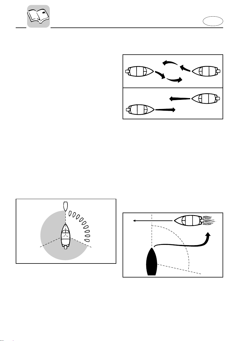
RULES WHEN ENCOUNTERING
VESSELS
There are three main situations which you
may encounter with other vessels which
could lead to a collision unless the Steering Rules are followed:
Meeting
(you are approaching another vessel
head-on)
Crossing
(you are travelling across the other
vessel’s path)
Overtaking
(you are passing or being passed by
another vessel)
In the following illustration, your boat is
in the center. You should give the right-ofway to any vessels shown in white area
(you are the Give-Way vessel). Any vessels in the shaded area must yield to you
(they are the Give-Way vessels). Both you
and the meeting vessel must alter course
to avoid each other.
side. This rule doesn’t apply if both of you
will clear one another if you continue on
your set course and speed.
102044
Crossing
When two power driven vessels are
crossing each other’s path close enough
to run the risk of collision, the vessel
which has the other on the starboard
(right) side must keep out of the way of
the other. If the other vessel is on your
right, you must keep out of its way; you
are the Give-Way vessel. If the other vessel is on your port (left) side, remember
that you should maintain course and
direction, provided the other vessel gives
you the right-of-way as it should.
Meeting
If you are meeting another power vessel
head on, and are close enough to run the
risk of collision, neither of you has the
right-of-way! Both of you should alter
course to avoid an accident. You should
keep the other vessel on your port (left)
102046
Overtaking
If you are passing another vessel, you are
the “Give-Way” vessel. This means that
the other vessel is expected to maintain
its course and speed. You must stay out
1-7

E
of its way until you are clear of it. Likewise, if another vessel is passing you, you
should maintain your speed and direction
so that the other vessel can steer itself
around you.
OTHER SPECIAL SITUATIONS
There are three other rules you should be
aware of when driving your boat around
other vessels.
Narrow Channels and Bends
When navigating in narrow channels, you
should keep to the right when it is safe
and practical to do so. If the operator of a
power-driven vessel is preparing to go
around a bend that may obstruct the view
of other water vessels, the operator
should sound a prolonged blast on the
whistle (4 to 6 seconds). If another vessel
is around the bend, it too should sound
the whistle. Even if no reply is heard,
however, the vessel should still proceed
around the bend with caution. If you navigate such waters with your boat, you will
need to carry a portable air horn, available from local marine supply stores.
Fishing Vessel Right-of-way
All vessels which are fishing with nets,
lines or trawls are considered to be“fish-
ing vessels” under the International
Rules. Vessels with trolling lines are not
considered fishing vessels. Fishing vessels have the right-of-way regardless of
position. Fishing vessels cannot, however, impede the passage of other vessels in
narrow channels.
Sailing Vessel Right-of-way
Sailing vessels should normally be given
the right-of-way. The exceptions to this
are:
1. When the sailing vessel is overtaking
the power-driven vessel, the powerdriven vessel has the right-of-way.
2. Sailing vessels should keep clear of
any fishing vessel.
3. In a narrow channel, a sailing vessel
should not hamper the safe passage
of a power-driven vessel which can
navigate only in such a channel.
Reading Buoys and Other Markers
The waters of the United states are
marked for safe navigation by the lateral
system of buoyage. Simply put, buoys
and markers have an arrangement of
shapes, colors, numbers and lights to
show which side of the buoy a boater
should pass on when navigating in a particular direction. The markings on these
buoys are oriented from the perspective
of being entered from seaward (the
boater is going towards the port). This
means that red buoys are passed on the
starboard (right) side when proceeding
from open water into port, and black
buoys are to port (left) side. When navigating out of port, your position with
respect to the buoys should be reversed;
red buoys should be to port and black
buoys to starboard.
Many bodies of water used by boaters are
entirely within the boundaries of a particular state. The Uniform State Waterway
Marking System has been devised for
these waters. This system uses buoys and
signs with distinctive shapes and colors
to show regulatory or advisory information. These markers are white with black
letters and orange boarders. They signify
speed zones, restricted areas, danger
areas, and general information.
1-8
Remember, markings may vary by geo-
1
1
A
1
1
Proceeding toward head
of navigation from seaward
CAN BUOY
Odd number. Leave to port.
OR
SECONDARY CHANNEL BUOYS
STARTS NEW NUMBERING SYSTEM
old new
C " 1
"
NUN BUOY
Even number. Leave to starboard
N
"
2
"
No change
BUOY
COLOR CODE
BLACK
RED
GREEN
"
A
"
"
2
"
"
1
"
"
3
"
"
4
"
"
5
"
"
7
"
N
"
2
"
"
6
"
C
"
1
"
RB
"
L
"
RG
"
L
"
or
SECONDARY CHANNEL
MAIN CHANNEL
old
new
2
2
2
A
L
L
Odd number. increasing toward head of naviga-
MAIN CHANNEL BUOYS
"
1
" "
3
" "
5
" "
7
"
tion.Leave to port (left) proceeding upstream.
LIGHTED BUOY (Port Hand)`
White Light
Green Light
old
new
old
new
old
new
LIGHTED BUOY (Starboard Hand)`
"
2
" "
4
" "
6
"
Even number,increasing toward head of navigation. Leave to starboard (right) proceeding upstream.
White Light Red Light
"
A
"
LIGHTED SAFE WATER BUOY
No number. Marks midchannel, pass on either
side. Letter has no lateral significance, used for
No number. Topmost band red
-
preferred
Top Mark
White Light
White Light
OR
OR
LIGHTED PREFERRED CHANNEL TO
RB
"
L
"
RG
"
L
"
PORT BUOY
identification and location purposes.
channel is to left of buoy. Letter has no lateral
significance, used for identification and location
purposes.
Red Light
Red or
White Light
OR
102052
graphic location. Always consult local
boating authorities before driving your
boat in unfamiliar waters.
E
1-9

E
EMU00016
FUELING INSTRUCTIONS
w
GASOLINE AND ITS VAPORS ARE HIGHLY FLAMMABLE AND EXPLOSIVE!
8 Do not smoke when refueling, and
keep away from sparks, flames, or
other sources of ignition.
8 Stop engine before refueling.
8 Refuel in a well-ventilated area. Refuel
portable fuel tanks off the boat.
8 Take care not to spill gasoline. If gaso-
line spills, wipe it up immediately with
dry rags.
8 Do not overfill the fuel tank.
8 Tighten the filler cap securely after
refueling.
8 If you should swallow some gasoline
inhale a lot of gasoline vapor, or get
gasoline in your eyes, get immediate
medical attention.
8 If any gasoline spills onto your skin,
immediately wash with soap and
water. Change clothing if gasoline spills
on it.
8 Touch the fuel nozzle to the filler open-
ing or funnel to help prevent electrostatic sparks.
cC
Use only new clean gasoline which has
been stored in clean containers and is not
contaminated with water or foreign matter.
1-10
E
EMU01804
GASOLINE
Recommended gasoline:
Regular unleaded gasoline with a
minimum octane rating of 86
(Pump Octane Number) = (R+M)/2
If knocking or pinging occurs, use a different brand of gasoline or premium unleaded fuel.
EMU00027
Gasohol
There are two types of gasohol: gasohol
containing ethanol and that containing
methanol. Gasohol containing ethanol
can be used if ethanol content does not
exceed 10% and the fuel meets minimum
octane ratings. Gasohol containing
methanol is not recommended by Yamaha because it can cause fuel system damage or engine performance problems.
EMU00858
ENGINE OIL
Recommended oil:
YAMALUBE 2 STROKE OUTBOARD OIL
If the recommended engine oil is not
available, another 2-stroke engine oil with
a NMMA-certified TC-W3 rating may be
used.
1-11

E
EMU01395
PROPELLER SELECTION
The performance of your outboard motor
will be critically affected by your choice of
propeller, as an incorrect choice could
adversely affect performance and could
also seriously damage the motor. Engine
speed depends on the propeller size and
boat load. If engine speed is too high or
too low for good engine performance,
this will have an adverse effect on the
engine.
Yamaha outboard motors are fitted with
propellers chosen to perform well over a
range of applications, but there may be
uses where a propeller with a different
pitch would be more appropriate. For a
greater operating load, a smaller-pitch
propeller is more suitable as it enables
the correct engine speed to be maintained. Conversely, a larger-pitch propeller is more suitable for a smaller operating load.
Yamaha dealers stock a range of propellers, and can advise you and install a
propeller on your outboard that is best
suited to your application.
1-12
E
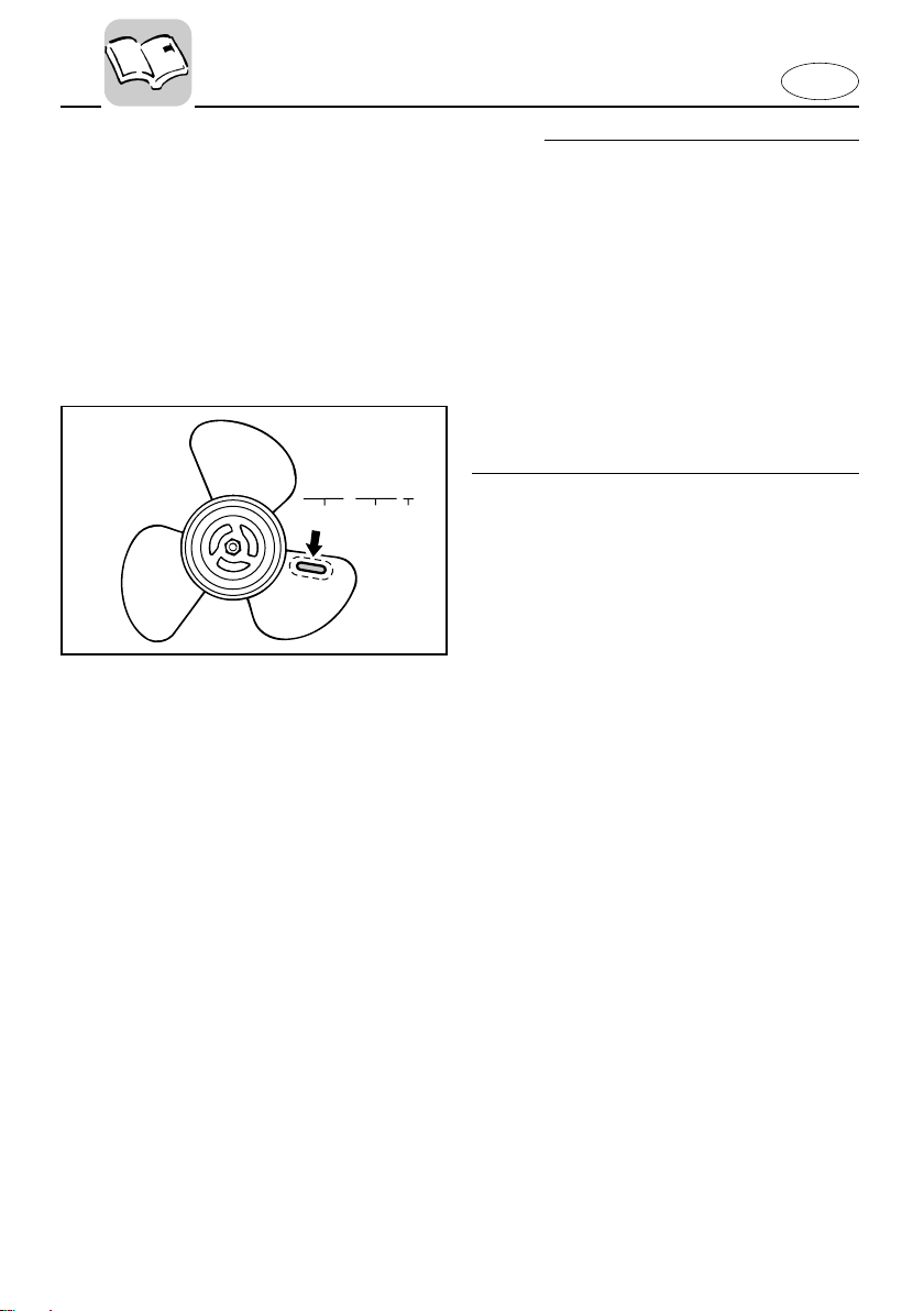
9-1/4x9-3/4-J
1
23
602021
NOTE:
At full throttle and under a maximum
boat load, the engine’s rpm should be
within the upper half of the full throttle
operating range, as listed in “SPECIFICA-
TIONS” on page 4-1. Select a propeller
which fulfills this requirement.
If operating under conditions which allow
the engine’s rpm to rise above the maximum recommended range (such as light
boat loads), reduce the throttle setting to
maintain the rpm in the proper operating
range.
1 Propeller diameter (in inches)
2 Propeller pitch (in inches)
3 Type of propeller (propeller mark)
Refer to the section “CHECKING PROPELLER” for instructions on propeller
removal and installation.
EMU01209
START-IN-GEAR PROTECTION
Yamaha outboard motors or Yamaha
approved remote control units are
equipped with start-in-gear protection
device(s). This feature permits the engine
to be started only when it is Neutral.
Always select Neutral before starting the
engine.
1-13
E
EMC00010
Chapter 2
BASIC COMPONENTS
MAIN COMPONENTS..............................2-1
OPERATIONS OF CONTROLS AND
OTHER FUNCTIONS ................................2-2
Fuel tank ................................................2-2
Gear shift lever .....................................2-2
Engine stop button...............................2-3
Engine stop lanyard switch .................2-3
Throttle control grip .............................2-4
Choke knob ...........................................2-4
Recoil starter handle ............................2-4
Tiller handle ..........................................2-5
Steering friction adjustment ...............2-6
Trim angle adjusting rod .....................2-6
Tilt lock mechanism .............................2-6
Tilt support bar .....................................2-7
Top cowling lock lever.........................2-7
Carrying handle ....................................2-7
1
2
3
4
5
6
101022*
902063
902051*
!9
!8
101232
!2
!1
!3
!5
!4
!6
u
o
y
i
!0
t
!7
q
w
e
r
EMU01206
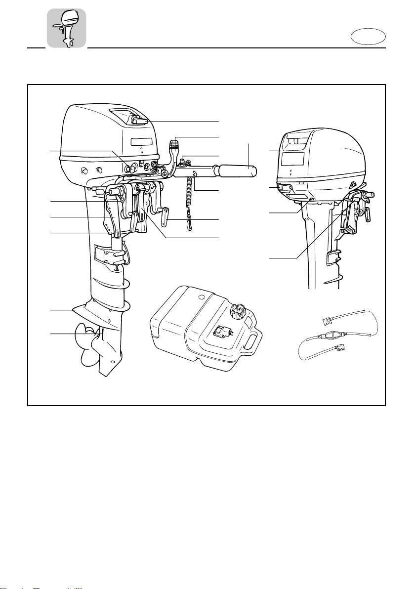
MAIN COMPONENTS
E
1 Top cowling
2 Cowling lock lever
3 Cooling water pilot hole
4 Tilt lock lever
5 Recoil starter handle
6 Gear shift lever
7 Throttle control grip
8 Throttle friction adjustment knob
9 Engine stop button/
Engine stop lanyard switch
0 Clamp screw
2-1
q Carrying handle
w Cooling water inlet
e Anti-cavitation plate
r Trim angle adjusting rod
t Clamp bracket
y Rope attachment
u Choke knob
i Fuel tank
o Fuel hose
* May not be exactly as shown; also may not
be included as standard equipment on all
models.
q
406041
1
3
2
e
r
w
E
EMC20010
OPERATIONS OF CONTROLS
AND OTHER FUNCTIONS
EMC21012
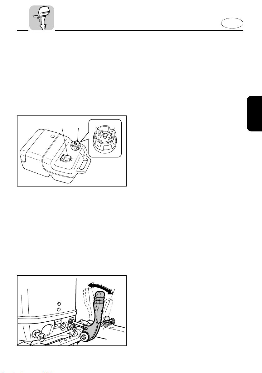
FUEL TANK
If your model was equipped with a
portable fuel tank, its function is as follows.
1 Fuel hose joint
2 Fuel meter(If equipped)
3 Fuel tank cap
4 Air vent screw(If equipped)
Fuel hose joint
This connector is provided for connecting
or disconnecting fuel hose.
902051
Fuel meter
This meter is on the fuel tank cap. It
shows current fuel quantity in the fuel
tank approximately.
Fuel tank cap
This cap is for filling fuel. To remove it,
turn it counterclockwise.
Air Vent screw
This screw is on the fuel tank cap. To
loosen it, turn it counterclockwise.
EMC25010
GEAR SHIFT LEVER
(for Tiller control model):
Turning the gear-shift lever towards you
engages the clutch with the forward gear
so that the boat moves ahead. Turning
the lever away from you engages the
reverse gear so that the boat moves
astern.
1 Neutral
2 Forward
3 Reverse
2-2
407021*
q
w
407021
E
EMC27011
ENGINE STOP BUTTON (for Tiller
control model)
Pushing this button opens the ignition circuit and stops the engine.
EMU00931
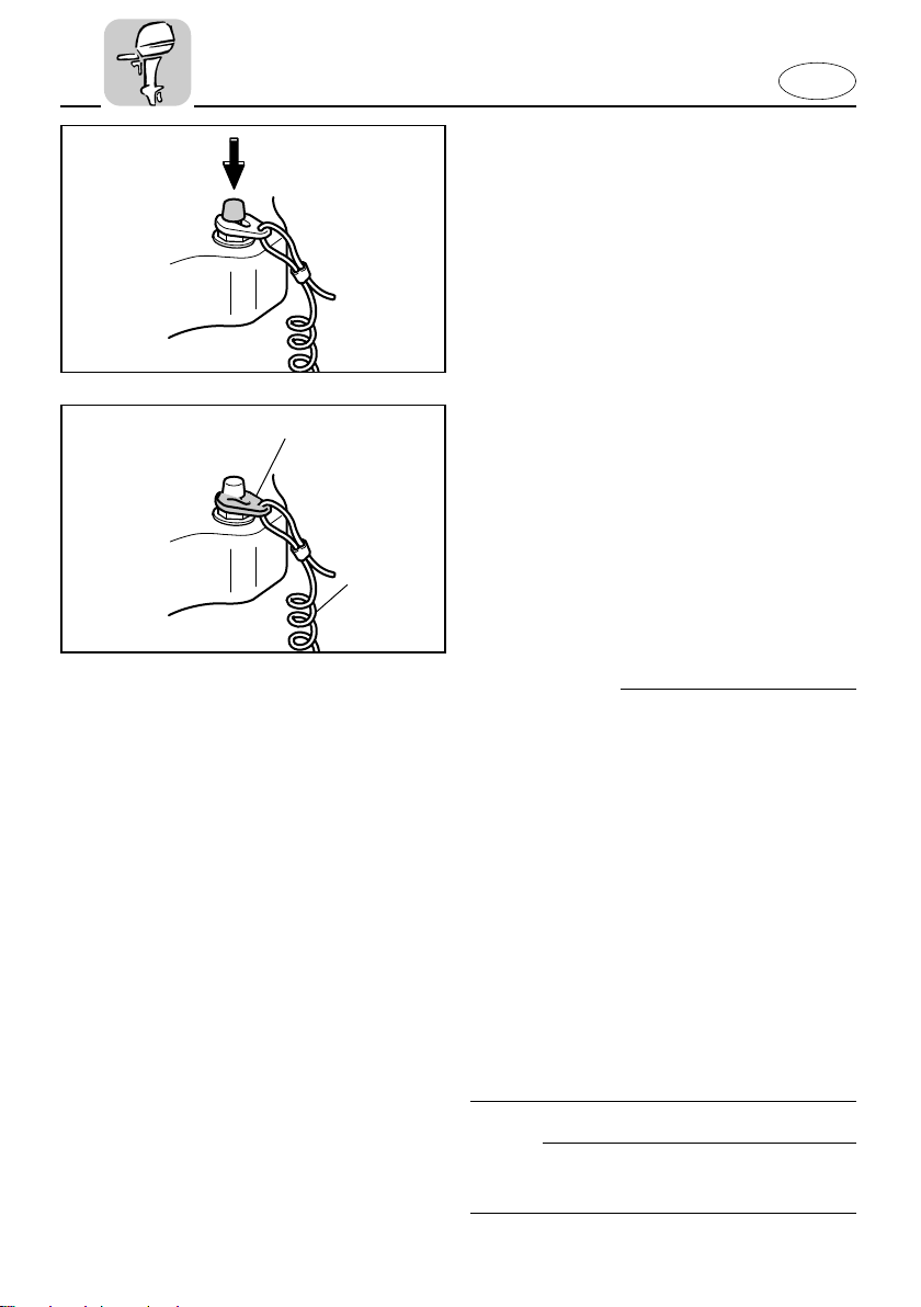
ENGINE STOP LANYARD SWITCH
(for Tiller control model)
The lock-plate 1 must be attached to the
engine stop lanyard switch for the engine
to run. The lanyard 2 should be attached
to a secure place on the operator’s clothing, or arm or leg. Should the operator fall
overboard or leave the helm, the lanyard
will pull out the lock plate, stopping ignition to the engine. This will prevent the
boat from running away under power.
w
8 Attach the lanyard to a secure place on
your clothing, your arm or leg while
operating.
8 Do not attach the lanyard to clothing
that could tear loose. Do not route the
lanyard in such a way that it could
become entangled, preventing it from
functioning.
8 Avoid accidentally pulling the lanyard
during normal operation. Loss of
engine power means the loss of most
steering control. Also, without engine
power, the boat could slow rapidly.
This could cause people and objects in
the boat to be thrown forward.
NOTE:
The engine cannot be started with the
lock-plate removed.
2-3
E
503013
q
305071
1
2
3
4
EMC40010
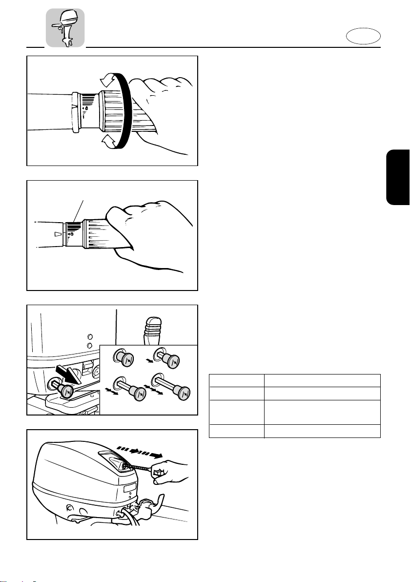
THROTTLE CONTROL GRIP
(for Tiller control model)
The throttle control grip is on the tiller
handle. Turn the grip counterclockwise to
increase speed and clockwise to decrease
speed.
Throttle indicator
The fuel consumption curve on the throttle indicator shows the relative amount of
fuel consumed for each throttle position.
Choose the setting that offers the best
performance and fuel economy for the
desired operation.
1 Throttle indicator
EMC42310
CHOKE KNOB
Pulling out this knob supplies a rich mixture required to start or warm up the
engine. There are 4 operating position as
shown below :
Position Function
1 To start a hot engine
2 or 3 To warm up a cold engine
or restart a warm engine
4 To start a cold engine
EMC44010
RECOIL STARTER HANDLE
(If equipped)
Pull the handle gently until resistance is
felt. Then vigorously pull the handle
209011
straight out to crank the engine to start it.
2-4
503015
502011
E
EMC60010
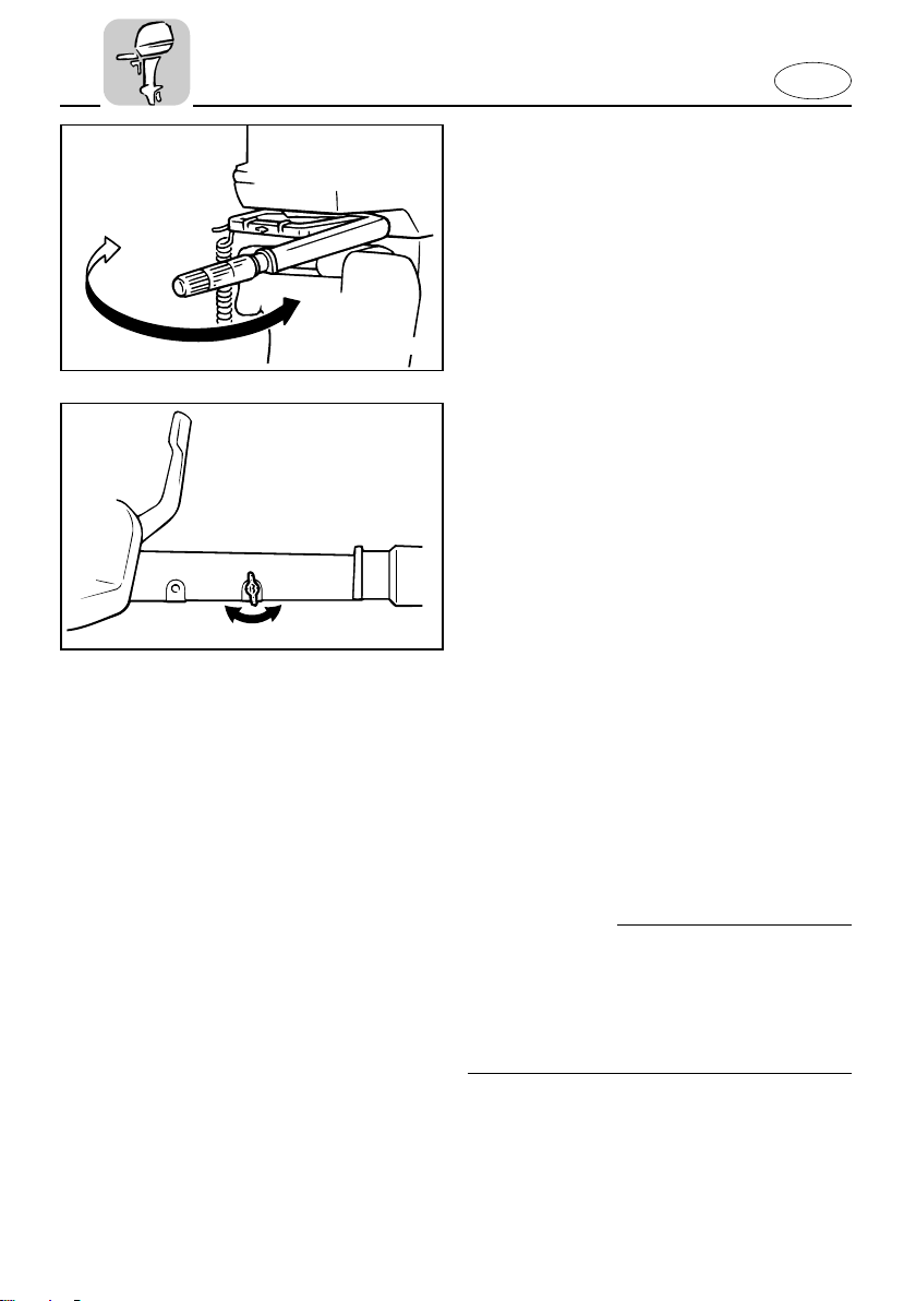
TILLER HANDLE
(for Tiller control model)
Moving the tiller handle sideways to
adjust the steering direction.
EMC64010
Throttle Friction Adjustment
(for Tiller control model)
A friction device in the tiller handle provides resistance to movement of the
throttle grip. This is adjustable for operator preference. An adjusting screw/bolt is
located within the tiller handle.
To increase the resistance:
Turn the adjusting screw/bolt clockwise.
To decrease the resistance:
Turn the adjusting screw/bolt counterclockwise.
When constant speed is desired, tighten
the adjusting screw/bolt to maintain the
desired throttle setting.
w
Do not overtighten the friction adjusting
screw/bolt. If there is too much resistance, it may be difficult to move the
throttle grip, which could result in an
accident.
2-5
408011
402014*
q
E
EMD00010
STEERING FRICTION ADJUSTMENT
(for Tiller control model)
A friction device provides resistance to
steering movement. This is adjustable for
operator preference.
An adjusting screw/bolt is located on the
swivel bracket.
To increase the resistance:
Turn the adjusting screw/bolt clockwise.
To decrease the resistance:
Turn the adjusting screw/bolt counterclockwise.
w
Do not overtighten the friction
screw/bolt. If there is too much resistance, it may be difficult to steer, which
could result in an accident.
EMU01297
TRIM ANGLE ADJUSTING ROD
The position of the trim angle adjusting
rod determines the minimum trim angle
of the outboard motor in relation to the
transom.
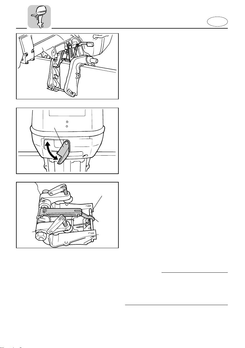
001742
EMD44110
TILT LOCK MECHANISM
(for Manual tilt model)
The tilt-lock mechanism is used to prevent reverse thrust from the propeller lifting the outboard motor when reversing.
To lock it, set the tilt-lock lever in the Lock
position. To release it, place the tilt-lock
lever in the Tilt position.
1 Tilt-lock lever
2-6
q
403013
301012*
q
E
EMD48010
TILT SUPPORT BAR
The tilt support bar keeps the outboard
motor in the tilted up position.
EMD62011
TOP COWLING LOCK LEVER
To remove the engine top cowling, turn
the lock lever. Then lift off the cowling.
When replacing the cowling, check to be
sure it fits properly in the rubber seal.
Then lock the cowling again by moving
the lever upward.
1 Top cowling lock lever
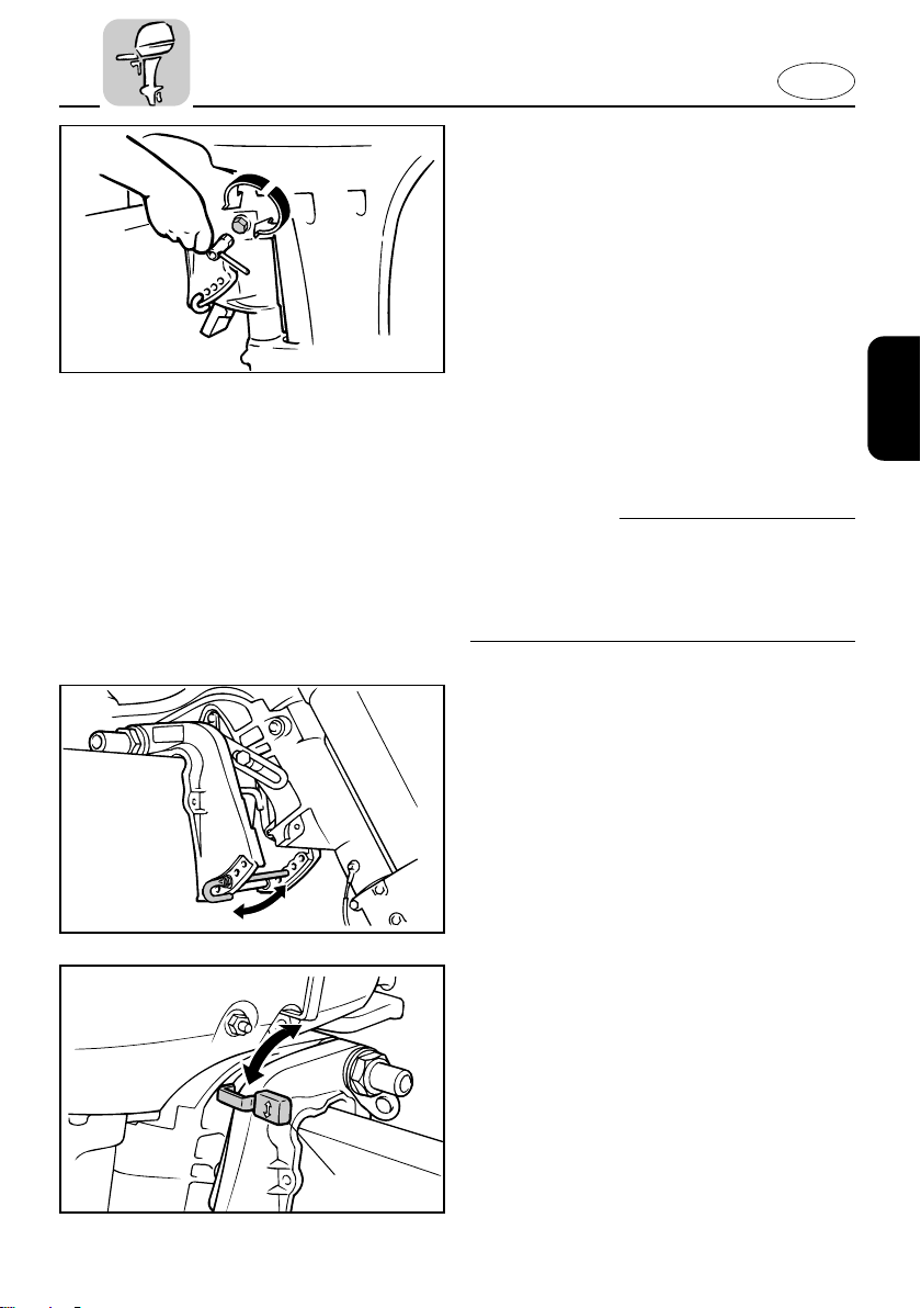
EMD68010*
CARRYING HANDLE
The carrying handle is included between
the clamp bracket. The carrying handle
enables you to carry the outboard motor
readily with one hand after setting it up.
To set up the carrying handle, proceed as
follows.
1) Place the tilt lock lever in the lock
position.
2) Securely hook the arm of carrying
handle end to the clamp bracket bar.
cC
Place the tilt lock lever in the lock position while using the carrying handle. Otherwise, the lower casing may fall to the
grand while carrying the motor.
1 Clamp bracket bar
2-7
E
EMF00010
Chapter 3
OPERATION
INSTALLATION ........................................3-1
Mounting the outboard motor............3-2
Clamping the outboard motor ............3-4
FILLING FUEL AND ENGINE OIL ............3-5
Filling fuel..............................................3-5
Gasoline (petrol) and oil mixing .........3-6
PRE-OPERATION CHECKS ......................3-7
1
2
BREAKING IN (RUNNING IN)
ENGINE .....................................................3-8
STARTING ENGINE ...............................3-10
WARMING UP ENGINE .........................3-13
SHIFTING ................................................3-14
Forward ...............................................3-14
Reverse................................................3-15
STOPPING ENGINE ...............................3-16
TRIMMING OUTBOARD MOTOR.........3-17
Adjusting trim angle ..........................3-18
CRUISING IN SHALLOW WATER.........3-20
TILTING UP/DOWN ...............................3-22
CRUISING IN OTHER CONDITIONS.....3-24
Cruising in salt water .........................3-24
Cruising in turbid water.....................3-24
3
4
5
6

E
EMF10010
INSTALLATION
cC
Incorrect engine height or obstructions to
smooth water flow (such as the design or
condition of the boat or accessories such
as transom ladders/depth finder transducers) can create airborne water spray
while the boat is cruising. Severe engine
damage may result if the motor is operated continuously in the presence of airborne water spray.
NOTE:
During water testing check the buoyancy
of the boat, at rest, with its maximum
load. Check that the static water level on
the exhaust housing is low enough to prevent water entry into the powerhead,
when water rises due to waves when the
outboard is not running.
3-1
E
104011
q
EMU00176
MOUNTING THE OUTBOARD
MOTOR
w
Improper mounting of the outboard
motor could result in hazardous conditions such as poor handling, loss of control, or fire hazards. Observe the following:
8 The information presented in this sec-
tion is intended as reference only. It is
not possible to provide complete
instructions for every possible
boat/motor combination. Proper
mounting depends in part on experience and the specific boat/motor combination.
8 Your dealer or other person experi-
enced in proper rigging should mount
the motor. If you are mounting the
motor yourself, you should be trained
by an experienced person. [permanent
mounted type]
8 Your dealer or other person experi-
enced in proper outboard motor
mounting should show you how to
mount your motor. [portable type]
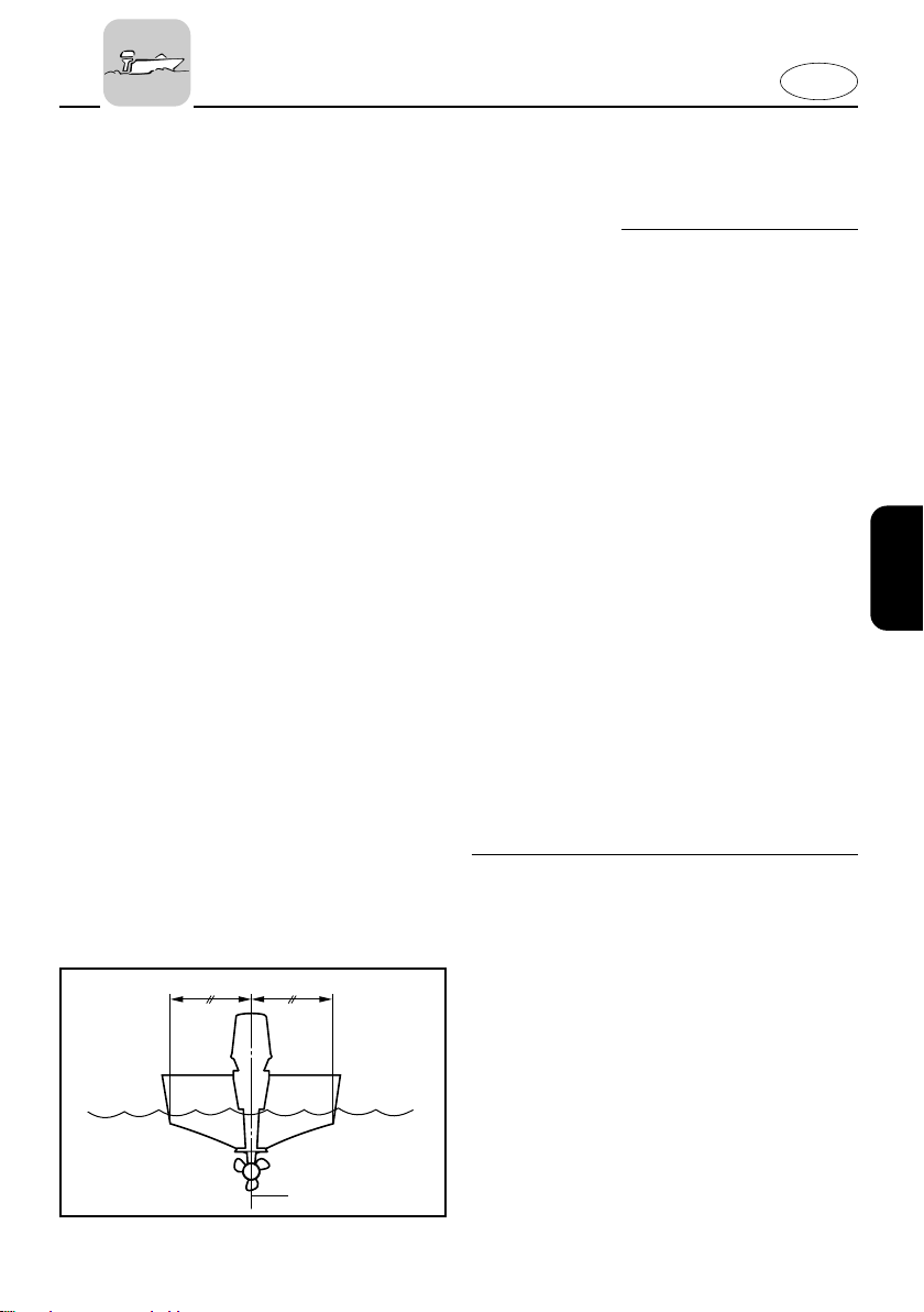
Mount the outboard motor on the center
line (keel line) of the boat, and ensure that
the boat itself is well balanced. Otherwise,
the boat will be hard to steer. For boats
without a keel or which are asymmetrical,
consult your dealer.
1 Center line (keel line)
3-2
Loading...