


FMTRANSCEIVER
FT-1900R
OPERATING MANUAL
VERTEXSTANDARDCO.,LTD.
4-8-8 Nakameguro, Meguro-Ku, Tokyo 153-8644, Japan
VERTEXSTANDARD
USHeadquarters
10900 Walker Street, Cypress, CA 90630, U.S.A.
YAESUUKLTD.
Unit 12, Sun Valley Business Park, Winnall Close Winchester, Hampshire, SO23 0LB, U.K.
VERTEXSTANDARDHKLTD.
Unit 5, 20/F., Seaview Centre, 139-141 Hoi Bun Road, Kwun Tong, Kowloon, Hong Kong
VERTEXSTANDARD(AUSTRALIA)PTY.,LTD.
Normanby Business Park, Unit 14/45 Normanby Road
Notting Hill 3168, Victoria, Australia

CONTENTS
FT-1900RQuickReferenceGuide |
|
Introduction ...................................................... |
1 |
Specifications .................................................... |
2 |
Accessories&Options...................................... |
3 |
SuppliedAccessories ..................................... |
3 |
OptionalAccessories...................................... |
3 |
Installation ........................................................ |
4 |
PreliminaryInspection ................................... |
4 |
InstallationTips.............................................. |
4 |
SafetyInformation.......................................... |
5 |
AntennaConsiderations ................................. |
6 |
MobileInstallation ......................................... |
7 |
MobilePowerConnections........................ |
8 |
MobileSpeakers......................................... |
8 |
BaseStationInstallation................................. |
9 |
ACPowerSupplies.................................... |
9 |
FrontPanelControls&Switches.................. |
10 |
MicrophoneSwitches ..................................... |
12 |
RearPanelConnectors................................... |
13 |
BasicOperation .............................................. |
14 |
TurningtheTransceiverOnandOff............ |
14 |
AdjustingtheAudioVolumeLevel ............. |
14 |
AdjustingtheSquelchSetting...................... |
14 |
FrequencyNavigation .................................. |
15 |
1)TuningDial.......................................... |
15 |
2)DirectKeypadFrequencyEntry .......... |
15 |
3)Scanning .............................................. |
15 |
Transmission ................................................ |
16 |
ChangingtheTransmitterPowerLevel ... |
16 |
AdvancedOperation ...................................... |
17 |
WeatherBroadcastReception...................... |
17 |
LockFeature................................................. |
18 |
KeyboardBeeper.......................................... |
18 |
ChannelStepSelection ................................ |
19 |
DisplayBrightness ....................................... |
19 |
RFSquelch................................................... |
20 |
RepeaterOperation....................................... |
21 |
StandardRepeaterShift ........................... |
21 |
AutomaticRepeaterShift(ARS) ............. |
22 |
CTCSS/DCS/EPCSOperation..................... |
23 |
CTCSSOperation .................................... |
23 |
DCSOperation......................................... |
25 |
ToneSearchScanning.............................. |
26 |
EPCSOperation....................................... |
27 |
CTCSS/DCS/EPCSBellPaging.............. |
29 |
SplitToneOperation................................ |
30 |
DTMFOperation.......................................... |
32 |
ManualDTMFToneGeneration ............. |
32 |
DTMFAutodialer .................................... |
32 |
MemoryOperation......................................... |
34 |
MemoryStorage........................................... |
34 |
SeparateTransmitFrequencyMemory |
|
(“OddSplits”)...................................... |
35 |
MemoryRecall............................................. |
36 |
LabelingMemories ...................................... |
37 |
MemoryTuning............................................ |
38 |
MaskingMemories....................................... |
38 |
MemoryBankOperation.............................. |
39 |
AssigningMemoriestoaMemoryBank .39 |
|
MemoryBankRecall ............................... |
39 |
RemovingMemories |
|
fromaMemoryBank........................... |
40 |
ChangingaMemoryBank’sName.......... |
40 |
HOMEChannelMemory............................. |
41 |
MemoryOnlyMode..................................... |
42 |
Scanning .......................................................... |
44 |
BasicScannerOperation.............................. |
44 |
Scan-ResumeOption.................................... |
45 |
MemorySkipScanning................................ |
46 |
PreferentialMemoryScan............................ |
47 |
MemoryBankLinkScan ............................. |
48 |
ProgrammableBand-ScanLimits................. |
49 |
PriorityChannelScanning(DualWatch)..... |
50 |
PriorityRevertMode ............................... |
50 |
WeatherAlertScan ...................................... |
51 |
BandEdgeBeeper........................................ |
51 |
SmartSearchOperation................................ |
52 |
InternetConnectionFeature ......................... |
54 |
SRGMode.................................................... |
54 |
FRGMode.................................................... |
54 |
ARTS™ ........................................................... |
57 |
BasicARTS™SetupandOperation............ |
57 |
ARTS™PollingTimeOptions .................... |
58 |
ARTS™AlertBeepOptions........................ |
58 |
CWIdentifierSetup ..................................... |
59 |
CWTrainingFeature..................................... |
60 |
PacketOperation............................................ |
61 |
MiscellaneousSettings.................................... |
62 |
Password ...................................................... |
62 |
Time-OutTimer ........................................... |
63 |
AutomaticPower-Off................................... |
63 |
BusyChannelLock-Out............................... |
64 |
ProgrammingtheKeyAssignments............. |
65 |
FMBandwidth&TXDeviationLevel ........ |
66 |
MICGainSetting ......................................... |
66 |
DCSCodeInversion .................................... |
67 |
ResetProcedure.............................................. |
68 |
MicroprocessorResetting............................. |
68 |
SetModeResetting ...................................... |
68 |
Cloning ............................................................ |
69 |
“Set”(Menu)Mode ........................................ |
70 |

FT-1900RQUICKREFERENCEGUIDE
|
|
|
|
|
|
|
|
|
|
|
|
|
|
|
|
|
|||||||||||
|
|
VOLKNOB |
|
|
|
|
|
|
|
|
|
SQLKNOB |
|
|
|||||||||||||
Adjusts the audio |
|
|
|
|
Adjust to the point where the |
||||||||||||||||||||||
volumelevel. |
|
|
|
|
backgroundnoiseismuted. |
||||||||||||||||||||||
|
|
|
|
|
|
|
|
|
|
|
|
|
|
|
|
|
|
|
|
|
|
|
|
|
|||
|
|
|
|
|
|
|
|
|
|
|
|
|
|
|
|
|
|
|
|
|
|
|
|
|
|
|
|
|
|
|
|
|
|
|
|
|
|
|
|
|
|
|
|
|
|
|
|
|
FREQUENCY DIALKNOB |
|
|||||
|
|
|
|
|
|
|
|
|
|
|
|
|
|
|
|
|
|
|
SelectstheoperatingFrequency. |
||||||||
|
|
|
|
|
|
|
|
|
|
|
|
|
|
|
|
|
|
|
|
|
|
|
|
|
|
|
|
|
|
|
|
|
|
|
|
|
|
|
|
|
|
|
|
|
|
|
|
|
|
|
|
|
|
|
|
|
|
|
|
|
|
|
|
|
|
|
|
|
|
|
|
|
|
|
|
|
|
|
|
|
|
|
|
|
|
|
|
|
|
|
|
|
|
|
|
|
|
|
|
|
|
|
|
|
|
|
|
|
|
|
|
|
|
|
|
|
|
|
|
|
|
|
|
|
|
|
|
|
|
|
|
|
|
|
|
|
|
|
|
|
|
|
|
|
|
|
|
|
|
|
|
|
|
|
|
|
|
|
|
|
|
|
|
|
|
|
|
|
|
|
|
|
|
|
|
|
|
|
|
|
|
|
|
|
|
|
|
|
|
|
|
|
|
|
|
|
|
|
|
|
|
|
|
|
|
|
|
|
|
|
|
|
|
|
|
|
|
|
|
|
|
|
|
|
|
|
|
|
|
|
|
|
|
|
|
|
|
|
|
|
|
|
|
|
|
|
|
|
|
|
|
|
|
|
|
|
|
|
|
|
|
|
|
|
|
|
|
|
|
|
|
|
|
|
|
|
|
|
|
|
|
|
|
|
|
|
|
|
|
|
|
|
|
|
|
|
|
|
|
|
|
|
|
|
|
|
|
|
|
|
|
|
|
|
|
|
|
|
|
|
|
|
|
|
|
|
|
|
|
|
|
|
|
|
|
|
POWER SWITCH |
|
|
|
LOCKSWITCH |
|
|
|
|
|
|
||
|
Press and hold for |
|
Pressand hold for one second to lock all |
|||
|
onesecond. |
|
keyfunctionsexcepttheVOL,SQLknobs |
|||
|
|
|
|
andPTTswitch. |
||
|
|
|
|
|||
|
|
|
|
|
|
|
TRANSMISSION SWITCH |
|
Speakintothemicrophone |
MICROPHONE |
|
|
in a normal voice level |
|
whilepressingthisswitch. |
|
DTMF MICROPHONE
MH-48
FT-1900RQUICKREFERENCEGUIDE
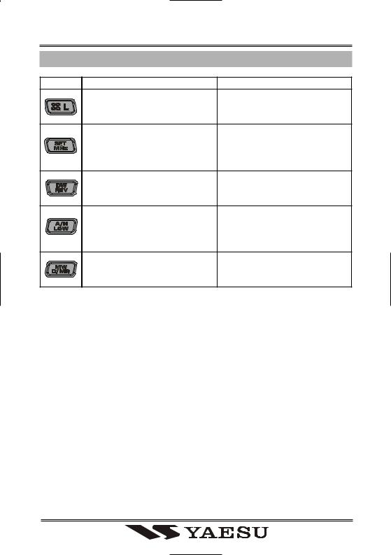
KEY OVERVIEW
KEY |
PRESS KEY BRIEFLY |
PRESS AND HOLD KEY |
|
ActivatestheInternetConnec- |
Locks out the switches and |
|
tion Feature. |
knobs (except the VOL, SQL |
|
|
knobs and PTT switch). |
|
Allows tuning the VFO fre- |
EnterstheSet(“Menu”)mode. |
|
quencyin1-MHzsteps,ortun- |
|
|
ing channels in 10 channel |
|
|
steps. |
|
|
Reverses transmitandreceive |
Activates the Priority Channel |
|
frequenciesinrepeateropera- |
Scanning (Dual Watch fea- |
|
tion. |
ture). |
|
Selects the transmitter power |
Toggles the display indication |
|
output level. |
between “frequency” and the |
|
|
channel’s “Alpha/Numeric |
|
|
Tag”. |
|
Switchesthefrequencycontrol |
Transfers the VFO contents |
|
betweentheVFO,MemorySys- |
into a Memory register. |
|
tem,andtheHomechannel. |
|

INTRODUCTION
The Yaesu FT-1900R is a deluxe, rugged FM mobile transceiver providing high power output and outstanding receiver performance for the 144 MHzAmateur band. Included in the FT-1900R’s feature complement are:
55Watts of power output, with selection of four power levels for every operating situation.
Expanded receiver coverage: 136-174 MHz.
Keyboard entry of operating frequencies from the microphone.
Excellentprotectionfromreceiverintermodulationdistortion,thankstoYaesu’srenowned AdvancedTrackTuning front end.
221 memories (200 “basic” memory channels, 10 sets of band-edge memory channels, and one “Home” channel) which can store repeater shifts, odd repeater shifts, CTCSS/ DCS tones, and 6-characterAlpha-Numeric labels for easy channel recognition.
10 NOAAWeather Broadcast Channels, with WeatherAlert and a Volume Control for theWeatherAlert tone.
Built-in CTCSS and DCS Encoder/Decoder circuits.
The Smart SearchTM feature, which automatically sweeps a band and loads active frequencies into dedicated memory banks, is ideal for identifying active repeaters when visiting a city for the first time.
ExtensiveMenusystem,whichallowscustomizationofanumberoftransceiverperformance characteristics.
TheYaesu-exclusive multi-function LCD display.
AdditionalfeaturesincludeatransmitTime-Out-Timer(TOT),AutomaticPower-Off(APO), Automatic Repeater Shift (ARS), plus provision for reduction of theTx deviation in areas of high channel congestion.And an RF Squelch circuit allows the owner to set the squelch to open at a programmable setting of the S-Meter, thus reducing guesswork in setting the squelch threshold.
Congratulations on your purchase of the FT-1900R! Whether this is your first rig, or if Yaesu equipment isalreadythebackboneofyourstation,theVertexStandard organization iscommittedtoensuringyourenjoymentofthishigh-performancetransceiver,whichshould provide you with many years of satisfying operation. Our dealer network and technical support personnel stand behind every product we sell, and we invite you to contact us should you require technical advice or assistance.
We recommend that you read this manual in its entirety prior to installing the FT-1900R, so that you fully understand the capabilities of your new transceiver.
FT-1900ROPERATING MANUAL |
1 |

SPECIFICATIONS
GENERAL |
|
FrequencyRange: |
Tx 144 - 146 MHz or 144 - 148 MHz |
|
Rx 144 - 146 MHz or 136 - 174 MHz |
ChannelStep: |
5/10/12.5/15/20/25/50/100 kHz |
StandardRepeaterShift: |
±600 kHz |
FrequencyStability: |
Better than ±10 ppm |
|
[–4 °F to +140 °F (–20 °C to +60 °C)] |
ModesofEmission: |
F2D/F3E |
AntennaImpedance: |
50 Ohms, unbalanced |
Supplyvoltage: |
13.8VDC ±15%, negative ground |
CurrentConsumption(typical): Rx: less than 0.7A, less than 0.3A(squelched) |
|
|
Tx: 11A(55W) /7A(25W) /5A(10W) /4A(5W) |
OperatingTemperatureRange: –4° F to +140° F (–20° C to +60° C) |
|
CaseSize(WxHxD): |
5.5” x 1.6” x 5.7” (140 x 40 x 146 mm) (w/o knobs) |
Weight(Approx.): |
2.6 lb (1.2 kg) |
TRANSMITTER |
|
OutputPower: |
55 W/25 W/10 W/5 W |
ModulationType: |
Variable Reactance |
MaximumDeviation: |
±5 kHz (Wide) |
|
±2.5 kHz (Narrow) |
SpuriousRadiation: |
Better than –60 dB |
MicrophoneImpedance: |
2 k-Ohms |
RECEIVER |
|
CircuitType: |
Double Conversion Superheterodyne |
Ifs: |
21.7 MHz & 450 kHz |
Sensitivity(for 12dB SINAD): |
Better than 0.2 µV |
Selectivity(–6/–60dB): |
12 kHz/28 kHz (Wide) |
|
9 kHz/22 kHz (Narrow) |
IFRejection: |
Better than 70 dB |
ImageRejection: |
Better than 70 dB |
MaximumAFOutput: |
3Winto 4 Ohms @10 %THD |
Specificationssubjecttochangewithoutnoticeorobligation.Specificationsguaranteed onlywithinAmateurband.
Frequencyrangeswillvaryaccordingtotransceiverversion;checkwithyourdealer.
2 |
FT-1900ROPERATING MANUAL |

|
A CCESSORIES & O PTIONS |
|
|
S UPPLIED A CCESSORIES |
|
Microphone MH-48A6J |
...................................................................................................... |
1 |
Mobile Mounting Bracket MMB-36.................................................................................. |
1 |
|
DC Power Cord w/Fuse .................................................................................(T9021715) |
1 |
|
Spare Fuse 15A(Q0000081) ............................................................................................. |
2 |
|
Operating Manual............................................................................................................... |
|
1 |
Warranty Card .................................................................................................................... |
|
1 |
|
O PTIONAL A CCESSORIES |
|
High-Power External Speaker MLS-100 |
|
|
AC Power Supply |
FP - 1023 (25 A: USA only) |
|
AC Power Supply |
FP - 1030A (25 A) |
|
Availabilityofaccessoriesmayvary.Someaccessoriesaresuppliedasstandardperlocal requirements,whileothersmaybeunavailableinsomeregions.Thisproductisdesignedto performoptimallywhenusedwithgenuineVertexStandardaccessories.VertexStandard shallnotbeliableforanydamagetothisproductand/oraccidentssuchasfire,leakageor explosionofabatterypack,etc.,causedbythemalfunctionofnon-VertexStandardacces- sories.ConsultyourVertexStandarddealerfordetailsregardingtheseandanynewly- availableoptions.Connectionofanynon-VertexStandard-approvedaccessory,shouldit causedamage,mayvoidtheLimitedWarrantyonthisapparatus.
FT-1900ROPERATING MANUAL |
3 |

INSTALLATION
Thischapter describes the installation procedure for integrating theFT-1900Rinto a typicalamateurradiostation.Itispresumedthatyoupossesstechnicalknowledgeandconceptualunderstandingconsistentwithyourstatusasalicensedradioamateur.Pleasetakesome extra time to make certain that the important safety and technical requirements detailed in this chapter are followed closely.
PRELIMINARY INSPECTION
Inspect the transceiver visually immediately upon opening the packing carton. Confirm that all controls and switches work freely, and inspect the cabinet for any damage. Gently shake the transceiver to verify that no internal components have been shaken loose due to rough handling during shipping.
If any evidence of damage is discovered, document it thoroughly and contact the shipping company (or your local dealer, if the unit was purchased over-the-counter) so as to get instructionsregardingthepromptresolutionofthedamagesituation.Becertaintosavethe shippingcarton,especiallyifthereareanypuncturesorotherevidenceofdamageincurred during shipping; if it is necessary to return the unit for service or replacement, use the originalpackingmaterialsbutputtheentirepackageinsideanotherpackingcarton,soasto preserve the evidence of shipping damage for insurance purposes.
INSTALLATION TIPS
Toensurelonglifeofthecomponents,becertaintoprovideadequateventilationaroundthe cabinet of the FT-1900R.
Do not install the transceiver on top of another heat-generating device (such as a power supplyoramplifier),anddonotplaceequipment,books,orpapersontopoftheFT-1900R. Avoid heating vents and window locations that could expose the transceiver to excessive directsunlight,especiallyinhotclimates.TheFT-1900Rshouldnotbeusedinanenviron- ment where the ambient temperature exceeds +140 °F (+60 °C).
4 |
FT-1900ROPERATING MANUAL |
INSTALLATION
SAFETY INFORMATION
The FT-1900Ris an electrical apparatus, as well as a generator of RF (Radio Frequency) energy, and you should exercise all safety precautions as are appropriate for this type of device. These safety tips apply to any device installed in a well-designed amateur radio station.
Never allow unsupervised children to play in the vicinity of your transceiver or 
 antenna installation.
Be certain to wrap any wire or cable splices thoroughly with insulating electrical 
 tape, to prevent short circuits.
Do not route cables or wires through door jambs or other locations where, through 
 wear and tear, they may become frayed and shorted to ground or to each other.
 Do not stand in front of a directional antenna while you are transmitting into that
 antenna. Do not install a directional antenna in any location where humans or pets
may be walking in the main directional lobe of the antenna’s radiation pattern.
 In mobile installations, it is preferable to mount your antenna on top of the roof of
 thevehicle,iffeasible,soastoutilizethecarbodyasacounterpoisefortheantenna
and raise the radiation pattern as far away from passengers as possible.
During vehicular operation when stopped (in a parking lot, for example), make it a

 practice to switch to Low power if there are people walking nearby.
  Never wear dual-earmuff headphones while driving a vehicle.
 Donotattempttodriveyourvehiclewhilemakingatelephonecallonanautopatch
 using the DTMF microphone. Pull over to the side of the road, whether dialing
manually or using the auto-dial feature.
FT-1900ROPERATING MANUAL |
5 |

INSTALLATION
ANTENNA CONSIDERATION
The FT-1900R is designed for use with antennas presenting an impedance of near 50 Ohms at all operating frequencies. The antenna (or a 50 Ohm dummy load) should be connected whenever the transceiver is turned on, to avoid damage that could otherwise result if transmission occurs accidentally without an antenna.
Ensure that your antenna is designed to handle 50Watts of transmitter power. Some mag- netic-mount mobile antennas, designed for use with hand-held transceivers, may not be capableofwithstandingthispowerlevel.Consulttheantennamanufacturer’sspecification sheet for details.
Most all FM work is performed using vertical polarization. When installing a directional antenna such as a Yagi or Cubical Quad, be certain to orient it so as to produce vertical polarization, unless you are engaged in a special operating situation where horizontal polarization is used. In the case of aYagi antenna, orient the elements vertically for vertical polarization;foraCubicalQuad,thefeedpointshouldbeatthecenterofoneofthevertical sides of the driven element (or at a side corner, in the case of a diamond-shaped “Delta Loop”).
Excellent reference texts and computer software are available for the design and optimization of VHF antennas. Your dealer should be able to assist you with all aspects of your antenna installation requirements.
Use high-quality 50 Ohm coaxial cable for the lead-in to your FT-1900Rtransceiver.All effortsatprovidinganefficientantennasystemwillbewastedifpoorquality,lossycoaxial cable is used. Losses in coaxial lines increase as the frequency increases, so an 8-meter- long (25’ coaxial line with 1/2 dB of loss at 29 MHz may have a loss of 1.8 dB or more at 146MHz;chooseyourcoaxialcablecarefullybasedontheinstallationlocation(mobilevs. base) and the overall length of the cable required (for very short runs of cable in a mobile installation, the smaller, more flexible cable types may be acceptable).
For reference, the chart at the right shows ap- |
LossindBper30m(100feet)for |
||
proximate loss figures for typically-available |
Selected50-OhmCoaxialCables |
||
coaxial cables frequently used inVHF instal- |
(Assumes50-ohmInput/OutputTerminations) |
||
lations. |
CABLE TYPE |
LOSS:144MHZ |
|
|
RG-58A |
6.5 |
|
Inoutdoorinstallations,becertaintoweather- |
RG-58 Foam |
4.7 |
|
RG-213 |
3.0 |
||
proof all connectors thoroughly, as water en- |
|||
RG-8 Foam |
2.0 |
||
|
|||
teringacoaxialcablewillcauselossestoesca- |
Belden 9913 |
1.5 |
|
late rapidly, thus diminishing your communi- |
Times Microwave LMR-400 |
1.5 |
|
7/8” “Hardline” |
0.7 |
||
|
|||
cations effectiveness. The use of the shortest |
Lossfiguresareapproximate;consultcablemanufac- |
||
possible length of the highest quality coaxial |
turers’catalogsforcompletespecifications. |
||
cable that fitswithin yourbudget willensure thebest performance from yourFT-1900R.
6 |
FT-1900ROPERATING MANUAL |
INSTALLATION
MOBILE INSTALLATION
TheFT-1900Rmustonlybeinstalledinvehicleshavinga13.8Voltnegativegroundelec- tricalsystem.Mountthetransceiverwherethedisplay,controls,andmicrophoneareeasily accessible, using the supplied MMB-36mounting bracket.
The transceiver may be installed in almost any location, but should not be positioned near a heating vent nor anywhere where it might interfere with driving (either visually or mechanically). Make sure to provide plenty of space on all sides of the transceiver so that air can flow freely around the radio’s case. Refer to the diagrams showing proper installation procedures.
MMB-36Installation
FT-1900ROPERATING MANUAL |
7 |

INSTALLATION
MOBILE INSTALLATION
MobilePowerConnections
To minimize voltage drop and avoid blowing the vehicle’s fuses, connect the supplied DC power cable directly to the battery terminals. Do not attempt to defeat or bypass the DC cable’sfuse-itistheretoprotectyou,yourtransceiver,andyourvehicle’selectricalsystem.
Warning!
Never applyAC power to the power cable of the FT-1900R, nor DC voltage greater than 15.8 Volts. When replacing the fuse, only use a 15-Afuse. Failure to observe these safety precautions will void the LimitedWarranty on this product.
Before connecting the transceiver, check the voltage at the battery terminals while revving the engine. If the voltage exceeds 15 Volts, adjust the vehicle’s voltage regulator before proceeding with installation.
ConnecttheREDpowercableleadtothePOSITIVE(+)batteryterminal,andtheBLACK powercableleadtotheNEGATIVE(–)terminal.Ifyouneedtoextendthepowercable, use #12AWG or larger insulated, stranded copper wire. Solder the splice connections carefully,and wrapthe connectionsthoroughlywithinsulating electricaltape.
Before connecting the cable to the transceiver, verify the voltage and polarity of the voltage at the transceiver end of the DC cable using a DC voltmeter. Now connect the transceiver to the DC cable.
WARNING!
NEVER remove the FUSE 
 holders from the DC cable.
Cabin Engine Room
FT-1900R
Battery
|
RED: Positive (+) |
Fuse 15A |
BLACK: Negative (–) |
Fuse Holder
MobileSpeakers
The optional MLS-100External Speaker includes its own swivel-type mounting bracket, and is available from yourYaesu dealer.
OtherexternalspeakersmaybeusedwiththeFT-1900R,iftheypresentthespecified4-Ohm impedanceandarecapableofhandlingthe3WattsofaudiooutputsuppliedbytheFT-1900R.
8 |
FT-1900ROPERATING MANUAL |

INSTALLATION
BASE STATION INSTALLATION
The FT-1900R is ideal for base station use as well as in mobile installations. The FT1900Ris specifically designed to integrate into your station easily, using the information to follow as a reference.
ACPowerSupplies
OperationoftheFT-1900RfromanAClinerequiresapowersourcecapableofproviding at least 11Amps continuously at 13.8Volts DC.The FP-1023and FP-1030AAC Power Supplies are available from your Yaesu dealer to satisfy these requirements. Other wellregulated power supplies may be used, as well, if they meet the above voltage and current specifications.
Use the DC power cable supplied with your transceiver for making power connections to the power supply. Connect the REDpower cable lead to the POSITIVE(+) power supply terminal, and connect the BLACKpower cable lead to the NEGATIVE(–) power supply terminal.
FT-1900ROPERATING MANUAL |
9 |
FRONT PANEL CONTROLS &SWITCHES
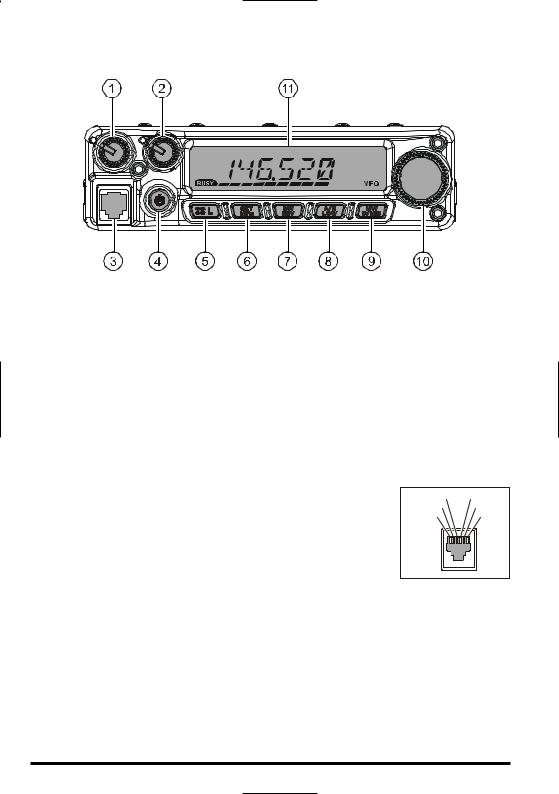
 VOLKnob
This control adjusts the audio volume level. Clockwise rotation increases the volume level.
 SQLKnob
Thiscontrolisusedtosilencebackgroundnoiseonthereceiver.Itshouldbeadvanced clockwise just to the point where the noise is silenced (and the “ ” indicator on the display turns off), so as to provide the best sensitivity to weak signals.
 MicrophoneJack
Connect the supplied MH-48A6J Hand Microphone to this jack.
 PWRKey
Pressandholdthiskeyforonesecondtotogglethetransceiver’s power on and off.
 [
[

 (L)]Key
GND |
+8V |
MIC INPUT |
MIC SW1 |
PTT/CLONE |
MIC SW2 |
This key allows operation in conjunction with the Internet Connection feature.
Press and hold in this key for one second to toggle the Lockout Feature “on” or “off”.
 [MHz(SET)]Key
This key allows tuning in 1-MHz steps (the MHz digits will blink on the display). If receiving on a memory, pressing this key the first time activates the Memory Tuning mode, and pressing it again enables 1-MHz steps.
Press and hold in this key for one second to activate the “Set” (Menu) mode.
10 |
FT-1900ROPERATING MANUAL |

FRONT PANEL CONTROLS &SWITCHES
 [REV(DW)]Key
Duringsplit-frequencyoperation,suchasthrougharepeater,thiskeyreversesthetrans- mit and receive frequencies.
PressandholdinthiskeyforonesecondtoactivatetheDualWatchfeature,described in the Operation chapter (“PRI” will be displayed on the LCD, indicating “Priority Channel” monitoring).
 [LOW(A/N)]Key
Press this key momentarily to select the transmitter power output level. The available power levels are:
LOW1 (5W) LOW2 (10W) LOW3 (25W) HIGH (50 W)
To toggle the display between indication of the frequency and the channel’sAlpha/ Numericlabel,pressandholdinthiskeyforonesecondwhilereceivingonthatmemory channel.
 [D/MR(MW)]Key
Press this key momentarily to switch the frequency control among theVFO, Memory System, and Home channel.
Press and hold in this key for one second to activate the Memory Storage mode.
 DIALKnob
This24-position detentedrotary switch is usedfor tuning, memory selectionand most functionsettings.Themicrophone[UP]/[DWN]buttonsduplicatethefunctionsofthis knob.
 Display
The main digits on the display may show the operating frequency, memory name, or any of many parameters during Menu setup.
|
CTCSS/DCS/EPCS Bell Paging |
DTMF Memory Mode |
||||||||
CTCSS |
DCS (Digital Code Squelch) |
|
Lock Feature Active |
|||||||
|
|
|
|
|
|
|
|
|
|
|
(Continuous Tone Coded Squelch System) |
|
Programmable Memory Scan |
||||||||
|
Repeater Shift Direction |
|
SKIP/Preferential Scan Channel |
|||||||
|
TX Indicator |
|
|
|
|
|
|
Priority Channel |
||
|
|
|
|
|
|
|
Memory Mode |
|||
|
|
|
|
|
||||||
|
Narrow Deviation |
|
|
|
|
|
|
|
|
|
|
|
|
|
|
|
|
|
|
||
|
|
|
|
|
|
|
Memory Channel Number |
|||
Low TX Power Selected |
|
|
|
|||||||
|
|
|
||||||||
|
|
|
VFO Mode |
|||||||
|
BUSY Indicator |
|
|
|
|
|||||
|
|
|
|
|
|
|||||
|
|
|
|
|
|
|
|
|||
|
|
|
|
|
S- and TX Power Meter |
Home Channel |
||||
|
|
|
|
|
|
|
Frequency/Message Area |
|||
FT-1900ROPERATING MANUAL |
11 |
MICROPHONE SWITCHES
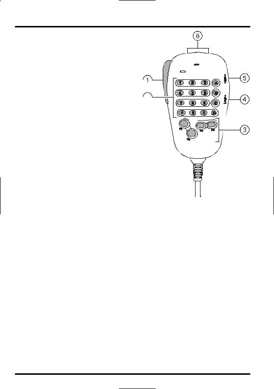
 PTTSwitch
Press this switch to transmit, and release it to receive.
 Keypad
These 16 keys generate DTMF tones during transmission. 
In the receive mode, these 16 keys can be used for direct frequency entry and/or di-  rectnumericrecalloftheMemorychannels. The[A],[B], [C],and[D]keys,onreceive, replicatethefunctionsofthefrontpanelkeys ([MHz(SET)], [REV(DW)], [LOW(A/N)], and[D/MR(MW)]).Seethepreviousdiscussion.
DTMF MICROPHONE
MH-48
 [P1]/[P2]/[P3]/[P4]Buttons
Thesefourkeysareuserprogrammable,allowing quick access to features used often. The default functions are described below.
[P1] button (SQLOFF) 

 Press this button to disable the noise and tone squelch systems. [P2] button (SSRCH)
Press this button to activate the Smart Search feature. [P3] button (CSRCH)
Press this button to activate theTone Search feature. [P4] button (WXCH/T.CALL)
IntheUSAversion,pressingthisbuttonrecallsthe“Weather”broadcastchannelbank. IntheEXPversion,pressingthisbuttonactivatesT.CALL(1750Hz)forrepeateraccess. You can reprogram the [P1], [P2], [P3], and [P4] buttons for other functions, if desired. See page 65 for details.
 LAMPSwitch
This switch illuminates the Microphone’s keypad.
 LOCKSwitch
ThisswitchlocksouttheMicrophone’sbuttons(exceptforthekeypadandPTTswitch).
 [UP]/[DWN]Button
Press (or hold in) either of these buttons to tune (or scan up or down) the operating frequency or through the memory channels. In many ways, these buttons emulate the function of the (rotary) DIALknob.
12 |
FT-1900ROPERATING MANUAL |
REAR PANEL CONNECTORS
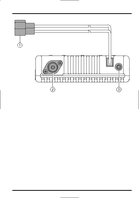
 13.8VDCCablePigtail
This is the power supply connection for the transceiver. Use the supplied DC cable to connect this pigtail to the car battery or other DC power supply capable of at least 11 Amperes(continuousduty).Makecertainthattheredleadconnectstothepositiveside of the supply.The fuse is 15-A.
 ANTCoaxialSocket
Connect a 144-MHz antenna to this type-M (SO-239) socket using 50-Ohm coaxial cable and a type-M (PL-259) plug. Make sure the antenna is designed specifically for use on the operating frequency.
 EXTSPJack
This 2-contact 3.5-mm mini phone jack provides receiver audio output for an optional externalspeaker.Theaudioimpedanceis4Ohms,andthelevelvariesaccordingtothe setting of the front panel’s VOLcontrol. Inserting a plug into this jack disables audio from the transceiver’s internal speaker.
FT-1900ROPERATING MANUAL |
13 |

BASIC OPERATION


 Hi!I’mR.F.Radio,andI’llbehelpingyoualongasyoulearnthemanyfeatures


 oftheFT-1900R.Iknowyou’reanxioustogetontheair,butIencourageyouto read the “Basic Operation” section of this manual as thoroughly as possible, so you’ll
getthe mostoutofthisfantastic newtransceiver.Now.. .let’sget operating!
TURNING THE TRANSCEIVER ON AND OFF
1. To turn the transceiver on, press and hold in the PWR key for one second.
WhenyouturnontheFT-1900R,thecurrentDCsupply voltageisindicatedontheLCDfor2seconds.Afterthis interval, the display will switch its normal indication of the operating frequency.
2.To turn the transceiver off, again press and hold in the PWRkey for one second.


 You can change the Opening Message (DC supply voltage indication) to any de-


 sired message (up to 6 characters) via Set Mode Item “31 OPN.MSG;” see page
76 for details.
ADJUSTING THE AUDIO VOLUME LEVEL
RotatetheVOLcontroltoadjustthereceivervolume.Clock-  wise rotation increases the audio output level.


ADJUSTING THE SQUELCH SETTING
Rotate the SQLcontrol just to the point where the noise is
silencedandthe“ ”indicatoronthedisplayturnsoff.If theSQLcontrolissetfurtherclockwise,sensitivitytoweak signals is reduced.
A special “RF Squelch” feature is provided on this radio. This feature allows you to set the squelch so that only sig- nalsexceedingacertainS-meterlevelwillopenthesquelch.
See page 20 for details
14 |
FT-1900ROPERATING MANUAL |

BASIC OPERATION
FREQUENCY NAVIGATION
1)TuningDial
RotatingtheDIALknoballowstuninginthepre-programmedsteps.Clockwiserotationofthe DIALknobcausestheFT-1900Rtobetunedtowardahigherfrequency,whilecounter-clock- wiserotationwilllowertheoperatingfrequency.
Pressthe[MHz(SET)]keymomentarily,thenrotatetheDIALknob,tochangethefrequency stepsto1MHzperstep.Thisfeatureisextremelyusefulformakingrapidfrequencyexcursions overthewidetuningrangeoftheFT-1900R.Insteadofpressingthe[MHz(SET)]button,you mayalsopressthe[A]keyontheMicrophone’skeypadtoengagetuningin1MHzsteps.
2)DirectKeypadFrequencyEntry
ThekeypadoftheMH-48A6J DTMFMicrophonemaybeusedfordirectentryoftheoperating frequency.
ToenterafrequencyfromtheMH-48A6J keypad,justpressthenumbereddigitsintheproper sequence. There is no “decimal point” key on the MH-48A6J keypad. However, there is a short-cutforfrequenciesendinginzero:pressthe[#]key after the last non-zero digit.
Examples:To enter 146.520 MHz, press [1] [4] [6] [5] [2] [0]
To enter 146.000 MHz, press [1] [4] [6] [#]


 If you cannot get the radio to accept the frequency entry, it is possible that the


 channel steps are set to an incompatible value (e.g. if you have 25 kHz steps set, you cannot set a frequency of 146.520 MHz). See page 19 to learn how to change the
channel step size.
3)Scanning
From the VFO mode, press the microphone’s [UP]/[DWN] keys momentarily to initiate scanningtowardahigher-orlowerfrequency,respectively.TheFT-1900Rwillstopwhen it receives a signal strong enough to break through the squelch threshold. The FT-1900R willthenholdonthatfrequencyaccordingtothesettingofthe“Resume”mode(Menu“41 SCAN)”; see page 45).
If you wish to reverse the direction of the scan (i.e. toward a lower frequency, instead of a higher frequency), just rotate the DIALknob one click in the counter-clockwise direction while the FT-1900R is scanning. The scanning direction will be reversed. To revert to scanningtowardahigherfrequencyoncemore,rotatetheDIALknoboneclickclockwise.
Press the [UP]/[DWN]keys again to cancel scanning.You may also press thePTTbutton momentarily;scanningwillstop,butyouwillnottransmituntilyoureleasethePTTbutton, and press it again.


 Ifyouhaveenabledthe“SevereWeatherAlert”feature,youwilloccasionallyno-


 tice“WX”channelsinterspersedwiththeregularchannelsyouarescanning.This isnormal,becauseyourradioisconstantlymonitoringforweatheralerts.Seepage17.
FT-1900ROPERATING MANUAL |
15 |

BASIC OPERATION
TRANSMISSION
To transmit, simply close the PTT (Push To Talk) switch on the microphone when the frequency is clear. Hold the microphone approximately 1” (25 mm) from your mouth, and speak into the microphone in a normal voice level. When your transmission is complete, release the PTTswitch; the transceiver will revert to the receive mode.
Duringtransmission,the“ ”indicatorwillappearattheupperleftcorneronthedisplay.
ChangingtheTransmitterPowerLevel
You can select from among a total of four transmit power levels on your FT-1900R.
To change the power level, press the [LOW(A/N)] key (or the microphone’s [C] key to selectoneoffourpowersettings.Thesepowerlevelswillbestored,inmemoryregisters,at the time of memory storage (see page 34 for details on Memory operation).
During transmission, the Bar Graph will deflect in the display, according to the power output selected.
Low1(5 watts)
Low2(10 watts)
Low3(25 watts)
HIGH(55 watts)
16 |
FT-1900ROPERATING MANUAL |
ADVANCED OPERATION
WEATHER BROADCAST RECEPTION (USAVERSION)
The FT-1900Rincludes a unique feature which allows reception of weather broadcasts in the 160-MHz frequency range. Ten standard Weather Broadcast channels are pre-loaded into a special memory bank.
To listen to aWeather Broadcast Channel:
1. Press the Microphone’s [P4] button to recall the Weather 


 Broadcast channels.


2. Turn the DIALknob to select the desiredWeather Broadcast channel.
3. Ifyouwishtochecktheotherchannelsforactivity  by scanning, just press the Microphone’s PTT
switch.
4. To exit to normal operation, press the[P4]button again.OperationwillreturntotheVFOorMemory
channel you were operating on before you beganWeather Broadcast operation.


 The [P4] key, one of the programmable keys, is assigned (default setting) as the


 “WX Broadcast” one-touch access key. Please note that if you change/assign another function to the [P4] key, one-touch access to the WX channel will be unavail-
able.
SevereWeatherAlertFeature
In the event of extreme weather disturbances, such as storms and hurricanes, NOAA (the National Oceanic andAtmosphericAdministration) sends a weather alert accompanied by a1050HztoneandsubsequentweatherreportononeoftheNOAAweatherchannels.You may enable this feature via Menu Item “57WXALT,” if desired. See page 49 for details.
When scanning the band or the “regular” memories, with the SevereWeatherAlert feature engaged, you will notice that the FT-1900Rwill break over to theWeather Channel bank every five seconds, performing a quick scan of those channels in search for the 1050 Hz alert tone. If the alert tone is received, operation will lock on the weather broadcast station issuing the alert; otherwise, the radio will revert to the VFO or memory scan session in progress without interruption.
Whenthealerttoneisreceived,pressthePTTbuttonmomentarilytodisablethealarm,and the SevereWeather message will now be audible from the speaker.
FT-1900ROPERATING MANUAL |
17 |

ADVANCED OPERATION
LOCKFEATURE
To activate the locking feature, press and hold in the [
 (L)]
(L)]
key for one second.The “ ” icon will appear on the LCD.


 To cancel locking, press and hold in the [
 (L)] key again for
one second.
In order to prevent accidental frequency change or inadvertent transmission, various aspects of the FT-1900R’s keys and knob may be locked out.
To lock out some or all of the keys, use the “Set” (Menu) mode, described below: 1. Pressandholdinthe[MHz(SET)]keyforonesecond,then
rotate the DIALknob to select “26 LOCK.” 


 2. Press the [MHz(SET)] key, then rotate the DIALknob to
select the desired lockout combination. KEY: Just the front panel keys are locked out.
DIAL: Just the front panel DIALknob is locked out.
K+D: Both the keys and DIALknob are locked out.
PTT: The PTTswitch is locked (TX not possible).
K+P: Both keys and PTTswitch are locked out. D+P: Both DIALknob and PTTswitch are locked out. ALL: All of the above are locked out.
3.Press and hold in the [MHz(SET)] key for one second to save the new setting and exit to normal operation.
KEYBOARD BEEPER
Akey/buttonbeeperprovidesusefulaudiblefeedbackwheneverakey/buttonispressed.If you want to turn the beeper off (or back on again):
1. Pressandholdinthe[MHz(SET)]keyforonesecond,then rotatetheDIALknobtoselect“6 BEEP.”
2. Press the [MHz(SET)] key, then rotate the DIALknob to setthedisplayto“OFF.”
3. Press and hold in the [MHz(SET)] key for one second to save your new setting and exit to normal operation.
4.To turn the beep back on again, select “KEY”or“KY+SCN (factory default)” in step 4 above.
KEY: The beeper sounds when you press the keypad.
KY+SCN:The beeper sounds when you press the keypad, or when the scanner stops.
18 |
FT-1900ROPERATING MANUAL |
ADVANCED OPERATION
CHANNEL STEP SELECTION
Tuning steps are factory preset to default increments which are appropriate for the country towhichthisradioisexported.Youmayhaveareasontouseadifferentstepsize,however, and here is the procedure for changing the channel steps:
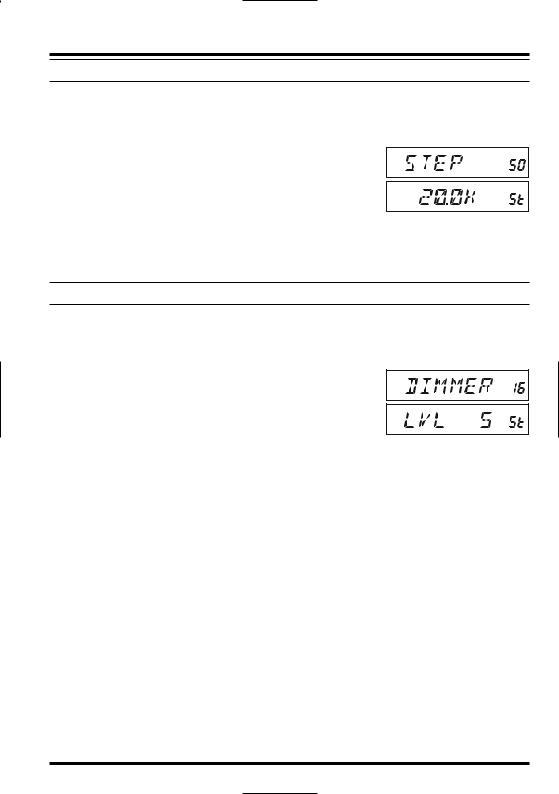
1. Pressandholdinthe[MHz(SET)]keyforonesecond,then rotatetheDIALknobtoselect“50 STEP.”
2. Press the [MHz(SET)] key, then rotate the DIALknob to selectthedesiredstepsize(5/10/12.5/15/20/25/50/100 kHz).
3.Pressandholdinthe[MHz(SET)]keyforonesecondtosaveyournewsettingandexit to normal operation.
DISPLAY BRIGHTNESS
The FT-1900Rdisplay illumination has been specially engineered to provide high visibilitywithminimaldisruptionofyour“nightvision”whileyouaredriving.Thebrightnessof the display is manually adjustable, using the following procedure:
1. Pressandholdinthe[MHz(SET)]keyforonesecond,then rotate the DIALknob to select “16 DIMMER.”
2. Press the [MHz(SET)] key, then rotate the DIALknob to select a comfortable brightness level (LVL 0 - LVL10).
3.Pressandholdinthe[MHz(SET)]keyforonesecondtosaveyournewsettingandexit to normal operation.
FT-1900ROPERATING MANUAL |
19 |

ADVANCED OPERATION
RFSQUELCH
Aspecial RF Squelch feature is provided on this radio. This feature allows you to set the squelch so that only signals exceeding a certain S-meter level will open the squelch.
To set up the RF squelch circuit for operation, use the following procedure:
1. Pressandholdinthe[MHz(SET)]keyforonesecond,then rotate the DIALknob to select “42 RF SQL.”
2. Press the [MHz(SET)] key, then rotate the DIALknob to selectthedesiredsignalstrengthlevelforthesquelchthreshold (S1 - S9 or OFF).
3.Pressandholdinthe[MHz(SET)]keyforonesecondtosaveyournewsettingandexit to normal operation.


 Thereceiver’ssquelchwillopenbasedonthehighestlevelsetbythetwosquelch


 systems, “Noise Squelch” and “RF Squelch.” For example:
1)IftheNoiseSquelch(SQLcontrol)issetsothatsignalsatalevelofS-3willopenthe squelch, but the RF Squelch (Menu #42) is set to “S-9,” the squelch will only open on signals which are S-9 or stronger on the S-meter.
2)IftheRFSquelchissetto“S-3,”buttheNoiseSquelchissettoahighlevelwhichwill only pass signals which are Full Scale on the S-meter, the squelch will only open on signalswhichareFullScaleontheS-meter.Inthiscase,theNoiseSquelchoverridesthe actionof the RF Squelch.
20 |
FT-1900ROPERATING MANUAL |

REPEATER OPERATION
TheFT-1900Rincludesahostofconveniencefeatureswhichmakesoperationonamateur repeaters both efficient and enjoyable.
This transceiver offers three methods of setting up split-frequency operation on repeaters:
Manual selection of preset repeater shifts (Standard Repeater Shift);
Automatic Repeater Shift (ARS), providing automatic activation of repeater shifts while operating within designated repeater frequency subbands; and
Independently stored transmit and receive frequencies (typically not corresponding to established repeater frequency shifts).
STANDARD REPEATER SHIFT
To activate the standard shift manually, you may use the Set (Menu) mode:
1. Pressandholdinthe[MHz(SET)]keyforonesecond,then
rotate the DIALknob to select “43 RPT.” 2. Press the [MHz(SET)] key, then rotate the DIALknob to
select the desired shift direction (–RPT, +RPT, or SIMP).
3.Pressandholdinthe[MHz(SET)]keyforonesecondtosaveyournewsettingandexit to normal operation.


 YoualsomayprogramoneoftheMicrophone’sprogrammablekeys([P1]~[P4])


 toallowquickaccesstotheaboveprocedure.Seepage65fordetailsonthesetup
of the programmable keys.
Withrepeatershiftactivated,youcantemporarilyreversethetransmitandreceivefrequencies by pressing the [REV(DW)] key (or the microphone’s [B] key). Use this feature to displaythetransmitfrequencywithouttransmitting,andtocheckthestrengthofsignalson arepeateruplinkfrequency(soastodeterminewhetherornotaparticularstationiswithin “Simplex” range, for example).
The repeater offset is fixed to 600 kHz from the factory.You can change the offset by the following procedure, if needed for vacation travel or other purposes:
1. Pressandholdinthe[MHz(SET)]keyforonesecond,then rotate the DIALknob to select “46 SHIFT.”
2. Press the [MHz(SET)] key, then rotate the DIALknob to set the desired offset. Note that the resolution of the “standard” repeater shift is to the nearest 50 kHz multiple.
3.Pressandholdinthe[MHz(SET)]keyforonesecondtosaveyournewsettingandexit to normal operation.


 Donotusethisprocedureforprogrammingofan“oddsplit”typerepeaterpair!


 The process for programming odd splits is shown on page 35.
FT-1900ROPERATING MANUAL |
21 |

REPEATER OPERATION
AUTOMATIC REPEATER SHIFT
TheARS(AutomaticRepeaterShift)featureinthistransceiverallowseasyandconvenient repeater operation by automatically activating the repeater shift function whenever you tunetoastandardrepeatersubband.TheARSfunctionispresetatthefactorytoconformto the standards for the country to which it is exported.
TheARS function is enabledat the factory.To disableit:
1. Pressandholdinthe[MHz(SET)]keyforonesecond,then rotate the DIALknob to select “4 ARS.”
2. Press the [MHz(SET)] key, then rotate the DIALknob to change the display to “OFF.”
3.Pressandholdinthe[MHz(SET)]keyforonesecondtosaveyournewsettingandexit to normal operation.
To enable theARS function again, select “ON” in step 2 above.
ARS-Repeater Subbands
VERSION A
145.1 |
145.5 |
146.0 |
146.4 |
147.0 |
147.6 |
148.0 |


 146.6 147.4 145.6 145.8
EUROPEAN VERSION
CHECKING THE REPEATER UPLINK (INPUT)FREQUENCY
Itoftenishelpfultobeabletochecktheuplink(input)frequencyofarepeater,toseeifthe calling station is within direct (“Simplex”) range.
To do this, just press the [REV(DW)] key.You’ll notice that the display has shifted to the repeater uplink frequency. Press the [REV(DW)] key again to cause operation to revert to normalmonitoringoftherepeaterdownlink(output)frequency.Whileyouarelisteningon the input frequency to the repeater using the [REV(DW)] key, the repeater offset icon will blink.
22 |
FT-1900ROPERATING MANUAL |
CTCSS/DCS/EPCSOPERATION
CTCSSOPERATION
Manyrepeatersystemsrequirethatavery-low-frequencyaudiotonebesuperimposedonyour FMcarrierinordertoactivatetherepeater.Thishelpspreventfalseactivationoftherepeaterby radarorspurioussignalsfromothertransmitters.Thistonesystem,called“CTCSS”(Continuous ToneCodedSquelchSystem),isincludedinyourFT-1900R,andisveryeasytoactivate.


 CTCSSsetupinvolvestwoactions:settingtheToneModeandthensettingofthe


 Tone Frequency. These actions are set up by using the Set (Menu) mode, selec-
tions #49 (SQL.TYP) and #52 (TN FRQ).
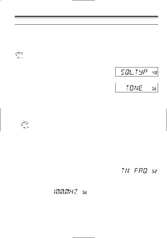
1. Pressandholdinthe[MHz(SET)]keyforonesecond,then
rotatetheDIALknob to select “49 SQL.TYP.”
2.Press the [MHz(SET)] key, then rotate the DIALknob so that “TONE” appears on the display; this activates the CTCSS Encoder, which allows 
repeater access.
3.RotatingtheDIALknobonemoreclickclockwiseintheabovestepwillcause“TSQL” to appear. When “TSQL” appears, this means that the Tone Squelch system is active, whichmutesyourFT-1900R’sreceiveruntilitreceivesacallfromanotherradiosend- ingoutamatchingCTCSStone.Thiscanhelpkeepyourradioquietuntilaspecificcall is received, which may be helpful while operating in congested areas.


 1)You may notice a “RV TN” indication on the display while you rotate the


 DIALknob in this step; this means that the Reverse Tone Squelch system is active,whichmutesyourFT-1900R’sreceiver(insteadofopeningthesquelch)when itreceivesacallfromtheradiosendingamatchedCTCSStone.The“T SQ”iconwill blink on the display when the Reverse Tone Squelch system is activated.
2)Youmaynoticea“DCS”indicationonthedisplaywhileyourotatetheDIALknob stillmore.We’lldiscusstheDigitalCodeSquelchsystem shortly.
4.When you have made your selection of the CTCSS tone mode, press the [MHz(SET)] keymomentarily,thenrotatetheDIALknobthreeclicksclockwisetoselectMenu“52
|
TN FRQ.”ThisMenuselectionallowssettingoftheCTCSS |
|
|
|
|
|
|
|||||
|
tone frequency to be used. |
|
|
|
|
|
|
|
|
|
||
5. |
Pressthe[MHz(SET)]keytoenableadjust- |
|
|
|
|
|
|
|
|
|
||
|
CTCSSTONEFREQUENCY(Hz) |
|
||||||||||
|
ment of the CTCSS frequency. |
67.0 |
|
69.3 |
71.9 |
74.4 |
77.0 |
|
79.7 |
|||
|
|
|
|
|
|
|
|
|
|
|
|
|
|
|
|
|
|
|
|
|
|
|
|
||
6. |
Rotate the |
|
|
82.5 |
|
85.4 |
88.5 |
91.5 |
94.8 |
|
97.4 |
|
|
DIAL knob |
|
|
100.0 |
|
103.5 |
107.2 |
110.9 |
114.8 |
|
118.8 |
|
|
|
|
|
123.0 |
|
127.3 |
131.8 |
136.5 |
141.3 |
|
146.2 |
|
|
until the display indicates the Tone Fre- |
|
|
|||||||||
|
151.4 |
|
156.7 |
159.8 |
162.2 |
165.5 |
|
167.9 |
||||
|
quency you need to be using. |
|
|
|||||||||
|
|
|
|
|
|
|
|
|
|
|||
|
171.3 |
|
173.8 |
177.3 |
179.9 |
183.5 |
|
186.2 |
||||
7. |
When you have made your selection, press |
|
|
|||||||||
189.9 |
|
192.8 |
196.6 |
199.5 |
203.5 |
|
206.5 |
|||||
|
and hold in the [MHz(SET)] key for one |
210.7 |
|
218.1 |
225.7 |
229.1 |
233.6 |
|
241.8 |
|||
|
second to save the new setting and exit to |
|
|
|
|
|
|
|
|
|
||
|
250.3 |
|
254.1 |
|
– |
– |
– |
|
– |
|||
|
normal operation. |
|
|
|
|
|
|
|
|
|
||
|
|
|
|
|
|
|
|
|
|
|
|
|
FT-1900ROPERATING MANUAL |
23 |
 Loading...