

Page 1
INSTRUCTION MANUAL
P81630
REVISION E
INSTALLER: PLEASE LEAVE THIS MANUAL FOR THE OWNER’S USE.
Series VSC® and VSCS®
Base Mounted
Centrifugal Pumps
(TO BE USED IN CONJUNCTION WITH VSC PARTS LIST CONTAINING LINE DRAWINGS)
Page 2
DESCRIPTION
WARNING
ROTATING COMPONENTS
DISCONNECT AND LOCK OUT
POWER BEFORE SERVICING.
DO NOT OPERATE WITHOUT
ALL GUARDS IN PLACE.
CONSULT INSTALLATION
AND SERVICE INSTRUCTION
SHEET BEFORE OPERATING
OR SERVICING.
FAILURE TO FOLLOW
INSTRUCTIONS COULD
RESULT IN INJURY
OR DEATH.
P70642
WARNING
EYEBOLTS OR LIFTING
LUGS IF PROVIDED ARE
FOR LIFTING ONLY THE
COMPONENTS TO WHICH
THEY ARE ATTACHED.
FAILURE TO FOLLOW
INSTRUCTIONS COULD
RESULT IN INJURY
OR DEATH.
P70643
CAUTION
DO NOT RUN PUMP DRY,
SEAL DAMAGE MAY OCCUR.
INSPECT PUMP SEAL
REGULARLY FOR LEAKS,
REPLACE AS REQUIRED.
FOR LUBRICATION
REQUIREMENTS, CONSULT
SERVICE INSTRUCTIONS.
FAILURE TO FOLLOW
INSTRUCTIONS COULD
RESULT IN INJURY OR
PROPERTY DAMAGE.
P70644
CAUTION
COUPLER ALIGNMENT IS
REQUIRED! LEVEL AND GROUT
PUMP BEFORE USE!
CHECK ALIGNMENT BEFORE
GROUTING, AFTER SYSTEM IS
FILLED, AFTER SERVICING
PUMP, AND AS REQUIRED.
CONSULT THE SERVICE
INSTRUCTIONS FOR DETAILS.
FAILURE TO FOLLOW THESE
INSTRUCTIONS COULD
RESULT IN INJURY OR
PROPERTY DAMAGE.
P70820
The VSC and VSCS Series centrifugal pumps are frame mounted
pumps which feature – high efficiency, rugged construction,
compact design, foot mounted volute, center drop out coupler,
and regreasable bearings. These features along with the vertically split case make installation, operation, and service easy to
perform.
OPERATIONAL LIMITS
Unless special provisions have been made for your pump by
Bell & Gossett, the operational limits for VSC/VSCS Series
Pumps are as follows:
Maximum Working Pressur
Listed on pump nameplate.
SEAL OPERATING LIMITS
Standard Seals
BUNA-PH Limitations 7-9; Temperature Range -40 to +225°F
EPT-PH Limitations 7-11; Temperature Range -40 to +250°F
For use on closed or open systems which are relatively free of
dirt and/or other abrasive particles.
Flushed Single Seals
PH Limitations 7-9; Temperature Range 0 to +250°F†
Note: On closed or open low pressure systems which may
contain a high concentration of abrasives an external flush is
required.
e
PUMP APPLICATION
The standard VSC and VSCS Series centrifugal pump’s br
fitted construction make it ideal for service with the following
liquids: unheated domestic and fresh water, boiler feed water
condensate, hydronic cooling or heating, pressure boosting,
general pumping and benign liquids.
For other applications contact your local B&G Representative.
Flushed Double Seals
PH Limitations 7-9; Temperature Range 0 to +250°F
Note: On closed or open low pressure systems which may
contain a high concentration of abrasives an external flush is
required.
Packing
PH Limitations 7-9; Temperatur
e Range 0 to +200°F
Note: On open or closed systems which require a large
amount of makeup water, as well as systems which are subjected to widely varying chemical conditions and solids buildup.
† For operating temperatures above 250°F a cooled flush is requir
and is recommended for temperatures above 225°F for optimum seal
life. On closed systems cooling is accomplished by inserting a small
heat exchanger in the flush line to cool the seal flushing fluid.
Flush-line Filters and Sediment Separators are available on special
request.
onze
ed
,
This safety alert symbol will be used in this manual and on the
pump safety Instruction decal to draw attention to safety related
instructions. When used, the safety alert symbol means
ATTENTION! BECOME ALERT! YOUR SAFETY IS INVOLVED!
FAILURE TO FOLLOW THE INSTRUCTIONS MAY RESULT IN
A SAFETY HAZARD.
Your VSC/VSCS Series Pump should have the following safety
instruction decals located approximately as shown. If the
decals are missing or illegible contact your local B&G representative for a replacement.
2
SAFETY
INSTRUCTION
ALTERNATE
LOCATION
(2) REQUIRED
(1 EACH SIDE)
Page 3
ADDITIONAL SAFETY REQUIREMENTS:
ELECTRICAL SAFETY:
MECHANICAL SAFETY:
WARNING: Electrical Shock Hazard
Electrical connections to be made by a qualified
electrician in accordance with all applicable codes, ordinances, and good practices. Failure to follow these instructions could result in serious personal injury or death,
or property damage.
WARNING: Electrical Overload Hazard
Three phase motors must have properly sized
heaters to provide overload and undervoltage protection.
Single phase motors have built-in overload protectors.
Failure to follow these instructions could result in serious
personal injury or death, or property damage.
THERMAL SAFETY:
WARNING: Extreme Temperature Hazard
If pump, motor, or piping are operating at extremely
high or low temperatures, guarding or insulation is required. Failure to follow these instructions could result in
serious personal injury or death, or pr
operty damage.
PUMP LOCATION
Locate the pump so there is sufficient room for inspection, maintenance and service. If the use of a hoist or tackle is needed,
allow ample head room.
WARNING: Unexpected Startup Hazard
Disconnect and lockout power before servicing.
Failure to follow these instructions could result in serious
personal injury or death, or property damage.
W
ARNING: Excessive System Pressure Hazard
The maximum working pressure of the pump is listed
on the nameplate, do not exceed this pressure. Failure to
follow these instructions could r
esult in serious personal
injury or death, or property damage.
WARNING: Excessive Pr
essure Hazard
Volumetric Expansion
The heating of water and other fluids causes volumetric
expansion. The associated forces may cause failur
e of system components and release of high temperature fluids.
This will be prevented by installing properly sized and
located compression tanks and pressure relief valves.
Failure to follow these instructions could result in serious
personal injury or death, or property damage.
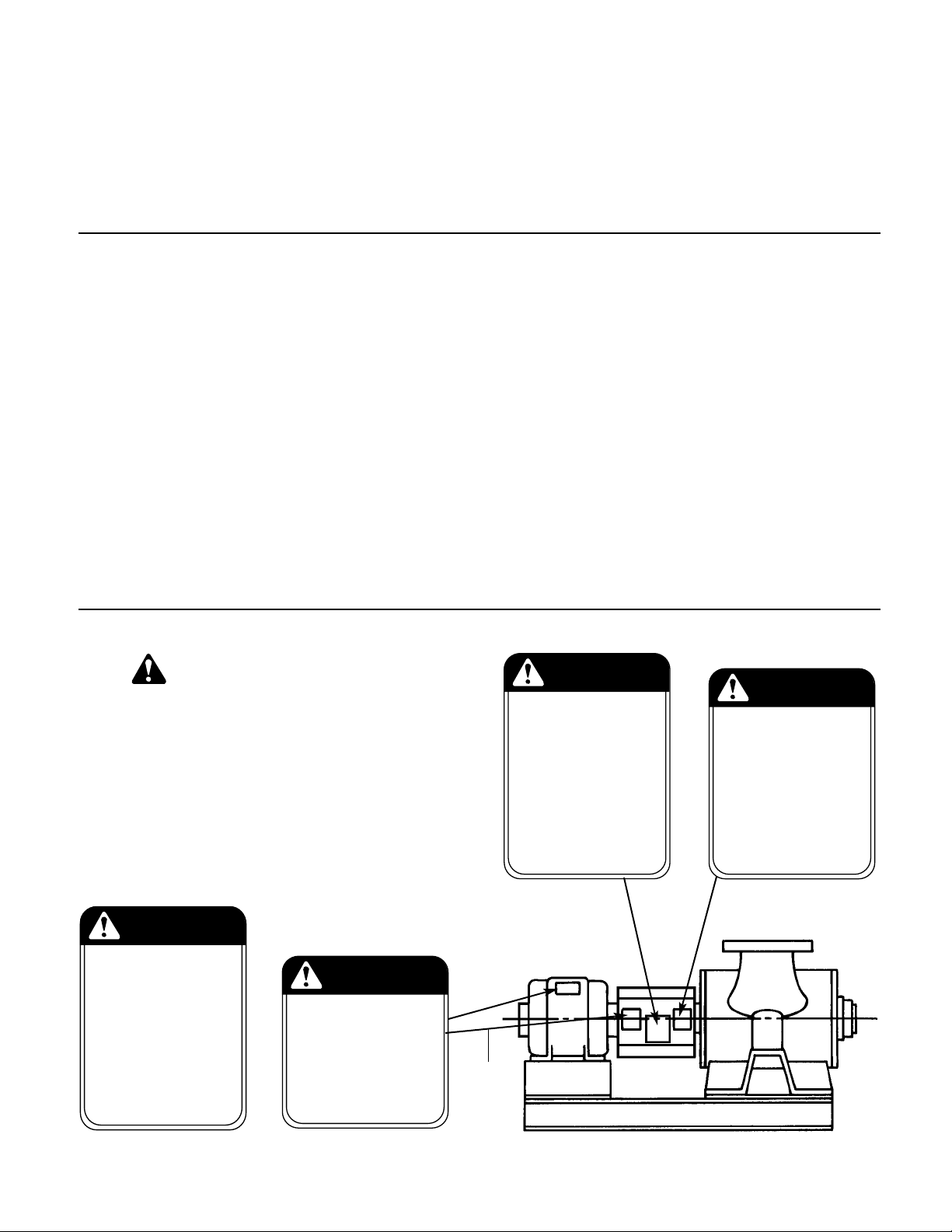
WARNING: Fall Objects Hazard
Eyebolts or lifting lugs, if provided, are for lifting only
the components to which they are attached. Failure to follow these instructions could result in serious personal
injury or death, or property damage.
If lifting of the entire pump is required, do so with slings placed
under the base rails as shown.
The best pump location for sound and vibration absorption is
on a concrete floor with subsoil underneath. If the pump location is overhead, special precautions should be undertaken to
reduce possible sound transmission, consult a sound specialist.
If the pump is not on a closed system, it should be placed as
near as possible to the source of the liquid supply, and located
to permit installation with the fewest number of bends or
elbows in the suction pipe.
COMPRESSION TANK
SHOULD BE LOCATED
ON THE SUCTION SIDE
OF THE PUMP
B&G REDUCING
VALVE
COLD
WATER
SUPPLY
FROM BOILER
CHILLER OR CONVER
TER
B&G ROLAIRTROL
AIR SEPARATOR
ISOLATION
VALVE
SUPPLY
TO SYSTEM
B&G CIRCUIT
SETTER
B&G TRIPLE DUTY
VALVE
The installation must be evaluated to determine that the Net
Positive Suction Head Available (NPSHA) meets or exceeds the
Net Positive Suction Head Required (NPSHR), as stated by the
pump performance curve.
IMPORTANT
Do not install and operate Bell & Gossett Pumps, 3D Valves,
Suction Diffusers, etc., in closed systems unless the system is
constructed with properly sized safety devices and control
devices. Such devices include the use of properly sized and
located pressure relief valves, compression tanks, pressure controls, temperature controls, and flow controls as appropriate. If
the system does not include these devices, consult the responsible engineer or architect before making pumps operational.
3
Page 4
INSTALLATION
This pump is built to provide years of service if installed properly
and attached to a suitable foundation. A base of concrete weighing 21/2 times the weight of the pump is r
the shipping ticket for pump weight.)
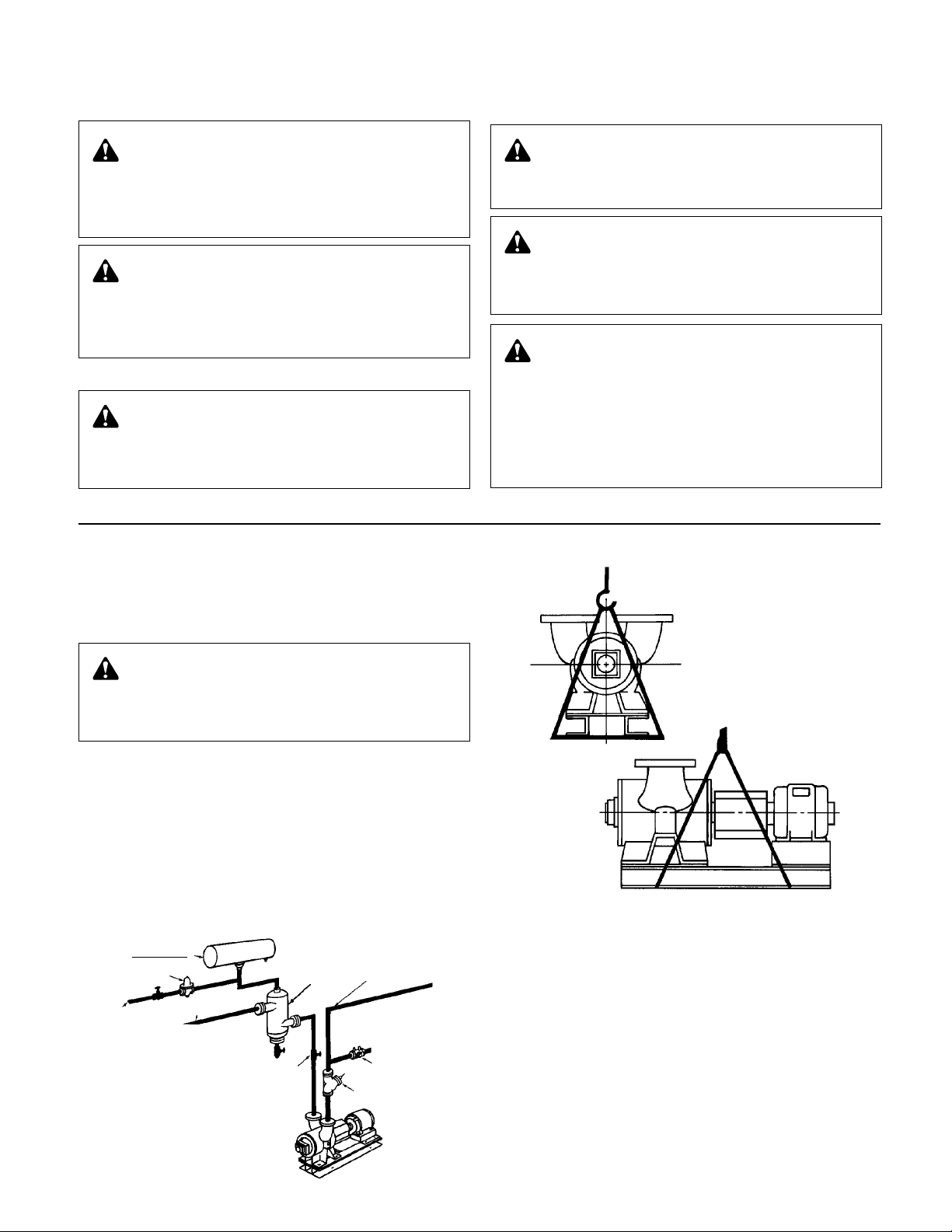
If possible, tie the concrete pad in with the finished floor. Use
foundation bolts and larger pipe-sleeves to give room for final
bolt location. (See Figure 6A.)
ecommended. (Check
PIPE
SLEEVE
FOUNDATION
BOLT
LEVELING
Place the pump on its concrete foundation supporting it with
steel wedges or shims totaling 1" in thickness. These wedges
or shims should be put on both sides of each anchor-bolt to
provide a means of leveling the base. (See Figure 6B.)
It is very important that the pump-base be set level to avoid any
mechanical difficulties with the motor or pump. This pump was
properly aligned (if furnished with a motor) at the factory
. However, since all pump bases are flexible they may spring and twist
during shipment. Don’t pipe the pump until it is realigned. After
piping is completed and after the pump is grouted-in and bolteddown, align it again. It may be necessary to re-adjust the alignment from time to time while the unit and foundation are new.
GROUTING
After the pump has been leveled, securely bolted to the floor,
and properly aligned, a good grade of non-shrinking grout
should be poured inside the pump base. To hold wedges or
shims in place, allow the grout to flow around them.
ROTATION
The VSC & VSCS pump is available in both right- and left-hand
rotation. An arrow cast into the pump body shows the direction
of rotation.
BUILT-UP
CONCRETE FOUNDATION
ALLOW 1" FOR SHIMS.
PLACE ON BOTH SIDES
OF ANCHOR BOLTS.
APPROX.
GAP
1"
LEVELING OF PUMP BASE
ON CONCRETE FOUNDATION.
WASHER
NOTE:
TO KEEP SHIMS IN
PLACE ALLOW GROUT
TO FLOW AROUND
HOLD DOWN LUGS.
GROUT
CONCRETE
FOUNDATION
FIGURE 6A
GROUT ONLY TO
TOP OF BASE RAIL.
PUMP
BASE RAIL
FIGURE 6B
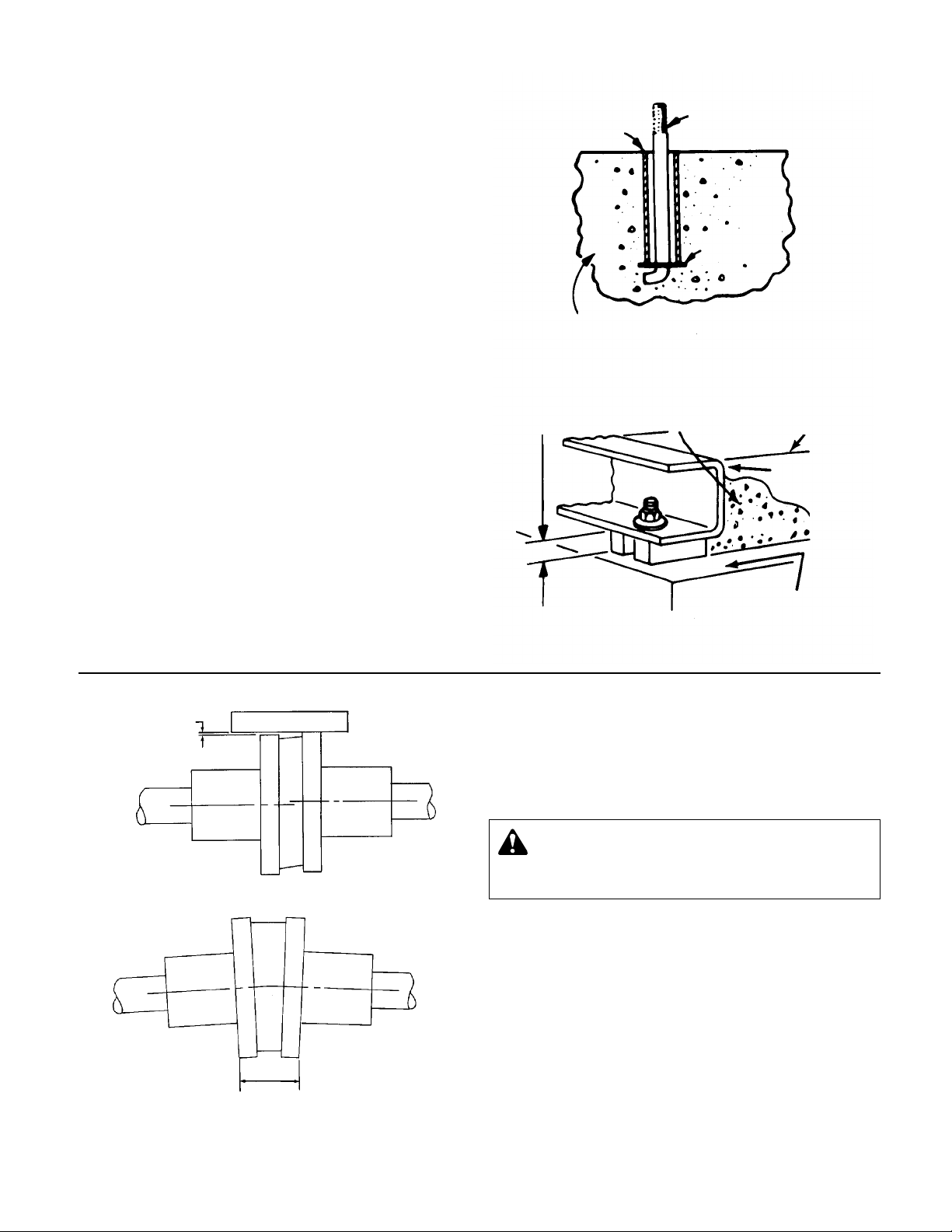
AMOUNT OF
PARALLEL
MISALIGNMENT
STRAIGHT EDGE
PARALLEL ALIGNMENT CHECK
DISTANCES ACROSS
COUPLER FLANGES
SHOULD BE EQUAL
(CHECK 4 PLACES)
ANGULAR ALIGNMENT CHECK
COUPLER ALIGNMENT
All alignment should be done by moving or shimming the motor
only. Adjustments in one direction may alter alignment in another.
Therefore, check alignment in all directions after a correction is
made. Black rubber inserts have different horsepower load
ratings than orange Hytrel sleeves. They should not be
interchanged.
WARNING: Unexpected Startup Hazard
Disconnect and lockout power before servicing.
Failure to follow these instructions could result in serious
personal injury or death, or property damage.
STANDARD SLEEVE TYPE COUPLER
WITH BLACK RUBBER INSERT
Before aligning the coupler, make sure there is about 1/8" end
clearance between the sleeve and the two coupler halves.
1. Check angular misalignment using a micrometer or caliper.
Measure from the outside of one flange to the outside of the
opposite flange at four points 90° apart. DO NOT ROTATE
COUPLER. Misalignment up to 1/64" per inch of coupler
radius is permissible.
2. At four points 90° apart (DO NOT ROTATE COUPLER), measure the parallel coupler misalignment by laying a straight
edge across one coupler half and measuring the gap
between the straight edge and opposite coupler half. Up to a
1
/64" gap is permissible.
4
Page 5
FOR FINE ALIGNMENT, ORANGE HYTREL INSERTS,
3500 RPM OPERATION, OR ALL OTHER COUPLER TYPES
Use a dial indicator when greater alignment accuracy is required. Use the following alignment tolerances unless specified
otherwise by the coupler manufacturer. On sleeve type couplers
make sure there is about 1/8" end clearance between the sleeve
and the two coupler halves.
1. To check angular misalignment, mount the dial indicator
base to one coupler half, or shaft, and position the dial indicator button on the front or rear face of the opposite coupler
half. Set the dial to zero. Rotate both coupler halves together,
making sure the indicator button always indicates off the
same spot. Misalignment values within 0.004" TIR per inch of
coupler radius are permissible.
2. To check parallel misalignment, mount the dial indicator base
to one coupler half, of shaft, and position the dial indicator
button on the outside diameter of the opposite coupler half.
Set the dial to zero. Rotate both coupler halves together,
making sure the indicator button always indicates off the
same spot. Misalignment within 0.004" TIR is permissible.
PIPING
Always install a section of straight pipe between the suction
side of the pump and first elbow. This reduces turbulence of
the suction by straightening out the flow of liquid before it
enters the pump. The length should be equal to five times the
diameter of the suction pipe size.
Line up the piping so that the bolt-holes in the pump flanges
match the bolt-holes in the pipe flanges. DO NOT ATTEMPT
TO SPRING THE SUCTION OR DISCHARGE LINES INTO
POSITION. Coupling and bearing wear will result if suction or
discharge lines are forced into position. The code for Pressure
Piping (ANSI B.31.1) lists many types of supports available for
various applications.
When considerable temperature changes are anticipated,
equipment for absorbing expansion should be installed in the
system in such a way as to avoid strain on the pump.
When using an isolation base, flexible piping should also be
used on both suction and discharge sides of pump.
On an open-system with a suction-lift, use a foot-valve of equal
of greater area than the pump suction piping. Prevent clogging
by using a strainer at the suction inlet next to the foot-valve.
The strainer should have an area three times that of the suction
pipe with hole diameter of no less than 1/4".
The pipeline should have isolation valves around the pump and
have a drain valve in the suction pipe.
A Bell & Gossett Triple Duty Valve installed in the discharge line
will serve as a check valve to protect the pump from water
hammer, as a gate valve for servicing and for throttling.
PUMP INSULATION
When insulating a Series VSC/VSCS pump, ensure that the
grease fittings remain accessible and visible. Do not seal off the
drain holes in the bearing caps or bearing housings.
PRIMING AND STARTING
CAUTION: Seal Damage Hazard
Do not run pump dry, seal damage may occur.
Failure to follow these instructions could result in serious
property damage and/or moderate personal injury.
Before starting the pump, the pump body must be full of liquid.
Manual priming may be required if the system does not automatically fill the pump body with liquid. Vent plugs are provided
on the pump body to vent the air. While venting the air from the
pump body the pump shaft should be rotated a few times by
hand.
The pump should be started with the discharge valve closed
and the suction valve fully open. After the pump is up to operating speed the discharge valve should be opened slowly.
IMPORTANT: The pump should never be operated with the
suction valve closed or throttled. This could result in cavitation.
LUBRICATION
Lubricate pump bearings at least twice a year or flush bearings
whenever necessary with NLGI Grade No. 2 mineral base or
lithium base petroleum grease while the pump is running. On
chilled water applications it is important to keep the bearing
cavity full of grease to protect from condensation. Lubricate
motor bearings in accordance with the manufacturer’s instructions.
GENERAL INSTRUCTIONS
1. Keep this pump and motor properly lubricated.
2. Protect the motor against overload and low-voltage. Use a
motor-starter with proper size heater elements.
3. When there is danger of freezing, remove the plugs at the top
and bottom of the volute shell.
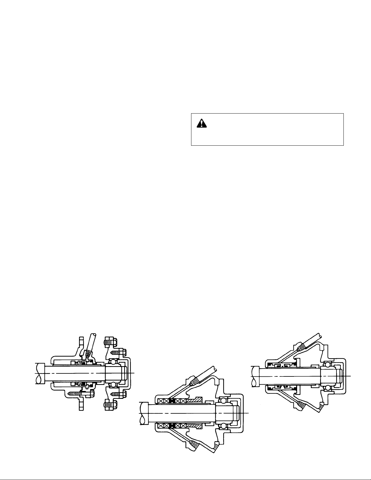
VSCS-S
VSCS-D
VSCS-PF
5
Page 6

COVERPLATE
CAPSCREWS
COVERPLATE
BEARING
HOUSING
CAPSCREW
BEARING
COVER
CAPSCREW
BEARING
COVER
BEARING
VOLUTE
IMPELLER
SEAL
SLINGER
SHAFT
STANDARD SEAL CONFIGURATION
COVERPLATE
CAPSCREW
COVERPLATE
BEARING
HOUSING
CAPSCREW
BEARING
COVER
BEARING
SHAFT
SLINGER
SEAL
IMPELLER
VOLUTE
SERVICE INSTRUCTIONS
(Follow these first three steps for all VSC(S) pumps, then proceed to the pump size and model that corresponds to the size
and model on the pump nameplate).
WARNING: Unexpected Startup Hazard
Disconnect and lockout power before servicing.
Failure to follow these instructions could result in serious
personal injury or death, or property damage.
1. Close valves on suction and discharge sides of pump. If
no valves have been installed, it will be necessary to drain
the system.
2. Remove the coupler guard. Refer to section titled “Hex
Coupler Guard Removal/Installation.” 3. Loosen the capscrews which secure the coupler flanges to
6
CAUTION: Extreme Temperature Hazard
Allow pump temperatures to reach acceptable levels
before proceeding. Open drain valve, do not proceed until
liquid stops coming out of drain valve. If liquid does not
stop flowing from drain valve, isolation valves are not sealing and should be repaired before proceeding. After liquid
stops flowing from drain valve, leave valve open and continue. Remove the drain plug located on the bottom of the
pump housing. Do not reinstall plug or close drain valve
until reassembly is completed. Failure to follow these
instructions could result in property damage and/or moderate personal injury.
the coupler hubs. Remove the coupler flanges and sleeve
by compressing the flanges and pulling out from beneath
the hubs or by loosening the allen set screws and sliding
the hubs back on the shafts. Remove the coupler hub from
the pump shaft.
Page 7

INSTRUCTIONS FOR CHANGING DIRECTION OF ROTATION FOR VSC AND VSCS PUMPS
1. Remove coupler guard and coupler
.
2. Remove both bearing caps and bearing lock nuts.
3. Remove both bearing housings together with bearing.
4. Remove outboard cover plate.
5. Remove shaft and impeller assembly.
6. Remove impeller nut and pull (press fitted) impeller from
shaft. Observe direction that vane tips are pointing. Turn
impeller end for end (180°) and press back onto shaft.The
vane tips should be pointing in the opposite direction.
7. Remove volute from base. Remove inboard cover plate
from volute.*
8. Reassemble cover plate, which was removed from outboard side, by placing on same side of volute. Turn volute
end for end (180°) and mount back on base. The cover
plate that was located on the outboard side of the pump,
should now be on the inboard (motor) side of the pump.
9. Insert shaft assembly, with r
eversed impeller, back into
pump casing and reassemble second cover plate (now
outboard) to volute.
10. Reassemble seals, bearing housings, bearing and bearing
caps. (Bearings and housings are identical side to side.)
11. Reassemble coupler and reattach guard.
In summary, the impeller, volute and cover plates should all
have been reversed end for end. The orientation of the remaining parts should not have changed.
*It is important to remember that in the order to keep the water passages open, the cover plates must be reassembled to the same side
of the volute from which they were removed. In effect, they should be
rotated along with the volute. In fact, the inboard cover plate does not
need to be removed, if the complete pump end is reassembled before
being mounted on the base.
SERVICE INSTRUCTIONS FOR PUMPS WITH A STANDARD MECHANICAL SEAL (VSC-VSCS)
TO REPLACE THE SEALS:
4. Remove the bearing cover capscrews. To release the bearing cam lock, loosen the allen set screw and tap the cam
lock counter-clockwise with a drift pin.
5. Remove two capscrews and loosen the remaining capscrews that hold the bearing housing to the volute coverplate.
WARNING: Excessive Pressure Hazard
Make certain internal pressure is relieved before continuing. Failure to follow these instructions could result in
serious personal injury or death, or property damage.
Remove the bearing housing by placing two capscrews in
the jackscrew holes provided.
6. Remove the bearing from the bearing housing by gently
tapping the bearing’s inner race. NOTE: If the water slinger
has fallen into the bearing housing, be sure to remove and
replace with the one provided (see Figure 1). Take care to
avoid damage to the ceramic seal insert.
7. Remove the ceramic insert from housing by tapping from
the rear.
8. Using 2 screwdrivers, pull the rotating seal assembly from
the pump shaft (see Figure 2). Clean and inspect the shaft
and bearing housing for damage, replace if required.
IMPORTANT: When working on the seal on the noncoupler end, it is necessary to force the pump shaft back
from the coupler end as far as possible and to hold it in
this position while installing and locking the bearing to the
shaft. Also, when replacing both seals, the seal on the
non-coupler end of the pump should be installed first.
9. Lubricate the seal assemblies and insert cups with soapy
water, and then place the rotating seal assemblies on the
shaft and the ceramic inserts and cups into each of the
bearing housings, make certain inserts bottom against
bores. Install the bearing housing gaskets and the bearing
housings on the pump.
10. Slide the water slingers on the shaft and over the shoulder
so as not to interfere with the bearings. Clean and regrease bearings and insert into bearing housings. Push the
pump shaft back from the motor end as far as possible,
using a lever if necessary. Hold the shaft in this position.
Tap on the outboard bearing inner race until it is properly
positioned against the shaft shoulder. Install and lock the
cam lock into position. If the shaft and bearing are properly
positioned, the cam lock set screw will fall in the center of
the shaft undercut. Release the shaft. Install the outboard
bearing cap. Install the inboard bearing by tapping the
inner race until it contacts the shaft shoulder, lock the bearing in place with the cam lock. Install the inboard bearing cap.
11. Replace drain plug.
12. Install coupler and align, following the instructions located in
the “Coupler Alignment” section.
13. Install coupler guard. Refer to separate instructions titled
“Hex Coupler Guard Removal/Installation.”
14. Open isolation valves and check pump for leaks. If not
leaking, return pump to service.
FIGURE 1
FIGURE 2
7
Page 8

“O” RING*
SHAFT SLEEVE
SEAL COLLAR
SET SCREWS
ROTATING
SEAL MEMBERS
GASKET
SEAL CARBON
SEAL HOUSING
1
/16"
REF.
ASSEMBLY AID
DRIVE COLLAR
DRIVE COLLAR
SET SCREWS,
CUP POINT
PUMP SHAFT
COMPRESSION TO 1/4"
*NOTE: On earlier models this groove is cut into the shaft sleeve.
SHAFT SLEEVE
SET SCREWS,
DOG POINT
SERVICE INSTRUCTIONS FOR PUMPS WITH A SINGLE FLUSH MECHANICAL SEAL (VSC-S, VSCS-S)
(See special instructions for pumps 10 x 12 x 17, 12 x 14 x 121/2, 12 x 14 x 171/2 and 8 x 10 x 17)
TO REPLACE THE SEALS OR SHAFT SLEEVES:
4.
Remove bearing cover and release bearing cam lock.
5.
Remove bearing housing capscrews. Pull housing and
bearing from the pump shaft using capscrews in jackscrew holes.
WARNING: Excessive Pressure Hazard
Make certain internal pressure is relieved before con
tinuing. Failure to follow these instructions could result in
serious personal injury or death, or property damage.
6. Remove flushing tube and capscrews from seal housing.
7. Remove outer two set screws in shaft sleeve drive collar.
Loosen two inner set scr
8.
Remove the drive collar, seal housing, rotating seal assem-
ews one turn.
bly and sleeve.
9. To assemble the pump, clean shaft sleeve and pump shaft.
Replace shaft sleeve if pitted or scored. If replacing the
seal, remove shaft O-ring and replace (included in seal kit).
10. Lubricate O-ring on stationary seal seat (carbon) with silicone grease or soapy water. DO NOT USE PETROLEUM
LUBRICANT! Position in seal housing.
11. Place shaft sleeve in drive collar and tighten the two dog
point set screws in holes provided.
12. Set shaft sleeve and drive collar assembly on end and
place assembly aid spacer around the shaft sleeve.
Position against drive collar.
13. Place seal housing with carbon over the end of the sleeve
against assembly aid spacer.
14.
Lubricate O-ring in rotating seal assembly with silicone
grease or soapy water. DO NOT USE PETROLEUM
LUBRICANT! Slip rotating seal assembly on the end of the
sleeve and place against carbon.
15.
Compress rotating seal assembly to a
1
/
4" space between
the seal parts that house the compression springs. Tighten
set screws.
16. Apply anti-seize compound only to the area of the shaft
that will be under the sleeve. Place seal housing gasket in
position and slide complete assembly over pump shaft.
IMPORTANT! When working on the seal on the noncoupler end, it is necessary to force the pump shaft back
fr
om the coupler end as far as possible and to hold it in
this position while installing and locking the bearing to the
shaft. Also, when replacing both seals, the seal on the
non-coupler end of the pump should be installed first.
17.
Install the bearing housings. Clean and regrease the bearings and insert into bearing housings. Push the pump shaft
back from the motor end as far as possible, using a lever if
necessary. Hold the shaft in this position. On the outboard
bearing tap inner race until it is properly positioned against
the shaft shoulder. Install and lock the cam lock into position. If the shaft and bearing are properly positioned, the
cam lock set screw will fall in the center of the shaft undercut. Release the shaft. Install the outboard bearing cap.
Install the inboard bearing by tapping the inner race until it
contacts the shaft shoulder, lock the bearing in place with
the cam lock. Install the inboard bearing cap.
18. Push on the drive collar until the seal housing is against
the stuffing box bracket, bolt into place.
19. Tighten down collar set screws in undercut of shaft.
Remove assembly aid spacer and connect flush tubing to
seal housing.
20. Replace drain plug.
21. Install coupler and align, following the instructions located in
the section titled “Coupler Alignment.”
22. Install coupler guard. Refer to separate instructions titled
“Hex Coupler Guard Removal/Installation.”
23. Open isolation valves and check pump for leaks. If not
leaking, return pump to service.
SERVICE INSTRUCTIONS FOR PUMPS WITH A DOUBLE FLUSH MECHANICAL SEAL (VSC-D, VSCS-D)
(See special instructions for pumps 10 x 12 x 17, 12 x 14 x 121/2, 12 x 14 x 171/2 and 8 x 10 x 17)
TO REPLACE THE SEAL OR SHAFT SLEEVE:
4. Remove bearing cover and release bearing cam lock.
5. Remove bearing housing capscrews. Pull housing and
bearing from shaft using capscrews in jackscrew holes.
6. Remove flush tube and capscrews from seal housing.
7. Remove outer two screws in shaft sleeve drive collar.
WARNING: Excessive Pressure Hazard
Make certain internal pressure is relieved before continuing. Failure to follow these instructions could result in
serious personal injury or death, or property damage.
8
8. Remove stuffing box bracket capscrews and pull entire
stuffing box assembly from the volute coverplate.
9. Remove the seal cap and seal assembly from the stuffing
box.
10. If replacing the shaft sleeve, remove the sleeve and
replace. Inspect all parts to be re-used and replace if damaged.
11. Lubricate stationary O-ring with silicone grease or soapy
water. DO NOT USE PETROLEUM LUBRICANT! Insert
O-ring toward impeller. Place one seal carbon into the bottom of the stuffing box and carefully install in position.
12. Lubricate the O-rings of the rotating seal member and
position on sleeve against the seal carbon.
Page 9

13. Install the second seal carbon. Lubricate and insert
second stationary O-ring toward cap. Replace seal cap.
14. Apply anti-seize compound only to the shaft that will be
under the sleeve.
15. Place the stuffing box gasket onto the bracket and install
assembly into the coverplate. Position sleeve drive collar
outer holes over undercut in shaft and tighten set screws.
Install the bearing housings.
IMPORTANT! When working on the seal on the noncoupler end, it is necessary to force the pump shaft back
from the coupler end as far as possible and to hold it in
this position while installing and locking the bearing to the
shaft. Also, when replacing both seals, the seal on the
non-coupler end of the pump should be installed first.
16. Clean and regrease the bearings and insert into bearing
housings. Push the pump shaft back from the motor end as
far as possible, using a lever if necessary. Hold the shaft in
this position. On the outboard bearing tap inner race until it
is properly positioned against the shaft shoulder. Install
and lock the cam lock into position. If the shaft and bearing are properly positioned, the cam lock set scr
in the center of the shaft undercut. Release the shaft.
Install the outboard bearing cap. Install the inboard bearing by tapping the inner race until it contacts the shaft
shoulder, lock the bearing in place with the cam lock.
Install the inboard bearing cap.
17. Replace drain plug.
18. Install coupler and align per instructions located in the
section titled “Coupler Alignment.”
19. Install coupler guard. Refer to separate instructions titled
“Hex Coupler Guard Removal/Installation.”
20. Open isolation valves and check pumps for leaks. If not
leaking, return pump to service.
NOTE: Flushing pressure must be the suction pressure on
the pump plus 10 PSI.
SPECIAL INSTRUCTIONS FOR PUMPS (VSCS, VSC-S & VSCS-D)
10 x 12 x 17, 12 x 14 x 121/2 and 12 x 14 x 171/2
TO REPLACE THE SEAL OR SHAFT SLEEVE:
WARNING: Excessive Pressure Hazard
Make certain internal pressure is relieved before continuing. Failure to follow these instructions could result in
serious personal injury or death, or property damage.
ew will fall
4. Remove flush tube and tube fitting from seal housing
inside bearing bracket.
5. Remove bearing bracket capscrews and bearing cover
capscrews inside the bracket.
6. Remove bearing bracket using capscrews in jackscrew
holes. DO NOT PULL BEARING COVER.
7. Remove bearing locknut by straightening tab of lockwasher
from notch in locknut and turning locknut counterclockwise.
8. Remove lockwasher and pull bearing from shaft.
9. Remove retainer ring from shaft, except on 12 x 14 x 171/2.
10. Now remove bearing cover.
11. Remove capscrews from seal housing. Remove outer two
set screws from shaft sleeve drive collar and loosen two
inner set screws one turn.
12. Remove the sleeve and seal assembly from the shaft by
pulling on the seal housing.
13. To assemble the pump, clean shaft sleeve and pump shaft.
Replace shaft sleeve if pitted or scored. If replacing the
seal, remove shaft O-ring and replace (included in seal kit).
NOTE: If installing -D seals refer to steps 10-12 on -D
instructions then skip to 17.
14. Lubricate O-ring on stationary seal seat (carbon) with silicone grease or soapy water. DO NOT USE PETROLEUM
LUBRICANT! Position in seal housing. Place shaft sleeve
in drive collar and tighten the two dog point set screws in
holes provided. Set shaft sleeve and drive collar assembly
on end and place assembly aid spacer around shaft
sleeve. Position against drive collar.
15. Place seal housing with carbon over the end of the sleeve
against assembly aid spacer.
16. Lubricate O-ring in rotating seal assembly with silicone
grease or soapy water. DO NOT USE PETROLEUM
LUBRICANT! Slip rotating seal assembly on the end of the
sleeve and place against carbon.
17. Compress rotating seal assembly to a 1/4" space between
the seal parts that house the compression springs. Tighten
set screws.
18. Apply anti-seize compound only to the area of the shaft
that will be under the sleeve. Place seal housing gasket in
position and slide complete assembly over pump shaft.
19. Slide bearing cover on shaft. Replace snap rings (if used)
clean and regrease bearings. Place on shaft. Lock in place
with lockwasher and locknut. Install bearing bracket and
bearing cover.
20. Push on the drive collar until the seal housing is against
the coverplate. Bolt into place.
21. Tighten down collar set screws in undercut of shaft.
Remove assembly aid spacer and connect flush tubing to
seal housing.
22. Replace drain plug.
23. Install coupler and align, following the instructions located in
the section titled “Coupler Alignment.”
24. Install coupler guard. Refer to separate instructions
titled “Hex Coupler Guard Removal/Installation.”
25. Open isolation valves and check pump for leaks. If not
leaking, return pump to service.
9
Page 10

SPECIAL INSTRUCTIONS FOR PUMPS (VSCS-S & VSCS-D) 8 x 10 x 17
TO REPLACE THE SEAL OR SHAFT SLEEVE:
4. Remove bearing cover and release bearing cam lock.
5. Remove bearing housing capscrews. Pull housing and bearing from pump shaft using capscrews in jackscrew holes.
WARNING: Excessive Pressure Hazard
Make certain internal pressure is relieved before continuing. Failur
serious personal injury or death, or property damage.
6. Remove seal plate capscrews and flush tube.
7. Remove outer two screws in shaft sleeve drive collar and
loosen two inner set screws one turn.
8. Pull entire sleeve and seal assembly from shaft.
9. To assemble the pump, clean shaft sleeve and pump shaft.
Replacer shaft sleeve if pitted or scored. If replacing the
seal, remove shaft O-ring and replace (included in seal kit).
NOTE: If installing -D seals refer to steps 10-12 on -D
instructions, then skip to step 15.
10. Lubricate O-ring on stationary seal seat (carbon) with silicone grease or soapy water. DO NOT USE PETROLEUM
LUBRICANT! Position in seal housing.
11. Place shaft sleeve in drive collar and tighten the two dog
point set screws in holes provided.
12. Set shaft sleeve and drive collar assembly on end and
place assembly aid spacer around shaft sleeve. Position
against drive collar.
13. Place seal housing with carbon over the end of the sleeve
against assembly aid spacer.
14. Lubricate O-ring in rotating seal assembly with silicone
grease or soapy water. DO NOT USE PETROLEUM
LUBRICANT! Slip rotating seal assembly on the end of the
sleeve and place against carbon.
e to follow these instructions could result in
15. Compress rotating seal assembly to a 1/4" space between
the seal parts that house the compression springs. Tighten
set screws.
16. Apply anti-seize compound only to the area of the shaft
that will be under the sleeve. Place seal housing gasket in
position and slide complete assembly over pump shaft.
IMPORTANT! When working on the seal on the noncoupler end, it is necessary to force the pump shaft back
from the coupler end as far as possible and to hold it in
this position while installing and locking the bearing to the
shaft. Also, when replacing both seals, the seal on the
non-coupler end of the pump should be installed first.
17. Install the bearing housings. Clean and regrease the bearings and insert into bearing housings. Push the pump shaft
back from the motor end as far as possible, using a lever if
necessary. Hold the shaft in this position. On the outboard
bearing tap inner race until it is properly positioned against
the shaft shoulder. Install and lock the cam lock into position. If the shaft and bearing are properly positioned, the
cam lock set screw will fall in the center of the shaft undercut. Release the shaft. Install the outboard bearing cap.
Install the inboard bearing by tapping the inner race until it
contacts the shaft shoulder, lock the bearing in place with
the cam lock. Install the inboard bearing cap.
18. Push on the drive collar until the seal housing is against
the coverplate, bolt into place.
19. Tighten down collar set screws in undercut of shaft.
Remove assembly aid spacer and connect flush tubing to
seal housing.
20. Replace drain plug.
21. Install coupler and align, following the instructions located in
the section titled “Coupler Alignment.”
22. Install coupler guard. Refer to separate instructions titled
“Hex Coupler Guard Removal/Installation.”
23. Open isolation valves and check pump for leaks. If not
leaking, return pump to service.
SERVICE INSTRUCTIONS FOR PUMPS WITH FLUSH PACKING (VSC-PF, VSCS-PF)
(See special instructions for pumps 10 x 12 x 17, 12 x 14 x 121/2 and 8 x 10 x 17)
TO REPLACE THE P
4. Remove bearing cover and release cam lock.
5. Remove bearing housing capscrews. Pull housing and bearing from pump shaft using capscrews in jackscrew holes.
WARNING: Excessive Pressure Hazard
Make certain internal pressure is relieved before continuing. Failure to follow these instructions could result in
serious personal injury or death, or property damage.
6. Remove flush tube and capscrews from the stuffing box.
7. Remove packing gland and packing rings from stuffing box.
8. Loosen outer two set screws in shaft sleeve drive collar
and pull entire shaft sleeve with stuffing box from the
pump shaft.
9. To assemble, clean out stuffing box thoroughly and
assemble to volute coverplate.
10
ACKING OR SHAFT SLEEVE:
10.
Apply anti-seize compound only to the area of the shaft
that will be under the sleeve. Install shaft sleeve on shaft.
Position sleeve drive collar outer holes over undercut in
shaft and tighten set screws. If sleeve is pitted or scored,
the sleeve should be replaced.
11. Insert two packing rings into the stuffing box, staggering
the joints 90°.
12. Install the lantern ring and then the other two packing
rings, staggering them 90°.
13. Install, but do not tighten packing gland.
IMPORTANT! When working on the packing on the non-
coupler end, it is necessary to force the pump shaft back
from the coupler end as far as possible and to hold it in
this position while installing and locking the bearing to the
shaft. Also, when replacing both packings, the packing on
the non-coupler end of the pump should be installed first.
Page 11

14. Install the bearing housings. Clean and regr
ease the bearings and insert into bearing housings. Push the pump shaft
back from the motor end as far as possible, using a lever if
necessary. Hold the shaft in this position. On the outboard
bearing tap inner race until it is properly positioned against
the shaft shoulder. Install and lock the cam lock into position. If the shaft and bearing are properly positioned, the
cam lock set screw will fall in the center of the shaft undercut. Release the shaft. Install the outboard bearing cap.
Install the inboard bearing by tapping the inner race until it
contacts the shaft shoulder, lock the bearing in place with
the cam lock. Install the inboard bearing cap.
15. Connect flush tubing to seal housing.
16. Replace drain plug.
17. Install coupler and align, following instructions located in
the section titled “Coupler Alignment.”
18. Install coupler guard. Refer to separate instructions titled
“Hex Coupler Guard Removal/Installation.”
19. Open isolation valves and check pumps for leaks. If not
leaking, return pump to service using the -PF Start-up
Instructions.
SPECIAL INSTRUCTIONS FOR PUMPS (VSCS-PF) 10 x 12 x 17 and 12 x 14 x 12
TO REPLACE THE PACKING:
WARNING: Excessive Pressure Hazard
Make certain internal pressure is relieved before continuing. Failure to follow these instructions could result in
serious personal injury or death, or property damage.
4. Remove flush tube and tube fitting from inside bearing
bracket.
5. Remove bearing bracket capscrews and bearing cover
capscrews inside the bracket.
6. Remove bearing bracket using capscrews in jackscrew
holes. DO NOT PULL BEARING COVER.
7. Remove bearing locknut by straightening tab of lockwasher from notch in locknut and turning locknut counterclockwise.
8. Remove lockwasher and pull bearing from shaft.
9. Remove retainer ring from shaft.
10. Remove bearing cover.
11. Remove packing gland capscrews and packing gland.
12. Using a packing puller, remove packing rings and lantern
ring.
13. Remove and replace the shaft sleeve. Apply anti-seize
compound only to the area of the shaft that will be under
the sleeve. Install new sleeve on shaft. Position sleeve
drive collar outer holes over undercut in shaft and tighten
set screws.
14. Insert two packing rings, staggering the joints 90°.
15. Install the lantern ring and then the other two packing
rings, staggering them 90°.
16. Install, but do not tighten the packing gland.
17. Slide bearing cover on shaft. Replace snap rings (if used).
Clean and regrease bearings. Place on shaft, lock in place,
with lockwasher and locknut. Install bearing bracket and
bearing cover.
18. Replace drain plug.
19. Install coupler and align, following the instructions located in
the section titled “Coupler Alignment.”
20. Install coupler guard. Refer to separate instructions titled
“Hex Coupler Guard Removal/Installation.”
21. Open isolation valves and check pump for leaks. If not
leaking, return pump to service, using the -PF Start-up
Instructions.
1
/2
SPECIAL INSTRUCTIONS FOR PUMPS (VSCS-PF) 8 x 10 x 17
TO REPLACE THE PACKING:
WARNING: Excessive Pressure Hazard
Make certain internal pressure is relieved before continuing. Failure to follow these instructions could result in
serious personal injury or death, or property damage.
4. Remove flush tube and tube fitting from inside bearing
bracket.
5. Remove bearing cover and release bearing cam lock.
6. Remove capscrews that hold the bearing housing to the
volute coverplate and release, using capscrews in jackscrew holes.
7. Pull housing and bearing from shaft.
8. Remove packing gland capscrews and packing gland.
9. Using a packing puller, remove packing rings and lantern
ring.
10. Remove and replace the shaft sleeve. Apply anti-seize
11. Insert two packing rings, staggering the joints 90°.
12. Install the lantern ring and then the other two packing
13. Install, but do not tighten the packing gland.
compound only to the area of the shaft that will be under
the sleeve. Install new sleeve on shaft. Position sleeve
drive collar outer holes over undercut in shaft and tighten
set screws.
rings, staggering them 90°.
IMPORTANT! When working on the packing on the noncoupler end, it is necessary to force the pump shaft back
from the coupler end as far as possible and to hold it in
this position while installing and locking the bearing to the
shaft. Also, when replacing both packings, the packing on
the non-coupler end of the pump should be installed first.
11
Page 12

14. Install the bearing housings. Clean and regr
ings and insert into bearing housings. Push the pump shaft
back from the motor end as far as possible, using a lever if
necessary. Hold the shaft in this position. On the outboard
bearing tap inner race until it is properly positioned against
the shaft shoulder. Install and lock the cam lock into position. If the shaft and bearing are properly positioned, the
cam lock set screw will fall in the center of the shaft undercut. Release the shaft. Install the outboard bearing cap.
Install the inboard bearing by tapping the inner race until it
contacts the shaft shoulder, lock the bearing in place with
the cam lock. Install the inboard bearing cap.
ease the bear-
15. Connect flush tubing to seal housing.
16. Replace drain plug.
17. Install coupler and align, following the instructions located in
the section titled “Coupler Alignment.”
18. Install coupler guard. Refer to separate instructions titled
“Hex Coupler Guard Removal/Installation.”
19. Open isolation valves and check pump for leaks. If not
leaking, return pump to service, using the -PF Start-up
Instructions.
-PF START-UP INSTRUCTIONS
Prior to start-up, back off packing glands or screws until glands
are loose. Re-tighten with fingers until glands are just snug
against the first packing ring. WHEN PUMP IS STARTED,
WATER MAY RUN FREELY FROM PACKING. This is normal
and should be allowed to continue for a period of time before
further tightening the glands. Tighten the gland bolts uniformly,
one flat at a time.
An adequate leakage rate is NOT ONE SINGLE VALVE FOR
ALL pumps and installations, but is the amount required to provide adequate cooling and lubrication. The required leakage
will be largely influenced by operating pressures, fluid temperature, shaft speed, etc.
NOTE:
For fluid temperatures in the range of 32° to 190°F average
leakage rates of 60 to 80 drops per minute are recommended.
However, each individual pump and installation will have
unique operating conditions that will result in broadly variable
leakage rate requirements.
At fluid operating temperatures near the upper limit of 190°F,
the maximum temperature rise of the leakage is particularly
important. A packed pump should never operate with steam
forming at the gland. This necessarily limits the temperature
rise to a maximum of about 20°F. If the formation of steam persists at higher leakage rates, cooling water must be provided
by means of an external supply, or a heat exchanger used to
cool the by-pass flush.
HEX COUPLER GUARD REMOVAL/INSTALLATION
WARNING: Unexpected Startup Hazard
Disconnect and lockout power before servicing.
Failure to follow these instructions could result in serious
personal injury or death, or property damage.
NOTE: Do not spread the inner and outer guards more than
necessary for guard r
guards may alter their fit and appearance.
REMOVAL
1. Remove the two capscrews that hold the outer (motor side)
coupler guard to the support bracket(s).
2. Spread the outer guard and pull it off the inner guard.
3. Remove the capscrew that holds the inner guard to the support bracket.
4. Spread the inner guard and pull it over the coupler.
INSTALLATION
1. Check coupler alignment before proceeding. Correct if
necessary.
2. Spread the inner guard and place it over the coupler.
emoval or installation. Over spreading the
3. With the inner guard straddling the support bracket, install a
capscrew through the hole (or slot) in the support bracket
and guard located closest to the pump. Do not tighten the
capscrew.
4. Spread the outer guard and place it over the inner guard.
5. Install the outer guard capscrews by following the step stated
below which pertains to your particular pump:
a) For pumps with a motor saddle support bracket: Ensure
b) For pumps without a motor saddle support bracket: Insert
6. Position the outer guard so it is centered around the shaft,
and so that there is less than a 1/4" of the motor shaft
exposed. On guards that utilize a slotted support bracket,
the inner guard will have to be positioned so there is only a
1
/4" of the pump shaft exposed.
7. Holding the guard in this position, tighten the three
capscrews.
the outer guard is straddling the support arm, and install
but do not tighten the two remaining capscrews.
the spacer washer between the holes located closest to
the motor in the outer guard, and install but do not tighten
the two remaining capscrews.
12
Page 13
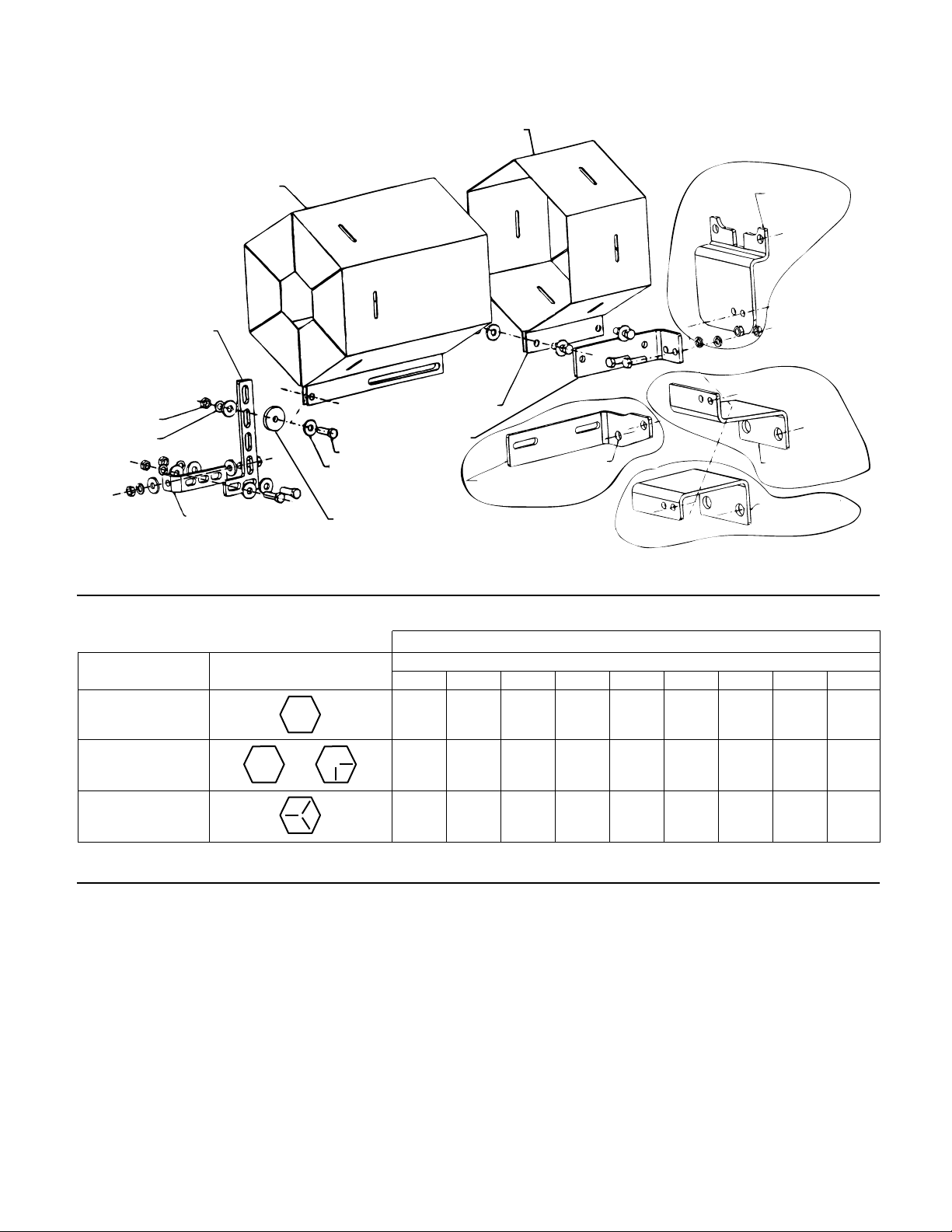
PUMP
BRACKET STYLE #2
ATTACH TO VSC/VSCS
COVERPLATE
ATTACH TO
VSC/VSCS
COVERPLATE
PUMP BRACKET STYLE #3
ATTACH TO
VSC/VSCS COVERPLATE
PUMP BRACKET STYLE #4
INNER GUARD
OUTER GUARD
SUPPORT ARM.
POSITION THE ARM BETWEEN
THE HOLES IN THE OUTER
GUARD AND HOLES IN THE
SADDLE BRACKET.
GUARD SUPPORT BRACKET
CAPSCREW
FLAT WASHER
THE GUARD SUPPORT
BRACKET ATTACHES INSIDE
HERE INLINE WITH CAPSCREWS
MOTOR SADDLE BRACKET
ATTACH TO MOTOR SADDLE
SPACER USED WITH COUPLER
GUARD KIT #2 IN PLACE OF
MOTOR SADDLE BRACKET AND
SUPPORT ARM
LOCKWASHER
NUT
PUMP BRACKET STYLE #1
BRACKET
SUPPORT ATTACH
TO BEARING
HOUSING
HEX GUARD EXPLODED VIEW FOR
TYPICAL VSC/VSCS PUMP INSTALLATION
CAPSCREW HEAD
TYPE MARKING
SAE Grade 2 6 13 25 38 60 120 190 210 300
Brass
Stainless Steel or 4 10 17 27 42 83 130 200 300
SAE Grade 5 10 20 35 60 90 180 325 525 800
DEALER SERVICING
If trouble occurs that cannot be rectified contact your local
B&G representative, He will need the following information in
order to give you assistance.
1. Complete nameplate data of pump and motor.
2. Suction and discharge pipe pressure gauge readings.
3. Ampere draw of the motor.
4. A sketch of the pump hook-up and piping.
1
/4
5
/16
CAPSCREW TORQUE (FOOT-POUND)
CAPSCREW DIAMETER
3
/8
7
/16
1
/2
5
/8
3
/4
7
/8 1
13
Page 14

Xylem
1) The tissue in plants that brings water upward from the roots;
2) a leading global water technology company.
We’re 12,000 people unified in a common purpose: creating innovative solutions
to meet our world’s water needs. Developing new technologies that will improve
the way water is used, conserved, and re-used in the future is central to our work.
We move, treat, analyze, and return water to the environment, and we help people
use water efficiently, in their homes, buildings, factories and farms. In more than
150 countries, we have strong, long-standing relationships with customers who
know us for our powerful combination of leading product brands and applications
expertise, backed by a legacy of innovation.
For more information on how Xylem can help you, go to www.xyleminc.com
Xylem Inc.
8200 N. Austin Avenue
Morton Grove, Illinois 60053
Phone: (847) 966-3700
Fax: (847) 965-8379
www.xyleminc.com/brands/bellgossett
Bell & Gossett is a trademark of Xylem Inc. or one of its subsidiaries.
© 2012 Xylem Inc. P81630E February 2012
 Loading...