

Page 1

INSTRUCTION MANUAL
P2000516
Marlow Series
Impeller Static Balancing
INSTRUCTIONS
Page 2
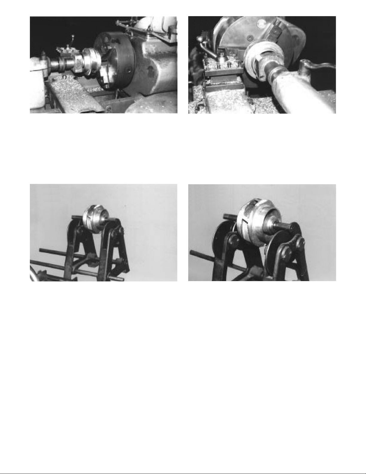
FIGURE 1
FIGURE 2
STEP 1 — When cutting the impeller O.D. it is
suggested that the tail stock of the lathe be utilized
and act as a stablizer.
FIGURE 3
STEP 2 — After impeller has been cut to size, make
certain that all burrs are removed. Insert mandril
into impeller and place on balancing ways. Spin the
impeller lightly and allow to turn until it stops rocking.
For holding the impeller in the chuck. Note the use of
a at block of wood between impeller and blunt tail
stock.
FIGURE 4
Make a chalk mark at the bottom center of the
impeller. This is the unbalanced point.
2
Page 3

FIGURE 5
STEP 3 — Place impeller in chunk on drill table. Align
at mill cutting tool at center of imbalance point on
the impeller wall. If the unbalanced condition is quite
pronounced make the rst cut about 1/64" deep and
2" to the left and right of the center point.
FIGURE 6
This is done by moving the handle attached to drill
table back and forth. A continuous balance check
should be made during this operation. The impeller is
properly balanced when it remains stationary on the
balance ways on any point of its 360º periphery.
3
Page 4

Xylem Inc.
8200 N. Austin Avenue
Morton Grove, Illinois 60053
Phone: (847) 966-3700
Fax: (847) 965-8379
www.gouldswatertechnology.com
Goulds is a registered trademark of Goulds Pumps, Inc. and is used under license.
© 2013 Xylem Inc. P2000516 March 1979
 Loading...