

Page 1
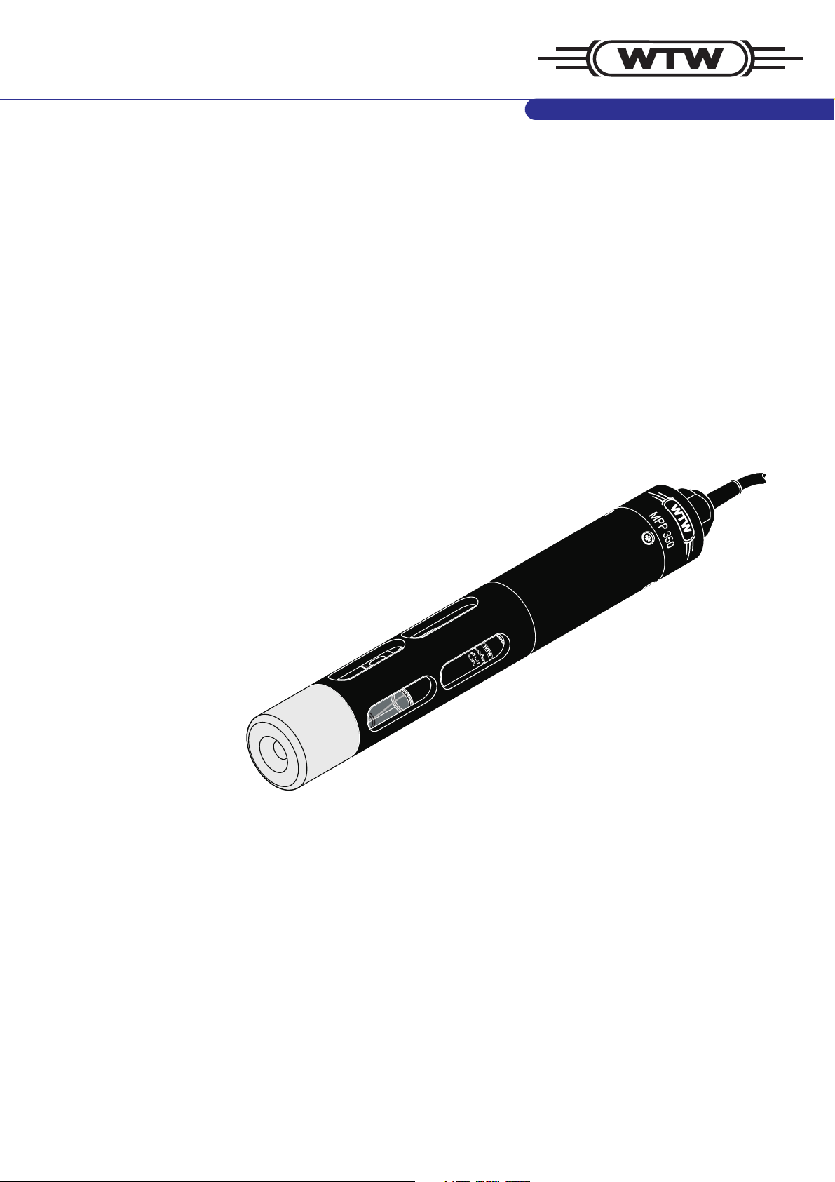
MPP 350
Operating manual
Multi parameter probe for pH, dissolved oxygen,
conductivity and temperature
ba75434e02 07/2005
Page 2

MPP 350
Accuracy when
going to press
The use of advanced technology and the high quality standard of our
instruments are the result of continuous development. This may result in
differences between this operating manual and your instrument. Also, we
cannot guarantee that there are absolutely no errors in this manual.
Therefore, we are sure you will understand that we cannot accept any legal
claims resulting from the data, figures or descriptions.
Copyright
© Weilheim 2004, WTW GmbH
Reprinting - even as excerpts - is only allowed with the explicit written
authorization of WTW GmbH, Weilheim.
Printed in Germany.
2
ba75434e02 07/2005
Page 3

MPP 350 Contents
1 Overview . . . . . . . . . . . . . . . . . . . . . . . . . . . . . . . . . . . . . . . . . . 4
1.1 Structure and function . . . . . . . . . . . . . . . . . . . . . . . . . . . . . . . . 4
1.2 Instrument identification . . . . . . . . . . . . . . . . . . . . . . . . . . . . . . 6
2 Safety . . . . . . . . . . . . . . . . . . . . . . . . . . . . . . . . . . . . . . . . . . . . . 7
3 Commissioning . . . . . . . . . . . . . . . . . . . . . . . . . . . . . . . . . . . . 7
3.1 Scopes of delivery . . . . . . . . . . . . . . . . . . . . . . . . . . . . . . . . . . . 7
3.2 Getting the sensor ready for measuring . . . . . . . . . . . . . . . . . . 9
4 Measuring / Operation . . . . . . . . . . . . . . . . . . . . . . . . . . . . . . 12
4.1 Calibration . . . . . . . . . . . . . . . . . . . . . . . . . . . . . . . . . . . . . . . . 12
4.2 Measuring . . . . . . . . . . . . . . . . . . . . . . . . . . . . . . . . . . . . . . . . 13
4.3 Storing . . . . . . . . . . . . . . . . . . . . . . . . . . . . . . . . . . . . . . . . . . . 13
5 Maintenance, cleaning, replacement . . . . . . . . . . . . . . . . . . 14
5.1 General maintenance instructions . . . . . . . . . . . . . . . . . . . . . . 14
5.2 Outside cleaning . . . . . . . . . . . . . . . . . . . . . . . . . . . . . . . . . . . 15
5.3 D.O. module: Changing the electrolyte solution and membrane
cap . . . . . . . . . . . . . . . . . . . . . . . . . . . . . . . . . . . . . . . . . . . . . . 16
5.4 D.O. module: Cleaning the electrodes . . . . . . . . . . . . . . . . . . 18
5.5 Checking the D.O. module for freedom from zero-current . . . 20
5.6 Aging of the probe . . . . . . . . . . . . . . . . . . . . . . . . . . . . . . . . . . 20
5.7 Disposal . . . . . . . . . . . . . . . . . . . . . . . . . . . . . . . . . . . . . . . . . . 21
6 What to do if... . . . . . . . . . . . . . . . . . . . . . . . . . . . . . . . . . . . . . 22
6.1 Error symptoms of D.O. measurement . . . . . . . . . . . . . . . . . . 22
6.2 Error symptoms of conductivity measurement . . . . . . . . . . . . 23
6.3 Error symptoms of pH measurement . . . . . . . . . . . . . . . . . . . 23
7 Technical data . . . . . . . . . . . . . . . . . . . . . . . . . . . . . . . . . . . . 24
7.1 Basic module with conductivity measuring cell . . . . . . . . . . . . 24
7.2 Dissolved oxygen (D.O.) module . . . . . . . . . . . . . . . . . . . . . . . 26
8 Wear parts and accessories . . . . . . . . . . . . . . . . . . . . . . . . . 29
ba75434e02 07/2005
3
Page 4

Overview MPP 350
1 Overview
1.1 Structure and function
The MPP 350 multi parameter probe is a modularly constructed sensor for
pH, dissolved oxygen, conductivity and temperature. Its maximum configuration comprises the following basic components:
! Basic module with permanently built-in conductivity measuring cell ac-
cording to the quadripole measuring principle, with integrated temperature
sensor
! Removable dissolved oxygen module, according to the galvanic measur-
ing principle
! Removable, armored pH electrode with S7 plug-in connector
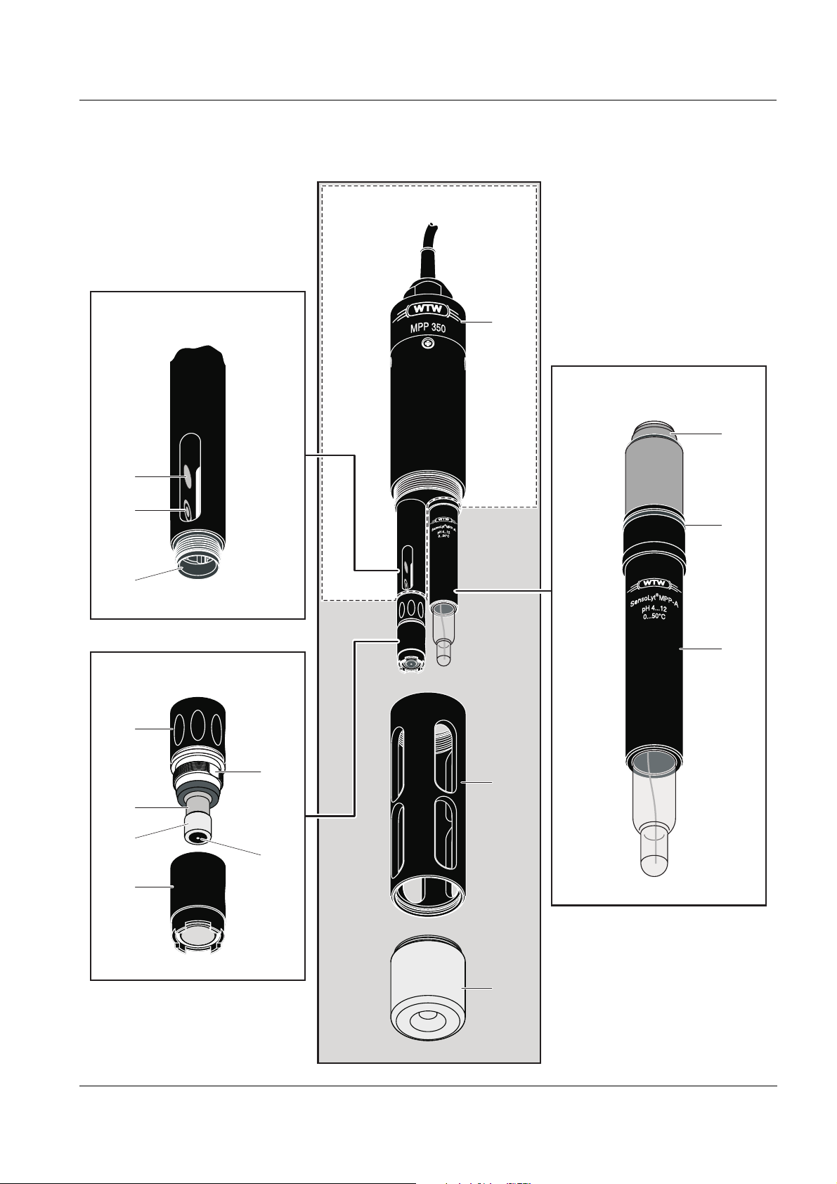
Detailed structure
(see figure on the
right page)
1 Closing head
2 Protective hood
3 Sinker
Conductivity measuring cell:
4 Temperature sensor in graphite enclosure
5 Voltage electrode (inside, 2x)
6 Current electrode (ring, 2x)
7 Plug connection for D.O. module
D.O. module:
8 Cap nut
9 Screw thread base with ventilation area
10 Lead counter electrode (anode)
11 Insulator
12 Gold working electrode (cathode)
13 Membrane cap (filled with electrolyte solution)
pH electrode:
14 S7 plug-in connector
15 Armoring
16 Sealing ring
4
ba75434e02 07/2005
Page 5
MPP 350 Overview
Basic module
Conductivity measuring cell
4
5, 6
7
D. O. module
1
pH electrode
14
16
15
8
10
11
13
ba75434e02 07/2005
9
12
2
3
5
Page 6

Overview MPP 350
The basic module is the basic component of the operable sensor. It can be
used as a stand-alone conductivity measuring cell with temperature sensor.
By mounting the D. O. module and/or pH electrode the basic module can be
extended to form a multi parameter probe for pH, dissolved oxygen, conductivity and temperature.
The D.O. module is connected to the basic module via a watertight, threepole plug connection. The conductivity measuring cell measures the temperature, which is required for the determination of the D.O. content. For this
reason the D.O. module only works in conjunction with the basic module.
The pH electrode is electrically connected to the basic module via an S7 plugin connection. It is mechanically fixed with the aid of the protective hood.
Recommended
fields of
application
! On site measurements in rivers, lakes, sea water and brackish water as
well as waste water
! Measurements in boreholes (up to a diameter of two inches) up to 100 m
depth
! Fishfarming
! Measurements in ground water and spring water
! Applications in water laboratories
1.2 Instrument identification
A series number is printed on every module. Keep these numbers ready if
you have questions to ask the WTW service department.
The series numbers contain the following information:
Basic module The number is imprinted on the shaft of the conductivity measuring cell.
12 3
04360013
1 Manufacturing year 20... (example: 2004)
2 Calendar week of manufacturing (CW 36)
3 Sequential batch number (0013)
Dissolved oxygen
(D.O.) module
pH electrode For notes concerning the series number of the electrode refer to the electrode
6
The number is imprinted on the cap nut.
1234
0442A007
operating manual.
1 Manufacturing year 20... (example: 2004)
2 Calendar week of manufacturing (CW 42)
3 Sensor type (type A)
4 Sequential batch number (007)
ba75434e02 07/2005
Page 7

MPP 350 Safety
2Safety
This operating manual contains special instructions that must be followed
during the operation of the sensor. Always keep this operating manual in the
vicinity of the sensor.
Special user
qualifications
General safety
instructions
The membrane cap of the D. O. module is filled with a small amount of an
alkaline electrolyte solution. All maintenance work that requires dealing with
the electrolyte solution must only be carried out by persons who know how to
deal with chemicals safely.
The individual chapters of this operating manual use safety labels like the one
below to indicate danger:
Caution
indicates instructions that must be followed precisely in order to avoid
slight injuries or damage to the instrument or the environment.
3 Commissioning
3.1 Scopes of delivery
3.1.1 Scope of delivery, MPP 350-x
®
! Basic module, with mounted D. O. module in the OxiCal
tion and storing vessel. The D.O. module is filled with electrolyte solution
and operable. The receptacle for the pH electrode is closed with a plug.
-MPP air calibra-
! MPP-Prot protective hood, mounted, with MPP-S sinker
! BR MPP 350 battery-powered stirrer (with cable lengths from 10 m only)
! Cable drum (with cable lengths from 40 m only)
! MPP-Cal calibration vessel for pH and conductivity
! ZBK 325 accessory set for D. O. module, comprising:
– 3 exchange membrane caps, WP 90
– Electrolyte solution, ELY/G
– Cleaning solution, RL/G
– Polishing strip, SF 300
! 1 closing cap for conductivity measuring cell
! 1 closing cap for D.O. module
! 1 plug for electrode receptacle
! Operating manual for MPP 350
! CD-ROM Update Multi 350i
ba75434e02 07/2005
7
Page 8
Commissioning MPP 350
Note
The membrane cap that is mounted on the D.O. sensor for delivery serves
mainly as a transport protection. Depending on the duration of the transport
and storage period, it may have a shortened operational lifetime. If the measuring system cannot be calibrated (error message on the instrument),
please proceed according to section 5.3 D.O.
TROLYTE SOLUTION AND MEMBRANE CAP.
MODULE: CHANGING THE ELEC-
3.1.2 Set equipment
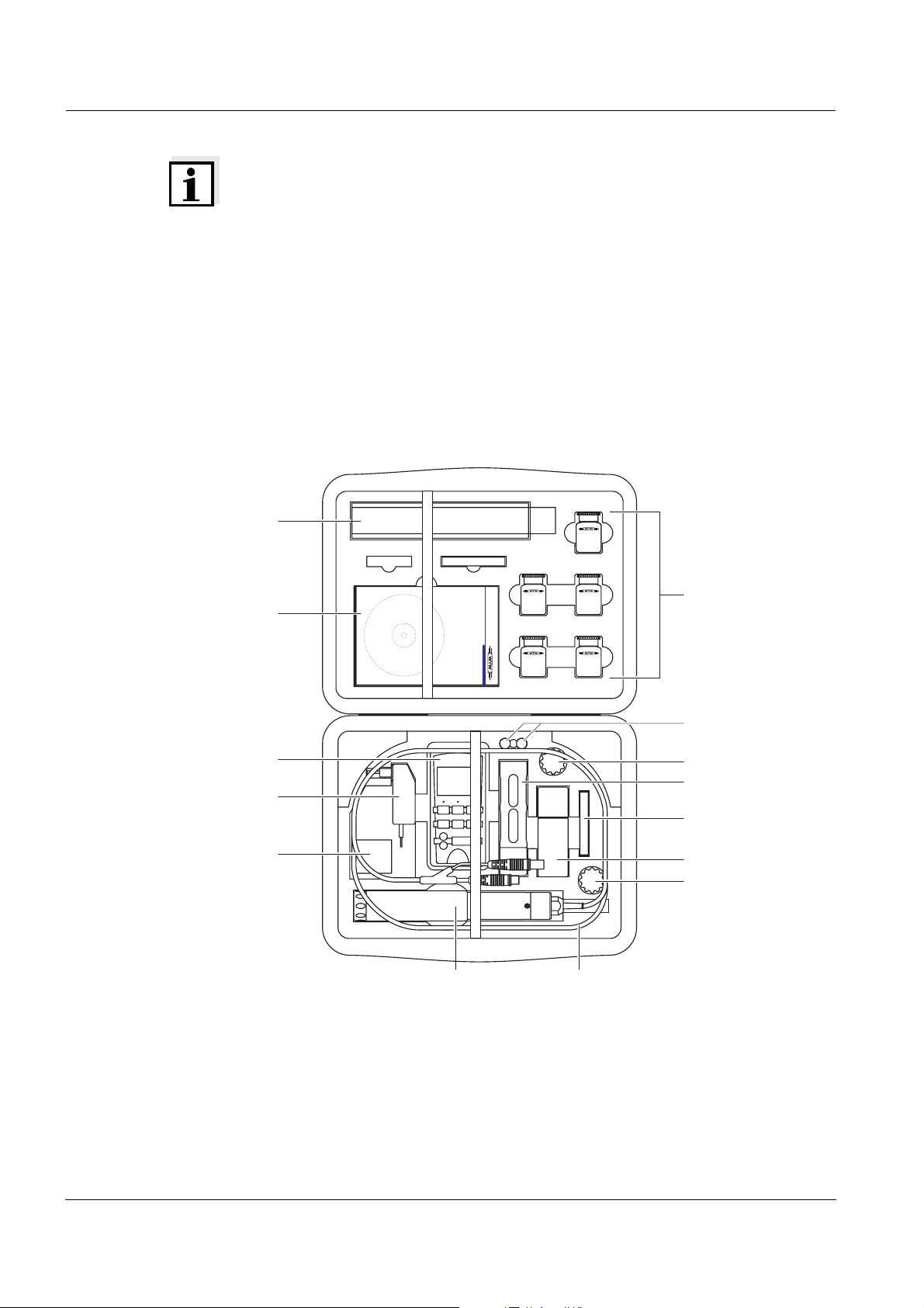
The MPP 350 is also available as a set in the MPP-FC field case. You can
also buy the carrying case as an accessory and fit it with components yourself. Electrodes with a cable length of up to 25 m fit in the carrying case. Ordering information, see chapter 8 W
EAR PARTS AND ACCESSORIES.
Equipment of the
field case
MPP-FC
1
(example)
2
3
4
5
67
1 Electrode or battery-powered
8 Reagents (buffers etc...)
stirrer
2 Manual, CD-ROM 9 Plug
8
9
8
10
11, 12
13
8
3 Meter 10 Protective hood with sinker
4 Plug-in power supply unit 11 Exchange membrane caps
8
ba75434e02 07/2005
Page 9
MPP 350 Commissioning
4
5 Small parts (adapters etc...) 12 Polishing film
®
6 MPP 350 with OxiCal
-MPP 13 pH/cond calibration vessel
7 Connection cable
3.2 Getting the sensor ready for measuring
3.2.1 Measurements without D. O. module
Make sure that the plug connector of the conductivity measuring cell is tightly
closed with the suitable closing cap. When mounted, the closing cap (1) must
be screwed on up to the stop.
2
Before screwing on the closing cap, check the following points:
! The sealing (2) must be clean and evenly positioned in the groove.
1
! The plug connection and the inside of the closing cap must be clean and
dry.
3.2.2 Measurements without pH electrode
Make sure the electrode receptacle on the basic module (1) is tightly closed
with the plug (2) and the protective hood (4) is screwed on up to the stop. Be-
1
fore plugging in, check whether the sealing (3) of the plug is clean and correctly positioned. The sealing should always be slightly greased (with the O
ring grease of the pH electrode).
3
2
Caution
Never operate the MPP 350 without the protective
hood. The protective hood fixes the pH electrode or
plug in the electrode receptacle and guarantees a pressure-resistant sealing. It especially protects the pH
electrode from mechanical damage.
ba75434e02 07/2005
9
Page 10

Commissioning MPP 350
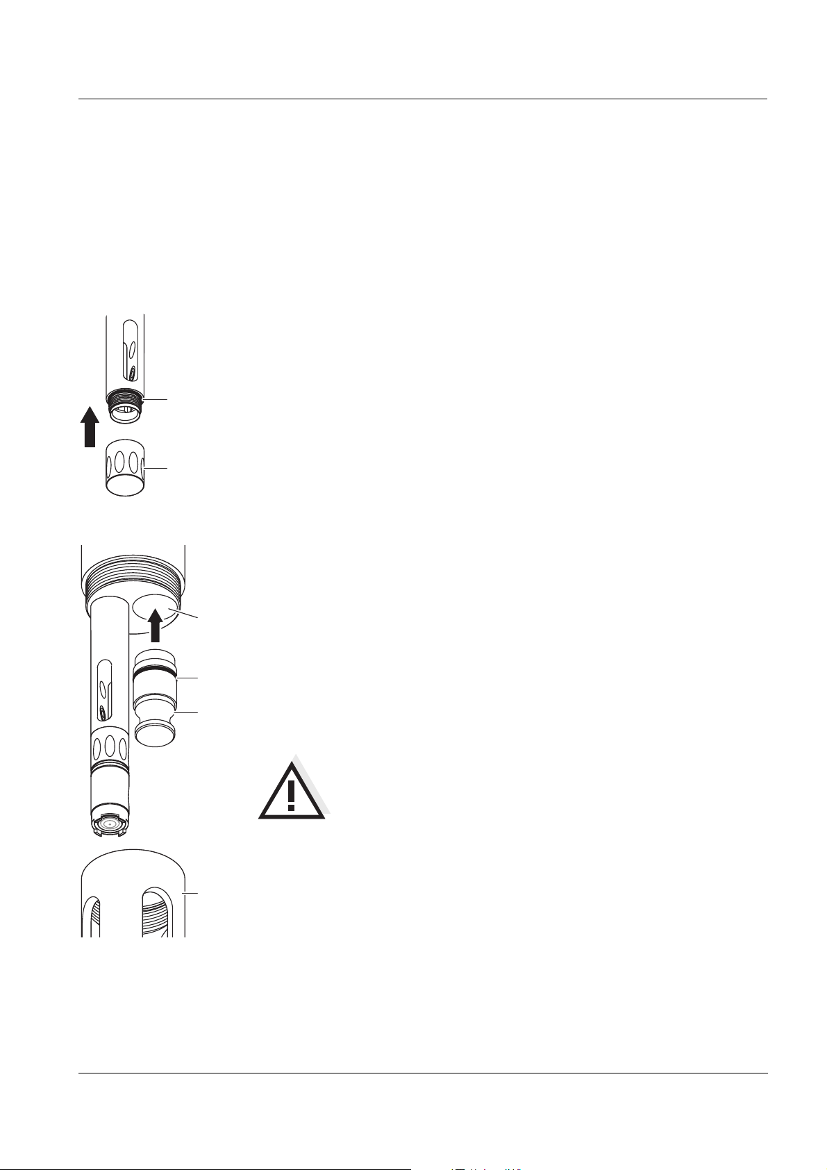
3.2.3 Mounting the D. O. module
Make sure that the D.O. module and conductivity measuring cell are screwed
together tightly. When mounted, the cap nut of the D.O. module has to be
screwed on up to the stop.
3
Before screwing on the D.O. module, check the following points:
! The sealing (3) must be clean and evenly positioned in the groove.
2
1
Screwing on the
D.O. module
Unscrewing and
storing the D. O.
module
4
! The plug connection must be clean and dry on both sides.
Position the D.O. module (1) on the conductivity measuring cell and carefully
and with slight pressure turn it until the guiding nib on the D.O. module locks
in place in the corresponding groove on the conductivity measuring cell.
Subsequently tighten the cap nut (2) up to the stop. The thread only snatches
if the D.O. module was correctly positioned.
Unscrew the cap nut and remove the D.O. module from the conductivity basic
module.
Caution
Inappropriate handling can lead to the release of electrolyte solution. When unscrewing the D.O. module
only turn the cap nut (not the membrane cap!).
For storing, mount the clean and dry closing cap (4) on the D. O. module.
Thus the plug connection will remain optimally protected.
10
ba75434e02 07/2005
Page 11

MPP 350 Commissioning
4
3.2.4 Mounting the pH electrode
Mount the electrode:
! If necessary, remove the plug from the electrode receptacle (1).
1
! Protect the pH electrode with the watering cap (4).
! Push the electrode (2) into the electrode receptacle up to the stop. When
doing so make sure the sealing (3) is clean and greased and correctly positioned in the groove.
3
! Remove the watering cap (4).
! Screw on the protective hood.
2
Caution
Never operate the MPP 350 without the protective
hood. The protective hood fixes the pH electrode or
plug in the electrode receptacle and guarantees a pressure-resistant sealing. It especially protects the pH
electrode from mechanical damage.
Note
For further notes concerning the series number of the elec-
5
trode refer to the electrode operating manual.
ba75434e02 07/2005
3.2.5 Preparing the measuring operation
Connect the sensor to the measuring instrument. The sensor is immediately
ready to measure. It is not necessary to polarize the D.O. module.
Note
For acclimatization before and after measuring and to protect the sensor from
external influences during periods of non-use we recommend to mount the
OxiCal
®
-MPP calibration and storing vessel equipped with a moist sponge on
the sensor.
11
Page 12

Measuring / Operation MPP 350
4 Measuring / Operation
4.1 Calibration
4.1.1 Calibrating for D. O. measurement
To calibrate the D.O. module, use the OxiCal
®
-MPP calibration and storage
vessel (white). It is screwed on the sensor instead of the protective hood.
Make sure that the sponge in the calibration vessel is always moist.
Moisten the sponge:
! Unscrew the lid (1).
! Take out the sponge (2) out of the lid, wet it, then slightly squeeze it out.
! Reinsert the sponge and close the calibration vessel with the cap.
2
1
Note
Please read the further course of the calibration in the operating manual of
the meter.
4.1.2 Calibrating for conductivity and pH measurement
To calibrate the conductivity measuring cell or pH electrode, use the MPPCAL calibration vessel (transparent). Fill the calibration vessel with enough
buffer solution or conductivity control standard so that the solution at least
reaches the marking groove (1) when the calibration vessel is screwed on.
Thus the temperature sensor is always immersed in the solution and
calibration can be carried out correctly.
12
1
Note
Depending on the number of modules mounted, different filling quantities are
required for the solution to reach up to the marking groove (1) (minimum
filling level) so that the temperature sensor is immersed in the measuring
solution.
Note
Please read the further course of the calibration in the operating manual of
the meter.
ba75434e02 07/2005
Page 13

MPP 350 Measuring / Operation
4.2 Measuring
Please always observe the required minimum immersion depth and the
minimum approach flow that is important for D.O. measurements (see
chapter 7 T
ECHNICAL DATA).
The minimum flow can be provided in different ways, e. g.:
! The flow of the water to be measured is sufficient (aeration tank, water
pipe, stream)
! Slowly pull the sensor through the water by hand (lake, container), or
! Use a flow aid, e. g. a magnetic stirrer or the battery-powered stirrer,
BR MPP 350. The battery-powered stirrer BR MPP 350 also serves as a
protective hood at the same time and is screwed on instead of the standard protective hood.
Caution
If the BR 325 MPP is used in salt water (seawater, brackish water), thoroughly rinse and clean with tapwater
A
u
E
s
in
O
f
f
O
n
(freshwater!) afterwards. Otherwise, corrosion damage
may occur.
Battery-powered
stirrer,
BR MPP 350
4.3 Storing
The sensor with the D.O. module must always be stored in the calibration
vessel. Make sure that the sponge in the calibration vessel is always moist.
Note
For further notes concerning the storing of the electrode refer to the electrode
operating manual.
ba75434e02 07/2005
13
Page 14

Maintenance, cleaning, replacement MPP 350
5 Maintenance, cleaning, replacement
5.1 General maintenance instructions
For your safety Note the following safety instructions when handling electrolyte and cleaning
solutions:
Caution
The ELY/G electrolyte solution and the RL/G cleaning solution irritate
the eyes and skin. Observe the following points when handling the solutions:
! During working activities, always wear suitable protective gloves
and protective goggles/face shield.
! If it comes into contact with the skin, rinse thoroughly with water and
immediately change contaminated clothing.
! If it comes into contact with the eyes, rinse thoroughly with water
and consult a doctor.
! Follow the safety datasheet.
Maintenance
activities on the
D.O. module
Caution
Before all maintenance activities, disconnect the sensor from the instrument.
Note
Information on how to order wear parts and maintenance equipment can be
found in chapter 8 W
For better handling, leave the D.O. module screwed on the conductivity
measuring cell. Thus, you can better immerse the sensor head in the
electrolyte or cleaning solution and the plug connection remains protected
against damage.
EAR PARTS AND ACCESSORIES.
14
ba75434e02 07/2005
Page 15

MPP 350 Maintenance, cleaning, replacement
5.2 Outside cleaning
Basic module and
Contamination Cleaning procedure
D.O. module
Lime sediments Immerse in acetic acid (volume share =
20 %) for 1 minute
Fat/oil Clean with warm water that contains wash-
ing-up liquid
After cleaning, thoroughly rinse with deionized water and recalibrate if
necessary.
pH electrode For further notes concerning the cleaning of the electrode refer to the elec-
trode operating manual.
ba75434e02 07/2005
15
Page 16

Maintenance, cleaning, replacement MPP 350
5.3 D.O. module: Changing the electrolyte solution and mem-
brane cap
Caution
Before starting to work with the sensor, please note the GENERAL MAIN-
TENANCE INSTRUCTIONS on page 14.
General
information
WTW delivers the D.O. module ready to use (see section 3). The electrolyte
solution and membrane cap must only be replaced if:
! a calibration error occurs and the membrane is heavily contaminated
! the membrane is damaged
! the electrolyte solution is exhausted.
Changing the electrolyte solution and membrane cap
Unscrew the membrane cap.
Caution:
Electrolyte solution!
Rinse the sensor head with
deionized water.
For disposal of the membrane
cap and electrolyte solution,
see section 5.7.
Carefully rub and dry the
counter electrode with a lintfree paper towel.
RL-G H O
Immerse the sensor head including the counter electrode
in RL/G cleaning solution.
Allow to react for 1 to 3 minutes.
16
Thoroughly rinse the sensor
head with deionized water.
2
Water the counter electrode in
deionized water for at least
10 minutes.
ba75434e02 07/2005
Page 17

MPP 350 Maintenance, cleaning, replacement
ELY/G
Carefully shake off the drops
of water.
ELY/G
Thoroughly rinse the sensor
head with electrolyte solution.
Fill a new membrane cap with
ELY/G electrolyte solution.
Ventilation area
points upwards
Hold the sensor inclined and
screw on the membrane cap
fingertight using a paper towel. Excess electrolyte solution
is forced out of the ventilation
area.
Remove any air bubbles by
carefully tapping the membrane cap. Additionally, you
can prevent air bubbles by
throwing the first filling away
and refilling the membrane
cap.
4mm
Check the filling:
Inspect the face surface. No
air bubbles may be present
within the dashed circle. Air
bubbles outside this area do
not interfere.
Note
For measurements under high pressure the filling must be completely free of air bubbles.
Readiness to measure The D.O. module is ready for operation after approx. 30 to 50 min-
utes. Subsequently calibrate the sensor for D.O. measurements.
Note
If you want to measure very low D.O. concentrations (< 0.5 % saturation), we recommend to let the sensor rest overnight and then
calibrate it.
ba75434e02 07/2005
17
Page 18

Maintenance, cleaning, replacement MPP 350
5.4 D.O. module: Cleaning the electrodes
Caution
Before starting to work with the sensor, please note the GENERAL MAIN-
TENANCE INSTRUCTIONS on page 14.
General
information
Cleaning is only required in cases of slopes too small or too large (sensor
cannot be calibrated) that cannot be resolved by changing the membrane cap
and electrolyte solution.
Cleaning the electrodes
Unscrew the membrane cap.
Caution:
Electrolyte solution!
For disposal of the membrane
cap and electrolyte solution,
see section 5.7.
Rinse the sensor head with
deionized water.
SF 300
Using the rough side of the
wet SF 300 polishing strip,
polish off any contamination
from the gold working electrode using light pressure.
Caution:
ventional sandpaper or glassfiber brushes.
Do not use any con-
Rinse the sensor head with
deionized water.
18
Wipe the counter electrode
with a lint-free paper towel
and carefully remove any
loose white deposits.
RL-G
Immerse the sensor head including the counter electrode
in RL/G cleaning solution.
Allow to react for 1 to 3 minutes.
ba75434e02 07/2005
Page 19

MPP 350 Maintenance, cleaning, replacement
H O
2
Thoroughly rinse the sensor
head with deionized water.
ELY/G
Fill a new membrane cap with
ELY/G electrolyte solution.
Water the counter electrode in
deionized water for at least
10 minutes.
Remove any air bubbles by
carefully tapping the membrane cap. Additionally, you
can prevent air bubbles by
throwing the first filling away
and refilling the membrane
cap.
Carefully shake off the drops
of water.
ELY/G
Rinse the sensor head with
electrolyte solution.
Ventilation area
points upwards
Hold the sensor inclined and
screw on the membrane cap
fingertight using a paper towel. Excess electrolyte solution
is forced out of the ventilation
area.
ba75434e02 07/2005
4mm
Check the filling:
Inspect the face surface. No
air bubbles may be present
within the dashed circle. Air
bubbles outside this area do
not interfere.
19
Page 20

Maintenance, cleaning, replacement MPP 350
Note
For measurements under high pressure the filling must be completely free of
air bubbles.
Readiness to mea-
sure
After approx. 30 to 50 minutes, the sensor is ready for operation. Subsequently calibrate the sensor.
Note
If you want to measure very low D.O. concentrations (< 0.5 % saturation), we
recommend to let the sensor rest overnight and then calibrate it.
5.5 Checking the D.O. module for freedom from zero-current
The D.O. module is free from zero-current. Checking the module for freedom
from zero-current is only necessary in the case of malfunctions that cannot
be remedied by exchanging the electrolyte solution and membrane cap or by
cleaning the electrodes.
There are two possibilities to check the D.O. module for freedom from zerocurrent:
! Measurement in a nitrogen atmosphere (recommended method)
! Measurement in a sodium sulfite solution according to DIN EN 25814/
ISO 5814.
Caution
If you check the sensor according to DIN EN 25814/ISO 5814, do not
leave the sensor in the sodium sulfite solution for more than 2 minutes.
Danger of sensor poisoning!
Test criterion The D.O. module is OK if the measuring instrument displays < 1 % D.O.
saturation after 2 minutes.
5.6 Aging of the probe
Except for the pH electrode, the probe does not naturally age when used
according to instructions. Special measuring media (e.g. strong acids and
lyes, organic solvents) or too high temperatures shorten the operational
lifetime considerably or damage the probe. The warranty does not cover
cases where such conditions cause failure or mechanical damage.
20
ba75434e02 07/2005
Page 21

MPP 350 Maintenance, cleaning, replacement
5.7 Disposal
Caution
The ELY/G electrolyte solution irritates eyes and skin. When dealing
with the ELY/G electrolyte solution, observe the following points:
! During working activities, always wear suitable protective gloves
and protective goggles/face shield.
! If it comes into contact with the skin, rinse thoroughly with water and
immediately change contaminated clothing.
! If it comes into contact with the eyes, rinse thoroughly with water
and consult a doctor.
! Follow the safety datasheet.
Basic module, D.O.
module and
membrane cap
Electrolyte
solution and
cleaning solution
pH electrode Disposal see operating manual of the electrode.
For disposal, unscrew the membrane cap from the D.O. module. Then rinse
the entire sensor and the membrane cap with water.
We recommend to dispose of the basic module and D.O. module without
membrane cap as electronic waste. The membrane cap may be disposed of
with the household refuse.
Disposal according to the safety data sheet.
ba75434e02 07/2005
21
Page 22

What to do if... MPP 350
6 What to do if...
6.1 Error symptoms of D.O. measurement
Error symptom Cause Remedy
No D.O. display – No connection between meter and
sensor
– D.O. module not mounted
properly
– Cable defective
The sensor is in the air
and the display shows
0.0 mg/l or 0 % O
2
– No connection between meter and
sensor
– D.O. module not mounted
properly
– No electrolyte in the membrane
cap
– Cable defective
The sensor cannot be
calibrated
– Contaminated membrane cap
– Electrolyte depleted
– Membrane damaged
The sensor still cannot
be calibrated after
changing the electrolyte
and membrane cap
Incorrect temperature
display
– Contaminated electrodes or
sensor toxification
– Membrane cap not screwed on
tight enough
– The temperature sensor of the
conductivity measuring cell is not
immersed in the measuring
solution
– Temperature sensor defective
– Check connection between meter
and sensor
– Check the plug-in connection,
clean the contacts as necessary
– Return the sensor
– Check connection between meter
and sensor
– Check the plug-in connection,
clean the contacts as necessary
– Replace and refill the membrane
cap (see section 5.3)
– Return the sensor
– Replace and refill the membrane
cap (see section 5.3)
Subsequently, wait for 30 to
50 min and recalibrate.
– Clean the electrodes (see
section 5.4)
– Screw membrane cap tighter
– Observe the minimum immersion
depth
– Return the sensor
Measured values implausible
Mechanical damage to
the sensor
22
– Incident flow insufficient – Move the sensor in the test
sample (stirr) or use the batterypowered stirrer, BR MPP 350
– Return the sensor
ba75434e02 07/2005
Page 23

MPP 350 What to do if...
6.2 Error symptoms of conductivity measurement
Error symptom Cause Remedy
No temperature or conductivity display
Measurement delivers
implausible conductivity
values
– No connection between meter and
sensor
– Cable defective
– Incorrect cell constant adjusted at
the meter
– Measuring range exceeded
– Contamination in the area of the
electrodes
– Check connection between meter
and sensor
– Return the sensor
– Check / correct the cell constant
– Observe the application range
– Clean the sensor (see
section 5.2).
– Return the sensor
– Electrodes damaged
Incorrect temperature
display
– The temperature sensor was not
immersed in the measuring
– Observe the minimum immersion
depth
solution
– Temperature sensor defective
– Return the sensor
6.3 Error symptoms of pH measurement
Error symptom Cause Remedy
No pH display – No connection between meter and
sensor
– Cable defective
– pH electrode defective
– Check connection between meter
and sensor
– Return the sensor
– Replace pH electrode
ba75434e02 07/2005
23
Page 24

Technical data MPP 350
7 Technical data
7.1 Basic module with conductivity measuring cell
General features Measuring principle Four-electrode measurement
Cell constant 0.475 cm
Temperature sensor integrated NTC 30 (30 kΩ/ 25 °C)
-1
±1.5 %
Dimensions
287.5
(in mm)
Weight Probe approx. 135 g
(without cable, sinker, pH electrode and D.O.
module)
Sinker approx. 500 g
Materials Enclosure of the basic mod-
POM
ule
Connection head of the
POM
basic module
Shaft of the conductivity
Epoxy
measuring cell
Plug connection for
PEEK
D.O. module
Conductivity electrodes Graphite
247
41.5
24
Thermistor enclosure Graphite
Sealings (O rings) FPM (Viton
Closing cap for conductivity
PVC
measuring cell
pH plug POM
®
)
ba75434e02 07/2005
Page 25

MPP 350 Technical data
Connection cable Lengths 3 / 6 / 10 / 15 / 25 m
Diameter 6,1 mm
Smallest allowed
bend radius
Permanent bend: 60 mm
Single time or short time bend>: 35 mm
Material Kabelmantel PVC, stabilisiert
Lengths 40 / 60 / 100 m
Diameter 8,0 mm
Smallest allowed
bend radius
Permanent bend: 67,5 mm
Single time or short time bend>: 40 mm
Cable sheath material PUR
Steckertyp Cond/Oxi: Buchse, 8-polig
pH: DIN-Stecker
Connector for D.O.
module
Electrode
receptacle
Pressure
resistance
Measurement
conditions
3-pole, watertight plug connection with cap nut, reverse polarity protected,
contacts gold-plated
S7 plug-in connector. The electrode is fixed by the protective hood
Sensor with closed plug
IP 68 (10
6
Pa or 10 bar)
connection
Cable plug IP 67 (when plugged in)
The MPP 350 meets the requirements according to article 3(3) of the
97/23/EC directive ("Pressure equipment directive").
Conductivity measuring
1 µS/cm ... 2 S/cm
range
Temperature range 0 ... 50 °C
Max. allowed overpressure 10
6
Pa (10 bar)
Depth of immersion min. 130 mm (with protective hood and sink-
er)
max. 100 m (depending on the cable length)
Operating position any
Storage
conditions
Characteristic data
on delivery
ba75434e02 07/2005
Recommended storing
method
in the OxiCal
or dry (without D.O. module and electrode)
Storage temperature 0 ... 50 °C
Temperature responding
behavior
Precision of the temperature
t
(99 % of the final value display after)
99
<20s
±0.3K
sensor
®
-MPP calibration vessel (moist)
25
Page 26

Technical data MPP 350
7.2 Dissolved oxygen (D.O.) module
General features Measuring principle Membrane covered galvanic sensor
Temperature compensation IMT compensation (calculated by the meter)
Dimensions
(in mm)
Weight approx. 20 g (filled with electrolyte)
Materials Working electrode Gold
Counter electrode Lead
– Membrane cap
POM
– Cap nut
Membrane FEP, 13 µm
– Sensor head Epoxy, PEEK
– Plug connection PEEK
Screw thread base Stainless steel 1.4571
Seals FPM (Viton)
Closing cap POM
Plug connection Plug type 3-pole, watertight plug connection with cap
nut, reverse polarity protected, contacts
gold-plated
Pressure
resistance
Sensor with closed plug
connection
IP 68 (10
6
Pa or 10 bar)
The D.O. module meets the requirements according to article 3(3) of the 97/
23/EC directive ("Pressure equipment directive").
26
ba75434e02 07/2005
Page 27

MPP 350 Technical data
Measurement
conditions
Storage
conditions
Measuring ranges at 20 °C 0 ... 50 mg/l D.O.
0 ... 600 % D.O. saturation
0 ... 1250 mbar D.O. partial pressure
Polarization time min. 30 ... 50 min after changing the electro-
lyte,
it is not necessary to connect the sensor to
the meter for polarization
Temperature range 0 ... 50 °C
Max. allowed overpressure 10
Depth of immersion with
conductivity basic module
6
Pa (10 bar)
min. 130 mm (with protective hood and sinker)
max. 100 m (depending on the cable length)
Operating position any
Approach flow > 3 cm/s at 10 % measurement accuracy
10 cm/s at 5 % measurement accuracy
18 cm/s at 1 % measurement accuracy
Recommended storing
method
in the OxiCal
ened)
®
-CX calibration vessel (moist-
Storage temperature 0 ... 50 °C
Characteristic data
on delivery
Zero signal < 0.1 % of the saturation value
Response time at 20 °Ct
(90 % of the final value display after)
90
<10s
t
(95 % of the final value display after)
95
<16s
t
(99 % of the final value display after)
99
<60s
Own consumption of oxy-
0.008 µg·h
-1
(mg/l)
-1
gen at 20 °C
Drift approx. 3 % per month in the operating con-
dition
Working life min. 6 months with one electrolyte filling
ba75434e02 07/2005
27
Page 28

Technical data MPP 350
Pin assignment
28
ba75434e02 07/2005
Page 29

MPP 350 Wear parts and accessories
8 Wear parts and accessories
Wear parts and
maintenance
equipment
Description Model Order no.
Set of exchange membrane caps (3 pieces) WP 90/3 202 725
Electrolyte solution ELY/G 205 217
Cleaning solution for lead counter electrode RL/G 205 204
Polishing film SF 300 203 680
Accessory set, comprising:
ZBK 325 202 706
– 3 exchange membrane caps, WP 90
– Electrolyte solution, ELY/G
– Cleaning solution, RL/G
– Polishing strip, SF 300
Spare parts set, comprising:
ACC-MPP 401 145
– 1 closing cap for conductivity measuring
cell
– 1 closing cap for D.O. module
– 1 pH plug for basic module
– Sealing for plug connection
– O ring grease
– OxiCal
Spare D.O. module ConOx
®
-MPP sponge
401 070
Ox-Modul
Spare protective hood MPP-Prot 401 160
Spare sinker MPP-S 401 159
Accessories Description Model Order no.
pH electrode SensoLyt
®
401 152
MPP-A
Protective lid for standard protective hood MPP-SK 401 162
Field case MPP-FC 401 157
Calibration and storage vessel OxiCal
®
-MPP 205 405
pH/conductivity calibration vessel MPP-Cal 401 155
pH buffers (1 liter) TEP 4
TEP 7
TEP 10 Trace
Calibration and control standard
E-SET 300 572
108 700
108 702
108 703
KCl 0.01 mol/l (6 x 50 ml)
Note
For further accessories, refer to the WTW catalog or the Internet.
ba75434e02 07/2005
29
Page 30

Wear parts and accessories MPP 350
30
ba75434e02 07/2005
 Loading...