

Page 1

Series 63
Low Water Cut-Off
Typical Applications:
- Primary or secondary low water cut-off
for hot water and steam boilers.
- Low water cut-off
- High water cut-off
- Alarm actuator
OPERATION
Maximum Boiler Pressure: 50 psi (3.5 kg/cm2)
Electrical Ratings
Motor Switch Rating (Amperes)
Voltage
120 VAC 10.2
240 VAC 5.1 30.6
Full Load Locked Rotor
61.2 125 VA at
Pilot Duty
120 or 240 VAC
INSTRUCTION MANUAL
MM-206F
CUT OFF
LEVEL
Model 63
WARNING
!
CAUTION
WARNING
• Before using this product read and understand instructions.
• Save these instructions for future reference.
• All work must be performed by qualified personnel trained in the proper application, installation, and maintenance of plumbing, steam, and electrical equipment and/or systems in
accordance with all applicable codes and ordinances.
• To prevent serious burns, the boiler must be cooled to 80˚F (27˚C) and the pressure must be
0 psi (0 bar) before servicing.
To prevent electrical shock, turn off the electrical power before making electrical connections.
•
• This low water cut-off must be installed in series with all other limit and operating controls
installed on the boiler. After installation, check for proper operation of all of the limit and
operating controls, before leaving the site.
• We recommend that secondary (redundant) Low Water Cut-Off controls be installed on all
steam boilers with heat input greater than 400,000 BTU/hour or operating above 15 psi of
steam pressure. At least two controls should be connected in series with the burner control
circuit to provide safety redundancy protection should the boiler experience a low water
condition. Moreover, at each annual outage, the low water cut-offs should be dismantled,
inspected, cleaned, and checked for proper calibration and performance.
• To prevent serious personal injury from steam blow down, connect a drain pipe to the control
opening to avoid exposure to steam discharge.
• To prevent a fire, do not use this low water cut-off to switch currents over 10.2A, 1/2 Hp at
120 VAC or 5.1A, 1/2 Hp at 240 VAC, unless a starter or relay is used in conjunction with it.
California Proposition 65 warning! This product contains chemicals known to the
•
state of California to cause cancer and birth defects or other reproductive harm.
Previous controls should never be installed on a new system. Always install new
•
controls on a new boiler or system.
Failure to follow this warning could cause property damage, personal inj ury or death.
CAUTION:
•
A more frequent replacement interval may be necessary based on the condition of
the unit at time of inspection. McDonnell Miller s warranty is one (1) year from date
of installation or two (2) years from the date of manufacture.
!
&
'
Page 2
Gauge Glass Mounted
Directly into Boiler
CUT-OFF
LEVEL
1" BLOW DOWN
VALVE
For Boilers with
Independent Water Columns
1" STEAM
EQUALIZING PIPE
MODEL 63
LOW WATER
CUT-OFF
1" WATER
EQUALIZING PIPE
1" WATER
EQUALIZING PIPE
1" WATER
EQUALIZING PIPE
CUT-OFF
LEVEL
MODEL 63
LOW WATER
CUT-OFF
2
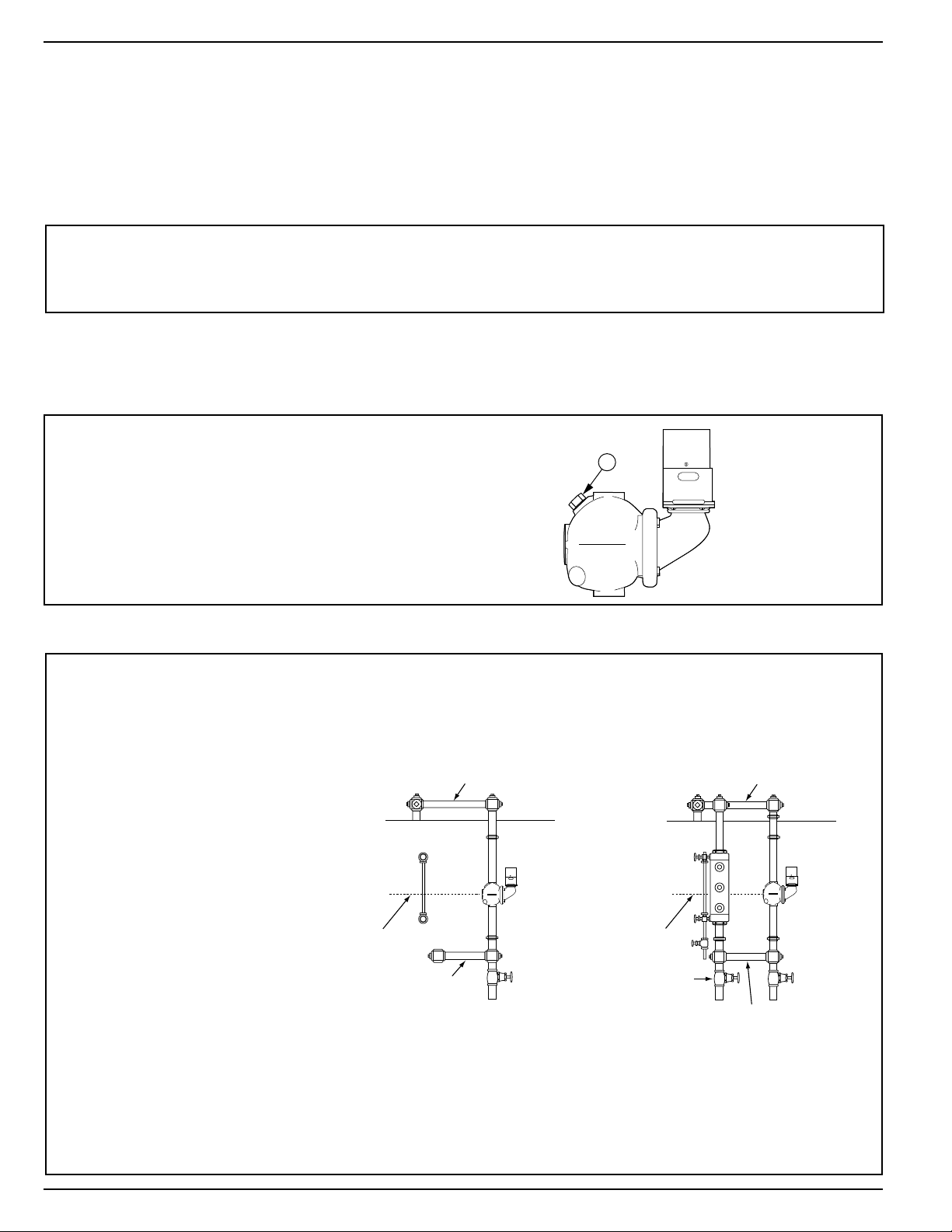
a. Whether the gauge glass is mounted directly into the boiler or on an independent water column, the
cut-off line on the 63 body casting should be mounted 1/2” (15mm) above the lowest visible point of the
gauge glass.
a. Locate the gauge glass and
determine the level that the 63
has to be mounted at in order
to achieve the criteria in Step 1.
b. Pipe the 63 following the
diagrams shown to the right.
Follow the diagram that
represents your boiler.
c. Crosses should be used at
each right angle connection for
inspection and cleaning.
d. Make sure the blow-down
valves are full port.
e. While the burner is operating,
open the blow-down valve,
causing the water level to drop in
the float chamber while burner is
operating. As the float drops the
alarm circuit (if used) closes first;
then on further drop the cut-off
circuit will open, shutting the
burner off.
f. Test the Model 63 before leaving
the site.
STEP 2 - Installation of the Model 63
Model 63 – For Steam Boilers with 1” (25mm) Equalizing Lines
INSTALLATION –
TOOLS NEEDED:
One (1) flathead screwdriver and two (2) pipe wrenches.
STEP 1 - Determine the Location of the Low Water Cut-Off
For 63 models with float block
CUT OFF
LEVEL
A
Using pipe wrench
• Remove float blocking plug (A) from low
water cut-off body tapping.
• Screw 3/4” NPT steel plug (provided) in
tapping.
Page 3
3
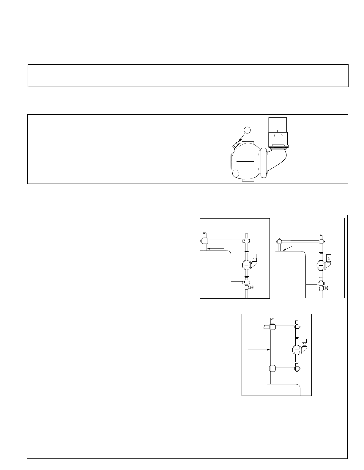
a. The line on the casting of the model 63 must be installed above the lowest permissible water level
determined by the boiler manufacturer.
a. Study the figures to the right and determine which
figure shows how the 63 control will be attached to
the boiler.
Figure 1. Connect the upper equalizing pipe to
the riser going to the radiation or to the compression
tank. Connect the lower equalizing pipe to any
available opening in the side of the boiler. NOTE: If
no opening is available in the side of the boiler,
connect the lower equalizing pipe into the drain
connection.
Figure 2. If there is a tapping available on the
top of the boiler, connect the upper equalizing pipe to
it. NOTE: During initial filling or after blow-down the
upper equalizing pipe and possibly the 63 control will
have an air pocket. Connect a vent or bleed valve on
the top of the vertical equalizing pipe. If the Test-NCheck (TC-4) valve is used the vacuum breaker can
be used to bleed the air pocket.
CAUTION: When bleeding an air pocket manually,
protect yourself from being burned with hot water.
Figure 3. If there is no tapping available on the boiler,
connect both the upper and lower equalizing pipe
into the vertical riser going to the radiation or to the
compression tank. IMPORTANT: The horizontal equalizing
pipe should be below the horizontal run going to the
radiation. If it is not, an air pocket will be created and
a vent or bleed will have to be installed.
b.
While the burner is operating open the blow-down
valve, causing the water level to drop in the float
chamber. As the float drops the alarm circuit (if used)
closes first; then on further drop the cut-off circuit will
open, shutting the burner off.
c. Test the Model 63 before leaving the site.
STEP 2 - Installation of the Model 63
Model 63 – For Hot Water Boilers with 1” (25mm) Equalizing Lines
INSTALLATION –
TOOLS NEEDED: One (1) flathead screwdriver and two (2) pipe wrenches.
For float type controls it is recommended that Test-N-Check
®
(TC-4) valves be used in the upper and
lower equalizing lines. They offer a functional means for testing the 63 control, and conform to the
ASME CSD-1 code.
STEP 1 - Determine the Location of the Low Water Cut-Off
VERTICAL RISER
TO RADIATION
HOT WATER
BOILER
MODEL
63
Figure 1
Figure 2
Figure 3
For 63 models with float block
CUT OFF
LEVEL
A
Using pipe wrench
• Remove float blocking plug (A) from low
water cut-off body tapping.
• Screw 3/4” NPT steel plug (provided) in
tapping (A).
VERTICAL RISER TO RADIATION
OR COMPRESSION TANK
TC-4
AVAILABLE OPENING
IN TOP BOILER
AIR
VENT
HOT WATER
BOILER
MODEL
63
HOT WATER
BOILER
MODEL
TC-4
63
Page 4

4
1. Assemble the TC-U (the upper Test-N-Check
valves, with the vacuum breaker) into the upper
equalizing line in place of the cross described
in the low water cut-off installation instructions.
NOTE: The vacuum breaker must be on the top
and the long leg must face the boiler. NOTE:
Make sure low water cut-off position is located
in accordance with the boiler manufacturer’s
recommended cut-off level.
2. Assemble the TC-L (the lower Test-N-Check
valve, without the vacuum breaker) into the
lower equalizing line in place of the cross
described in the low water cut-off installation
instructions. NOTE: The brass cap must be
located above the center of the lower equalizing
line, and the long leg must face the boiler.
3. Assemble the blow-off valve into the bottom
port of the TC-L.
4. Assemble 1” NPT pipe plugs into the remaining
open port in both the TC-U and TC-L.
5. Complete the installation as described in the
low water cut-off installation instructions.
6. After all piping assembly has been completed,
refill the system with water, turn on all electrical
supply and bring system to operating
conditions. After system reaches operating
pressure, inspect to make sure no leaks exist at
the threaded connections. Test valves by
opening blow-off valve while burner is on, to
make sure valves operate correctly and low
water cut-off shuts burner off.
Simplify Testing of Low Water Cut-offs on Hot Water Boilers
TEST-N-CHECK®VALVES
Installation of the TC-4 Test-N-Check valves with a New Low Water Cut-off
IMPORTANT:
• Installation should be performed by qualified personnel only, in accordance with all applicable codes.
• If vacuum breaker stem is accidentally depressed, hot water could be discharged causing burns.
• Blow-off valve drain piping should be piped to a suitable drain to handle hot water and steam discharge,
and should be the same size as the equalizing pipe.
REMOVE CROSS
TC-U in Place
LWCO
LWCO
TC-L
in Place
Brass
Cap
Blow-off Valve
Page 5
5
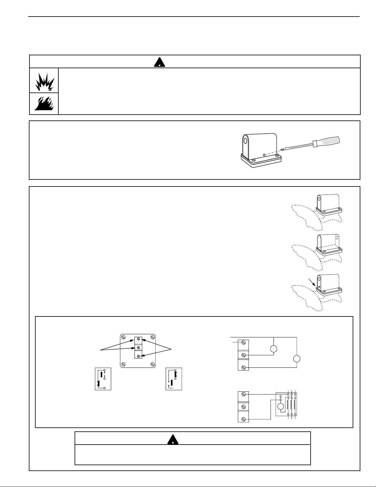
ELECTRICAL WIRING
TOOLS NEEDED:
One (1) flathead screwdriver.
Conduit opening facing
toward float chamber
Conduit opening facing
away from float chamber
Manual reset button
on No. 2m Switch
a. The No. 2 switch can be positioned with the conduit opening
facing toward or away from the float chamber. These are the
only positions in which the switch will function properly.
See drawing at right.
b. On initial fill-up, push the 2M manual reset button after the
proper water level is reached to energize the burner. If a
low water condition occurs and the water level has been
restored, push the reset button to energize the burner.
c. Follow the wiring diagrams below to wire the No. 2 Switch.
Terminals C and NC are the low water cut-off switch.
Terminals C and NO are alarm switch. If the electrical load
exceeds the rating of the switch, use an auxiliary relay or
motor starter.
USED AS A MAIN LINE SWITCH
AND/OR LOW WATER ALARM
USED AS A PILOT SWITCH TO COIL
OF RELAY OR MOTOR STARTER
N.
O.
N.C.
C.
N. O.
N.C.
C.
Neutral
120 V.A.C.
Supply Hot
Low
Water
Alarm
Burner
Circuit
Line
Load
SCHEMATIC OF SWITCH OPERATION
Water Level Normal
Burner On
Alarm Off
Low
Water
Alarm
Terminals
Low Water
Cut-Off
Terminals
C.
N.O.
N.C.
Water Level Low
Burner Off
Alarm On
C.
N.O.
N.C.
N.
O.
N.C.
C.
• To prevent electrical shock, turn off the electrical power before making electrical connections.
• This low water cut-off must be installed in series with all other limit and operating controls installed on the
boiler. After installation, check for proper operation of all of the limit and operating controls, before leaving
the site.
Failure to follow this warning could cause electrical shock, an explosion and/or a fire, which could result in
property damage, personal injury or death.
!
WARNING
Cover Removal and Installation Procedure
• Using a flathead screwdriver, remove the one
(1) screw that secures the switch cover.
• Place the cover on the switch housing and,
using a flathead screwdriver, tighten the one
(1) screw to approximately 2 ft•lb (2.6 N•m).
Do not use automatic water feeders with manual reset LWCO’s.
Failure to follow this warning could cause flooding, property damage, personal injury or death.
!
WARNING
Page 6

6
TROUBLESHOOTING
TESTING
Problem:
1. Burner does not shut off on low water.
a. Cause: Float chamber is loaded with mud or
sediment.
Test: With water level below the control
check if terminals C and N.C. are open.
If not, remove switch and manually test
if terminals C and N.C. can be opened.
Solution: Open float chamber and clean. At this
time, check for a build-up of scale or
sediment between corrugations of the
bellows.
b. Cause: Contacts are fused together.
Test: Remove switch and operate manually to
verify proper switch operation.
Solution: Replace switch. Check electrical load
and make sure it is within the ratings
of the switch.
CUT OFF
LEVEL
TEST
OPENING
• Control can be tested on a hot water
boiler by gently inserting a screwdriver
or similar tool in the test opening below
the switch (see drawing) and lifting linkage
to cause float to drop, thereby simulating a
low water condition.
Page 7

7
MAINTENANCE
SCHEDULE:
• Blow down control as follows when boiler is in
operation:
Steam:
– Daily if operating pressure is above 15 psi.
– Weekly if operating pressure is below 15 psi.
Hot Water:
– Quarterly
• Disassemble and inspect annually. Replace the
low water cut-off if it is worn, corroded, or if
components no longer operate properly.
• Inspect the float chamber and equalizing piping
annually. Remove all sediment and debris.
• Replace head mechanism every 5 years.
More frequent replacement may be required when
severe conditions exist such as rapid switch cycling,
surging water levels, and use of water treatment
chemicals.
• We recommend head mechanism replacement
when the switch(es) no longer operate properly.
If you choose to replace the switch(es), order the
proper McDonnell & Miller replacement switch or
switch assembly and follow the Repair Procedure
provided.
More frequent blow-down may be necessary due to dirty
water and/or local codes.
NOTE
PROCEDURE:
1. Blow down the low water cut-off when the water
level is at its normal level and the burner is on.
Slowly open the blow down valve until it is fully
open and observe the water level fall in the gauge
glass. Close the valve after verifying that the pump
contacts have closed and the burner shuts off.
If this does not happen, immediately shut off
the boiler and correct the problem.
To prevent serious personal injury from steam
pipe blow down, connect a drain pipe to the
control opening to avoid exposure to steam
discharge.
Failure to follow this caution could cause
personal injury.
!
CAUTION
Page 8

Xylem
1) The tissue in plants that brings water upward from the roots;
2) a leading global water technology company.
We’re 12,500 people unified in a common purpose: creating innovative solutions
to meet our world’s water needs. Developing new technologies that will improve
the way water is used, conserved, and re-used in the future is central to our work.
We move, treat, analyze, and return water to the environment, and we help people
use water efficiently, in their homes, buildings, factories and farms. In more than
150 countries, we have strong, long-standing relationships with customers who
know us for our powerful combination of leading product brands and applications
expertise, backed by a legacy of innovation.
For more information on how Xylem can help you, go to www.xyleminc.com
Xylem Inc.
8200 N. Austin Avenue
Morton Grove, Illinois 60053
Phone: (847) 966-3700
Fax: (847) 965-8379
www.xyleminc.com/brands/mcdonnellmiller
McDonnell & Miller is a trademark of Xylem Inc. or one of its subsidiaries.
© 2013 Xylem Inc. MM-206F July 2013 Part No. 246746
 Loading...