

Page 1
Series 67 and 767
Low Water Cut-Offs
For Steam Boilers
INSTRUCTION MANUAL
MM-201H
Page 2
A
D
2
INST
ALLATION –
T
OOLS NEEDED:
One (1) tube cutter, one (1) pencil, one (1) flathead
screwdriver, one (1) adjustable wrench and two (2)
pipe wrenches.
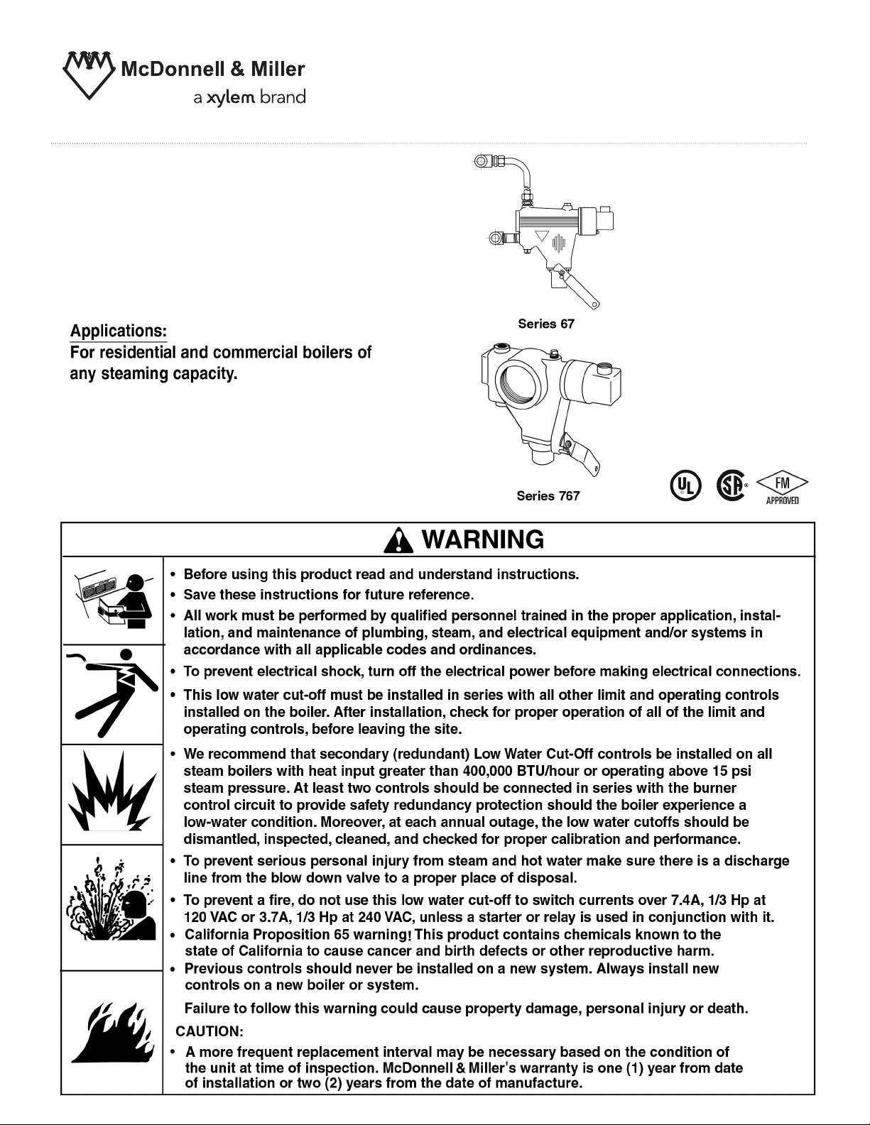
The Series 67 and Series 767 low water cut-offs are
float-type boiler controls designed to interrupt current
to the burner whenever the water drops to the cut-off
level.
The Series 767 is identical to Series 67 in all
respects except one. The Series 767 is equipped with
a 2-1/2" (63.5mm) pipe tap opening in the body, and
does not require the quick hook-up fittings supplied
with the Series 67. The pipe tapping allows for a
direct connection to the side of the boiler.
Electrical Ratings
Pump Circuit Rating (Amperes)
V
oltage Full Load Locked Rotor Pilot Duty
125 VA at
120 or 240 VAC
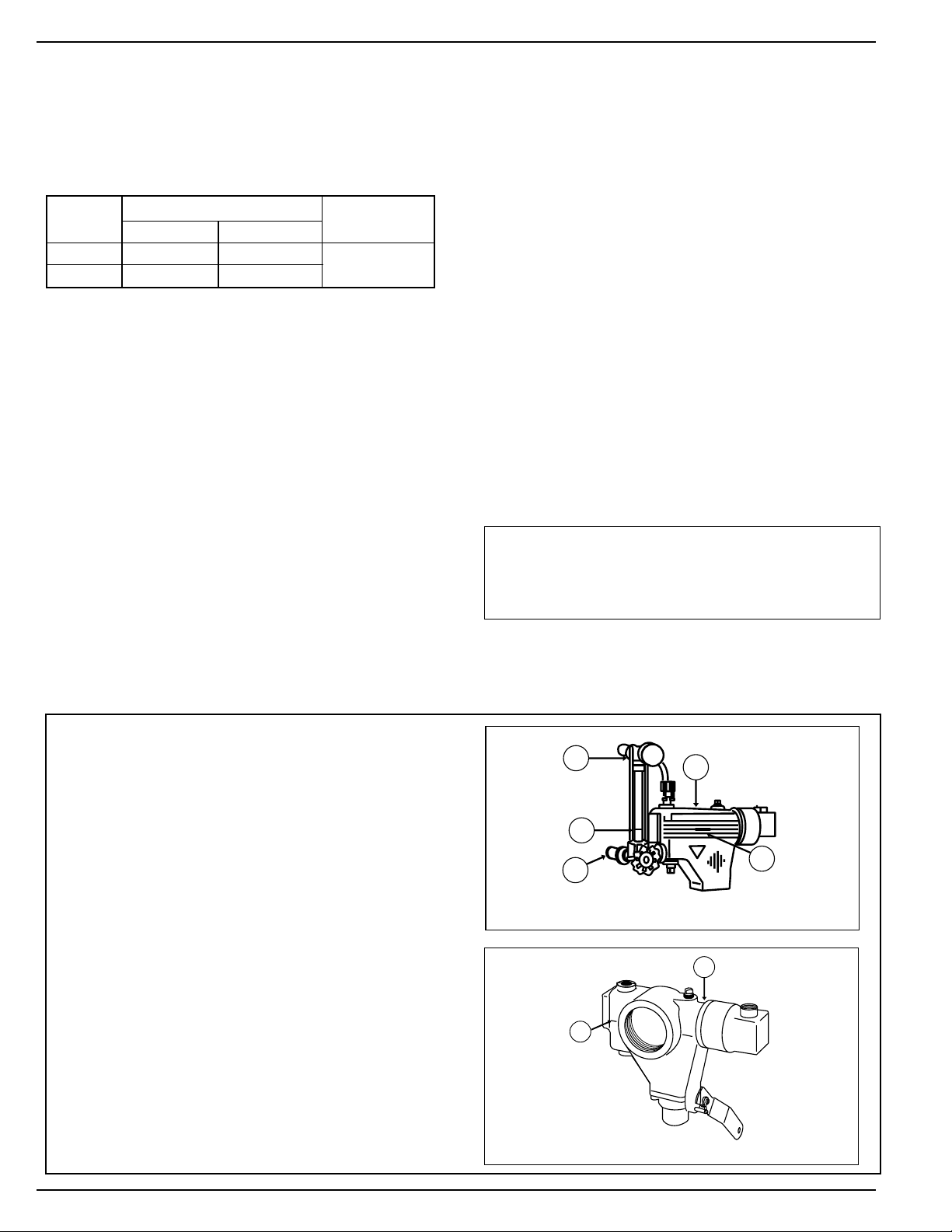
For Series 67 - The elevation of the control (A)
is already determined by the location of the
gauge glass tappings (B,C) on the boiler. The
horizontal cast line (D) should be located at or
above the boiler manufacturer's minimum safe
water level (E).
For Series 767 - The elevation of the control (A)
is already determined by the location of the 21/2 (63.5mm) pipe tapping on the boiler. The
horizontal cast line (D) of the body (A) should
be located at or above the boiler manufacturer's
minimum safe water level.
STEP 1 - Determine the Ele
vation at Which the
Low Water Cut-Off Controller Must be Installed
C
A
E
B
D
IMPOR
TANT: Follow the boiler manufacturer's
instructions along with all applicable codes and
ordinances for piping, blow down valve and water
gauge glass installation.
OPERA
TION
Maxim
um Steam Pressure: 20 psi (1.4 kg/cm
2
)
Series 67
Series 767
Note: 11 MV is rated at 24 V
A @ 24 VAC to 120 VAC
120 VAC
240 VAC
7.4
3.7
44.4
22.2
Page 3
3
a. Turn the boiler off.
b. Drain the water in the boiler to a level which
is below the lower gauge glass tapping (B)
of the control body (A). Allow the boiler to
cool to 80˚F (27˚C) and allow the pressure
to release to 0 psi (0 bar).
STEP 2 - Preparation
OFF
ON
AA
B
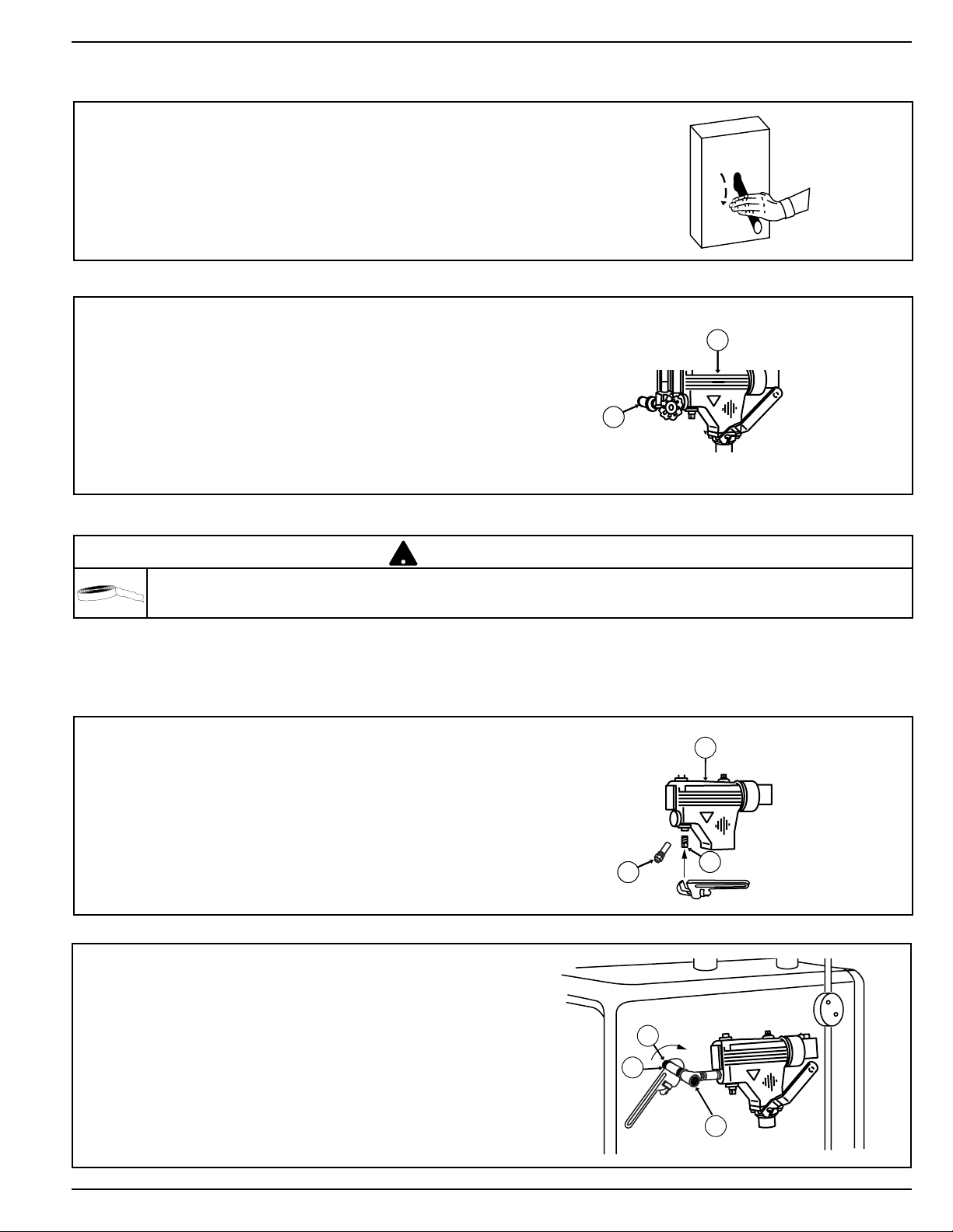
a. Using a pipe wrench, remove the float blocking
tube (F) from the new control and tighten a 2"
(13mm) NPT pipe plug (G) (provided) into the
tapping on the bottom of the control body (A).
Tighten the pipe plug to 31 ft•lb (42 N•m).
A
F
G
When using the tape sealant on the external threads of pipes or fittings, follow the manufacturers instructions. Use
sparingly and do not place on the first thread.
!
CAUTION
STEP 3 - Installing the New Low Water Cut-Off
b. Using a pipe wrench, install a 2" (13mm)
nipple (H) into the lower gauge glass tapping
(B) and pipe tee assembly (J). Tighten both
connections to 31 ft•lb (42 N•m).
J
B
H
Page 4
c. Using an adjustable wrench, install a a"
(9.5mm) NPT compression fitting base (K)
to the upper tapping (L) in the control (A).
Tighten to 31 ft•lb (42 N•m).
A
L
K
N
M
d. Using a pipe wrench, install a 2" (13mm)
nipple (M) into the upper tapping (N).
Tighten to 31 ft•lb (42 N•m).
e. Using a pipe wrench, install the pipe tee (P)
(provided) onto the nipple (M) in the upper
tapping (N). Tighten to 31 ft•lb (42 N•m).
N
M
P
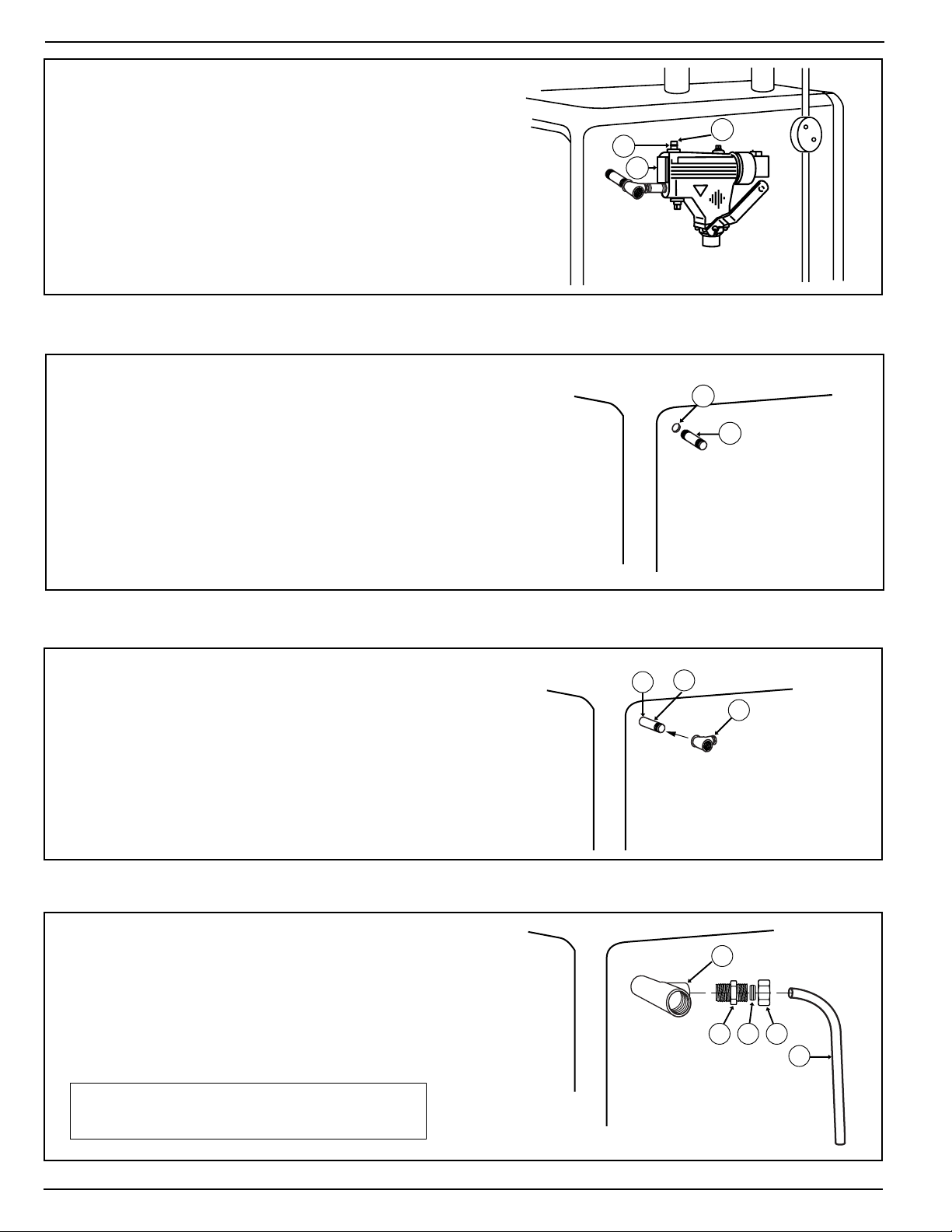
f. Using an adjustable wrench, install 1/2 (13mm) NPT
compression fitting base (U) into the upper tee (P).
Tighten to 31 ft•lb (42 N•m). Place the compression nut
(R) and compression ring (S) over the top of tubing (Q).
Insert tubing (Q) into compression base (U). Turn
compression nut (R) hand tight. DO NOT TIGHTEN.
IMPORTANT: Do not use tape or pipe
sealant on the compression fittings.
Q
U S R
P
4
Page 5

h. Insert the tubing (Q) into the upper compres-
sion fitting (U) and tighten the fitting to 31 ft•lb
(42 N•m).
U
Q
g. Position the tubing (Q) next to the compression
fitting (K) and, using a pencil, mark the tubing
(Q) for proper insertion into the compression
fitting (K).
Remove the tubing (Q), and, using the tube
cutter, cut the tubing to its proper length.
Q
K
5
i. Using two (2) pipe wrenches, rotate the upper
tee (P) counterclockwise and the lower tee (J)
clockwise.
j. Place the compression nut (R) and the compres-
sion ring (S) over the bottom of the tubing (Q).
P
J
Q
S
R
Page 6

k. Using two (2) pipe wrenches, rotate the upper
tee (P) clockwise and the lower tee (J) counterclockwise so that the end of the tube can be
inserted into the lower compression fitting (K).
NOTE: Make sure that the control is in a horizontal position. Using an adjustable wrench,
tighten the lower compression fitting (K) to
31 ft•lb (42 N•m).
K
J
P
6
T
U
V
l. Using a pipe wrench, install a w" (19mm) NPT
pipe (T) into the opening of the blow down
valve (U) and tighten to 47 ft•lb (64 N•m).
A
W
m. Hang the blow down card (W) (enclosed) as
close to the control (A) as possible, or
remove the protective backing and affix the
card on the boiler jacket close to the control.
X
a. Using a pipe wrench, install a 22" (63.5mm)
nipple (X) into the side of the boiler. Tighten
to 109 ft•lb (148 N•m).
For Series 767
To prevent burning or scalding, pipe blow-off
discharge from blow-down valve to floor –
allowing enough height for a pail under discharge pipe to collect blow down discharge.
This pipe must be same 3/4” size as blowdown connection; do not reduce. Do not
thread end of pipe.
!
CAUTION
Page 7

7
T
U
A
W
c. Using a pipe wrench, install a w" (19mm) NPT
pipe (T) into the opening of the blow down
valve (U) and tighten to 47 ft•lb (64 N•m).
A
b. Install the control (A) by rotating it onto the 22"
(63.5mm) nipple (X, as shown in Step a on
previous page). Tighten to 109 ft•lb (148 N•m).
d. Hang a blow down card (W) (enclosed) as
close to the control (A) as possible, or remove
the protective backing and affix the card on
the boiler jacket close to the control.
To prevent burning or scalding, pipe blow-off
discharge from blow-down valve to floor –
allowing enough height for a pail under discharge pipe to collect blow down discharge.
This pipe must be same 3/4” size as blowdown connection; do not reduce. Do not
thread end of pipe.
!
CAUTION
Page 8

STEP 4 - Electrical Wiring
Directory: 67 Low Water Cut-Off and Uni-Match Water Feeder page 8 - 9
67 Low Water Cut-Off and 101 Water Feeder page 10 - 11
For 67 Low Water Cut-Off Installed with McDonnell & Miller Uni-Match Water-Feeder
WARNING
!
• To prevent electrical shock, turn off the electrical power before making electrical connections.
• This low water cut-off must be installed in series with all other limit and operating controls installed on the
boiler. After installation, check for proper operation of all of the limit and operating controls, before leaving
the site.
Failure to follow this warning could cause electrical shock, an explosion and/or a fire, which could result in
property damage, personal injury or death.
a. Using a flathead screwdriver, remove the one
(1) screw that secures the low water cut-off
switch cover (Y).
b. Using a flathead screwdriver, loosen the two
(2) screws and remove the feeder cover (Z).
Y
Z
c. Position the slide switch selector (AA) in the
position.
8
AA
Page 9

Page 10

NOTE: To connect wires to the terminals
on the burner, or low water cut-off, place
the bare end of the wire under the terminal
screw and tighten the screw with a flathead screwdriver. On the 101-A water
feeder use wire nuts.
Y
a. Using a flathead screwdriver, remove the one
(1) screw that secures the low water cut-offs
switch housing (Y).
BB
b. Using a flathead screwdriver, remove the
two
(2) screws that secure the feeder cover
(BB).
For 67 Low Water Cut-Off Installed with McDonnell & Miller Series 101-A Water-Feeder
For the 120V Burner/120V Feeder setups.
BURNER
120 VAC
SUPPLY
12
34
N
H
101A
69
c. Using a wire nut, connect a wire from the
neutral side of the power supply to one of
the wires inside the feeders junction box.
(Does not make a difference which one).
Connect a wire from the "hot" side of the
power supply to terminal #2 of the Series 67
junction box. Connect the neutral side of the
power supply to the burner.
BURNER
120 VAC
SUPPLY
12
34
N
H
101A
d. Connect the wire from the burner to terminal
#1 of the low water cut-off. Connect a
"jumper" from terminal #2 to terminal #3 of the
low water cut-off. Connect a wire from terminal #4 of the low water cut-off to the remaining wire in the 101A water feeder.
10
Page 11

For the 24V Burner/24V Feeder setups.
BURNER
101A-24
120 VAC
SUPPLY
24V TRANSFORMER
(101-24V-48)
12
34
N
H
24V
69
c. Connect the "hot" wire from the boiler trans-
former to terminal #2 of the low water cut-off.
Connect the "hot" side of the water feeder
transformer to terminal #3 of the low water
cut-off. Connect the neutral side of the boiler
transformer to the burner. Using a wire nut,
connect the neutral side of the water feeder
transformer to the water feeder.
BURNER
101A-24
120 VAC
SUPPLY
24V TRANSFORMER
(101-24V-48)
12
34
N
H
24V
d. Connect the wire from the burner to terminal
#1 of the low water cut-off. Connect a wire
from terminal #4 of the low water cut-off to the
remaining wire in the water feeder. Wire nut
together.
BURNER
101A
120 VAC
SUPPLY
N
H
24V
12
34
69
Wiring Alternative
For the 120V Burner/24V Feeder setups. For the 24V Burner/120V Feeder setups.
BURNER
101A-24
120 VAC
SUPPLY
24V TRANSFORMER
(101-24V-48)
TO AVOID DAMAGE TO 101A
SOLENOID COIL, TRANSFORMER
101-24V-48 MUST BE USED.
N
H
12
34
69
11
IMPORTANT: It is very important that you use the transformer supplied with the 101-A-24. The boiler
transformer in most cases is not big enough to handle the current draw of the 101-A-24.
Use the supplied transformer (101-24-48). In most cases it will handle both the boiler
and feeder. Do not try to use two transformers in the same circuit.
Page 12

For All Installations
The BX outlet (GG) on the control is mov
able
into any of the four positions by simply
removing the two black-headed screws and
rotating the housing.
BOTTOM TOP LEFT RIGHT
ALLA
INST
MAINTENANCE
SCHEDULE:
• Blo
w down weekly (at least once) when the
boiler is in operation.
• Disassemble and inspect annually. Replace
the low water cut-off if it is worn, corroded,
or if components no longer operate properly.
• Inspect the float chamber and equalizing
piping annually. Remove all sediment
and debris.
• Replace every 10 years. More frequent replace-
ment may be required when severe conditions
exist such as rapid switch cycling, surging water
levels, and use of water treatment chemicals.
TION COMPLETE
PROCEDURE:
To
prevent serious personal injury from steam and hot
water, make sure there is a discharge line from the
blow down valve to a proper place of disposal.
Failure to follow this caution could cause
personal injury.
1. Blo
w down the low water cut-off when the
water level is at its normal level and the
burner is on. Fully open the blow down
valve and observe the water level fall in the
gauge glass. Close the valve after verifying
that the feeder contacts have closed and
the burner shuts off. If this does not happen,
immediately shut off the boiler and correct
the problem.
CAUTION
!
Xylem Inc.
8200 N.
Morton Grove, Illinois 60053
Phone: (847) 966-3700
Fax: (847) 965-8379
www.mcdonnellmiller.com
McDonnell & Miller is a trademark of
© 2014 Xylem Inc. MM-201H March 2014 Part No. 246752
Austin Avenue
Xylem Inc. or one of its subsidiaries.
 Loading...