

Page 1
INSTRUCTION MANUAL
IM253 R0
AquaStart
COMBINATION SOFT STARTERS
START-UP MANUAL
™
Page 2

INDEX
Power Connections ................................................................................................................................................................ 3
Basic Wiring ............................................................................................................................................................................ 4
Start-Up By Voltage Ramp ....................................................................................................................................................5
Local / Remote Modes ..........................................................................................................................................................6
Control and Signal Connections ..........................................................................................................................................6
Control Wiring Terminals ......................................................................................................................................................7
Connections for Remote Start/Stop ....................................................................................................................................8
Control via 2-Wire Start / Stop (Remote Mode) .................................................................................................................9
Control via 3-Wire Start / Stop (Remote Mode) ...............................................................................................................10
Programming via DIP Switches and Trim Pots ..................................................................................................................10
Parameters Example ............................................................................................................................................................11
Minimum Trim Pots and DIP Switches to Set ....................................................................................................................12
Current Limiting for Loads with High or Constant Starting Torque ...............................................................................13
Soft Starter Operation .........................................................................................................................................................14
Fault Codes ...........................................................................................................................................................................14
Limited Warranty ..................................................................................................................................................................16
2
Page 3
POWER CONNECTIONS
The AquaStart Start-up Manual is a supplement to help get the AquaStart commissioned quickly using the
most common installation and conguration options. This manual is not meant to replace the SSW07 User’s
Manual. For detailed safety precautions, mounting, installation, conguration, or operation instructions, please
refer to the SSW07 User’s Guide.
WARNING: Only qualied personnel should plan or implement the installation, start-up, operation and
maintenance of this equipment. Personnel must read the entire SSW07 User’s Guide before attempting to
install, operate or troubleshoot the AquaStart Panel.
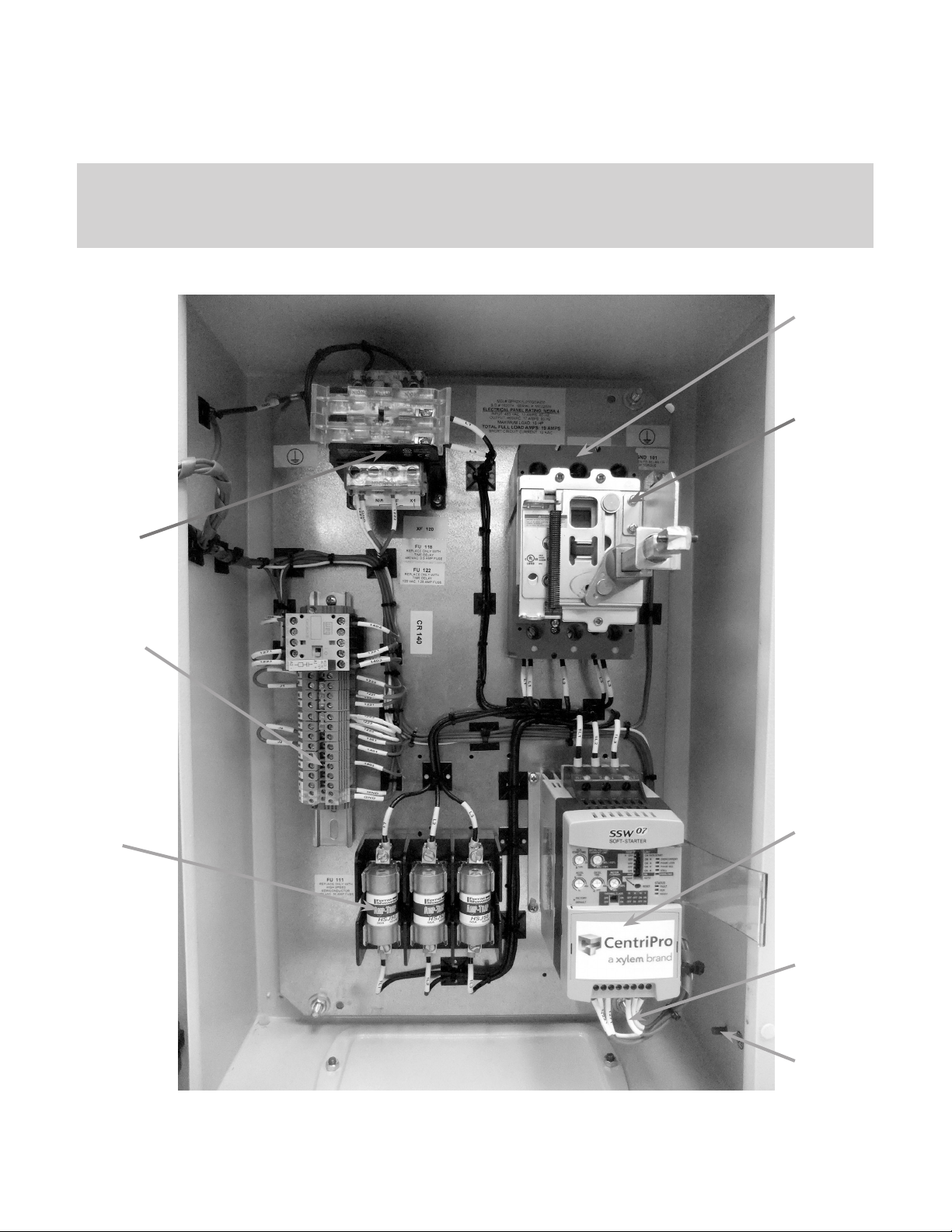
Input
Supply
Power
Fusible
Disconnect
Control
Power
Transformer
Control
Wiring
Terminals
Fuse
Block
SSW-07
Soft
Starter
Output
FIGURE 1 – Panel Internal Layout
Power
to Motor
Ground
(M6
thread)
3
Page 4
BASIC WIRING
1. Mount the AquaStart panel to a at vertical surface.
2. Connect the three-phase incoming power leads to the R, S, and T connections on the power terminal (refer
to Figure 1). Connect the motor leads to the U, V, and W connections on the power terminal and connect
the GROUND lead to PE on the chassis (refer to Figure 1). Note: Only three-phase AC motors can be
used.
USING THE KEYPAD (OPTIONAL)
The keypad can be used in the following arrangements:
• Keypad on controller:
o Local keypad is attached to the SSW07 controller for commanding, programming, and/or visualizing
parameters.
• Keypad on door:
o Remote keypad is mounted “through door” attached to the SSW07 controller with a cable for
commanding, programming, and/or visualizing parameters.
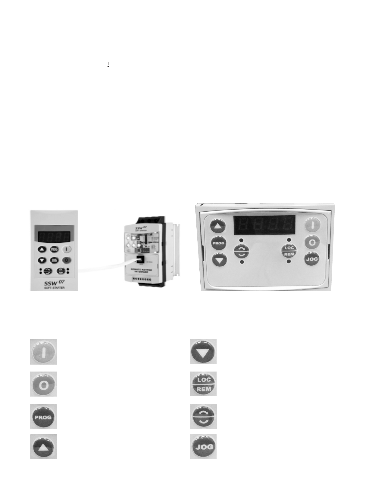
The SSW-07 local or remote keypads present a 7-segment 4-digit LED display, 4 status LEDs, and 8 keys. The
gures below show a front view of the remote keypad and the local keypad.
REMOTE KEYPAD LOCAL KEYPAD FRONT VIEW
FIGURE 2 – Keypads
BASIC FUNCTIONS OF THE KEYS:
Enables the motor (start);
Disables the motor (stop), Resets the
Soft-Starter after the occurrence of
errors;
Selects (toggles) the display between
the parameter number and its value
(position/content);
Increments the parameter number or
parameter value;
4
Decrements the parameter number or
parameter value;
Selects the origin of the commands
between Local or Remote;
No Function on SSW-07
No Function on SSW-07
Page 5
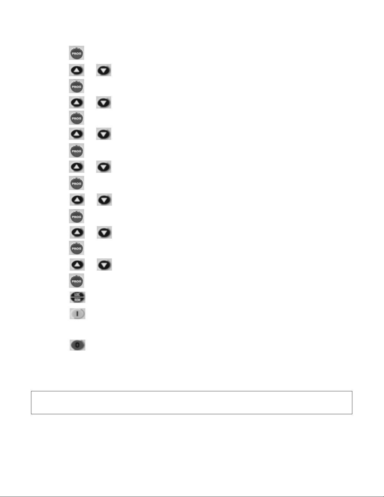
START-UP BY VOLTAGE RAMP USING THE KEYPAD: (most common conguration)
1. The soft starter should be powered up with a display of “RDY”.
2. Press the key to enter the programming mode.
3. Press the or key to select P000 (Access to parameters).
4. Press the key to change value of parameter.
5. Press the or key to set to “5” to allow access to parameters.
6. Press the key to save the selected option.
7. Press the or key to select P219 (Parameterization via keypad).
8. Press the key to change value of parameter.
9. Press the or key to set to “0” for keypad programming.
10. Press the to save the selected option.
11. Press the or key to select P202 (the Password is).
12. Press the key to change value of parameter.
13. Press the or key to set to “0” for Voltage Ramp.
14. Press the key to save the selected option and exit the programming mode.
15. Press the or key to select P003 (Motor Current).
16. Press the key to read the Motor Current value (This is a read parameter).
17. Press the key to operate soft-start via HMI.
18. Press the start key. The motor accelerates to full voltage and the bypass contact engages.
Note: If the direction of rotation is not correct, turn the input disconnect to the off position and swap any
two wires at the motor output.
19. Press the stop key. The motor decelerates until stopping by coast to rest. Time to stop depends on
load inertia and friction.
Note: For a complete description of Parameters and Error codes refer to Chapters 6 and 7 in the SSW07
Programming Manual.
NOTE: FOR SUBMERSIBLE MOTORS, SET THE INITIAL VOLTAGE P101 TO 70% AND THE MOTOR
PROTECTION THERMAL CLASS P640 TO 2 (CLASS 10).
5
Page 6

LOCAL/REMOTE MODES (Optional Keypad):
In the previous section the soft starter was operated from the keypad (Local Mode). Note the green local
indicator LED on the bottom right of the keypad. For the factory default programming, the selection of the
operation mode (Local/Remote) is made via the “Local/Remote” key (default is Remote). Pressing of the “Local/
Remote” will alternate operation between local & remote. Notice the indicator switches from the green to
the red indicator LED when “Local/Remote” is pressed. If you wish to use an external Local/Remote switch set
P220=4, connect the switch to one of the Digital Inputs (DI1-DI3), and set the corresponding parameter (P263
to 265=2).
To always run in Local mode set P220=0.
To always run in Remote mode set P220=1.
CONTROL AND SIGNAL CONNECTIONS:
Control and signal connections (digital inputs and relay outputs) are made through the terminals (see Figure 3).
Terminal Description Specications
A1
Electronics Supply
A2
Terminal Factory Default Specications
DI1 Starts/Stops Motor
DI2 Fault reset
DI3 Fault reset
13 Relay 1 output - Operation
14 / 23 Relay common point
24 Relay 2 output - Full voltage
FIGURE 3 – SSW-07 Control and Signal Connections
6
Voltage: 110 to 240 Vac (-15% a +10%)
Current: 140mA Maximum
(factory connections)
3 isolated digital inputs
Voltage: 110 to 240 Vac (-15% a +10%)
Current: 2 mA Maximum
Contact capacity:
Voltage: 250Vac
Current: 1A
Torque Nm
(in lb)
0.5 (4.5)
Page 7

CONTROL WIRING TERMINALS
CONTROL WIRING TERMINAL STRIP
Control Relay
ES1
ES2
1221
1221
1223
1223
1301
1401
1441
1403
SP
SP
GND
GND
FIGURE 4 – Control Wiring Terminals
SSW 07
Terminals
A1 1221
A2 1223
13 1301
Control
Terminal
Label
ES1
ES2
1221
1223
1401
1441
1403
SP
SP
Control Terminal
Description
Safety/Emergency Stop*
Connected by J1. To enable an
emergency stop function, re-
move J1 and install the control
device between ES1 and ES2
110Vac Control Voltage
Neutral for Control Voltage
Connected to 1401 by J2.
J2 Enables Start and Stop
Buttons on enclosure cover.
To disable buttons on the cover,
remove J2. To add a remote
Start/Stop, connect a jumper
from 1301 to 1441 and wire the
control device between 1441
and 1403.
Connection to Start and Stop
Buttons on enclosure cover.
Remote Start/Stop**
Spares
CONNECTIONS FOR REMOTE START/STOP
* Emergency Stop
A Safety or Emergency Stop function can be implemented
by removing the J1 jumper connecting terminals ES1
and ES2. The emergency stop device will then be wired
between ES1 and ES2. When an emergency situation
(high pressure, high temperature, …) is encountered the
device must open to disconnect control power to the
circuitry enabling the soft starter. This will then stop the
pump/motor. This control device must be sized to operate
at 2.5A at 115Vac.
CAUTION! THE EMERGENCY STOP DEVICE DOES
NOT DISCONNECT LINE POWER TO THE SOFT
STARTER.
GND
Ground
GND
7
Page 8

CONNECTIONS FOR REMOTE START/STOP
** Remote Start/Stop
A Remote Start/Stop function can be implemented to
allow control of the soft starter by an external control
device (pressure switch, ow switch, …). To implement
a remote start/stop, remove the J2 jumper connecting
terminals 1301 and 1401. Then connect a jumper wire
from 1301 to 1441. The control device will then be
connected between 1441 and 1403. When the control
device is open, the soft starter will stop the pump/
motor. When the control device is closed, the soft
starter will start the pump/motor. This control device
must be sized to operate at 2.5A at 115Vac.
CAUTION! WHEN J2 IS REMOVED, THE START AND
STOP BUTTONS ON THE FRONT OF THE PANEL ARE
DISABLED.
8
Page 9

CONNECTIONS FOR REMOTE CONTROL OF THE SSW07 WHEN PURCHASED SEPARATELY
CONTROL VIA 2-WIRE START/STOP
(Remote Mode):
FIGURE 5 – Control via 2-wire Start/Stop
Control Wiring: Start/Stop switch is N.O.
(Normally Open) and is wired as shown in Figure 4.
Parameters (Optional Keypad):
1. Set P220 = 1 Always Remote
2. Set P230 = 1 Digital Inputs
3. Set P263 = 1 DI1 Enable/Disable
CONTROL VIA 3-WIRE START/STOP
(Remote Mode):
FIGURE 6 – Control via 3-wire Start/Stop
Control Wiring: “Start” and “Stop” are momentary push button switches and are connected as shown in
Figure 4. “Start” is a N.O. (Normally Open) contact and “Stop” is a N.C. (Normally Closed) contact.
Parameters (Optional Keypad):
1. Set P220 = 1 Always Remote
2. Set P230 = 1 Digital Inputs
3. Set P263 = 1 DI1 Start (three wires)
4. Set P264 = 1 DI2 Stop (three wires)
9
Page 10
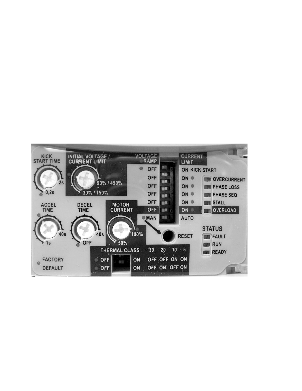
PROGRAMMING VIA DIP SWITCHES AND TRIM POTS:
To program DI2 for 3-wire control, refer to Figure 5 and perform the following:
1. Press and hold the reset button on the front of the SSW07 for 5 seconds to enter the programming mode.
Note: The reset button must remain pressed during programming.
2. When the programming mode is entered, two LED’s will illuminate (over-current and phase loss), indicating
that DI2 is programmed for fault reset.
3. To re-program for 3-wire control, switch the over-current dip-switch and return to the previous position.
Three LED’s will illuminate (over-current, phase loss, and phase sequence), indicating that DI2 is now
programmed for 3-wire control.
4. To change DI2 programming back to fault reset, switch the kick start dip-switch and return to the previous
position. Two LED’s will illuminate (over-current and phase loss), indicating that the DI2 is programmed for
fault reset.
5. Release the reset button to complete the programming.
FIGURE 7 – Trim-Pots and Dip Switch Locations
10
Page 11

PARAMETERS EXAMPLE (Optional Keypad) (P219 = 1):
Soft Starter Data (Example):
Enclosure Model: AST40150
SSW-07 Model: SSW07XY0024T5SZ
Motor Data (Example):
Power: 15 HP
Rated Speed: 3450 RPM
Motor FLA Current: 21A
Service Factor Current: 24A
Rated Voltage: 460 V
Service Factor: 1.15
The following is a typical list of parameter changes needed using the Motor/Soft Starter data shown above.
P000=5 Parameter Access (5 = Password)
P219=1 Parameterization via keypad/ (trim pots and DIP switches) (1 = keypad)
P202=0 Type of Control (0 = Voltage Ramp)
P101=50 Initial Selected Voltage (50%)
P102=20 Voltage Ramp Time (20 seconds)
P400=460 Motor Rated Voltage (460 volts)
P401=87.5% Motor Rated Current (21 amps)
P406=1.15 Motor Service Factor (1.15)
P640=6 Thermal Motor Protection Class (Class 30)
Local/Remote parameters allow the soft starter to be set up to operate from Keypad, Remote Terminal, or a
programmed combination of keypad and terminal inputs.
P220 – Local/Remote Selection
P229 – Local Status Command
P230 – Remote Status Command
Read Only Parameters (P001 – P081) can be used for monitoring and troubleshooting. For a full list and
description please read the SSW07 Programming Manual. By monitoring certain read only parameters, the
status of inputs, outputs, and soft starter operational values can be determined without the use of any other
test equipment.
P003 - Motor Current
P006 - Soft Starter Status
P007 - Output Voltage
P012 - Digital Input Status
P013 - (Relay Output Status) – used to monitor relay outputs.
11
Page 12
TRIM-POT AND DIP SWITCH SETTINGS (P219 = 0):
Soft Starters are shipped with factory default values. If Trim-Pots and Dip Switches have been changed, it
is advisable to reset to factory default positions prior to a new installation by aligning all trim-pots and dip
switches with the red factory default dots. By default the control type is Voltage Ramp Starting. This control
type is very easy to setup and is the most commonly used starting method. Current Limit Starting is the
second control type and is described below.
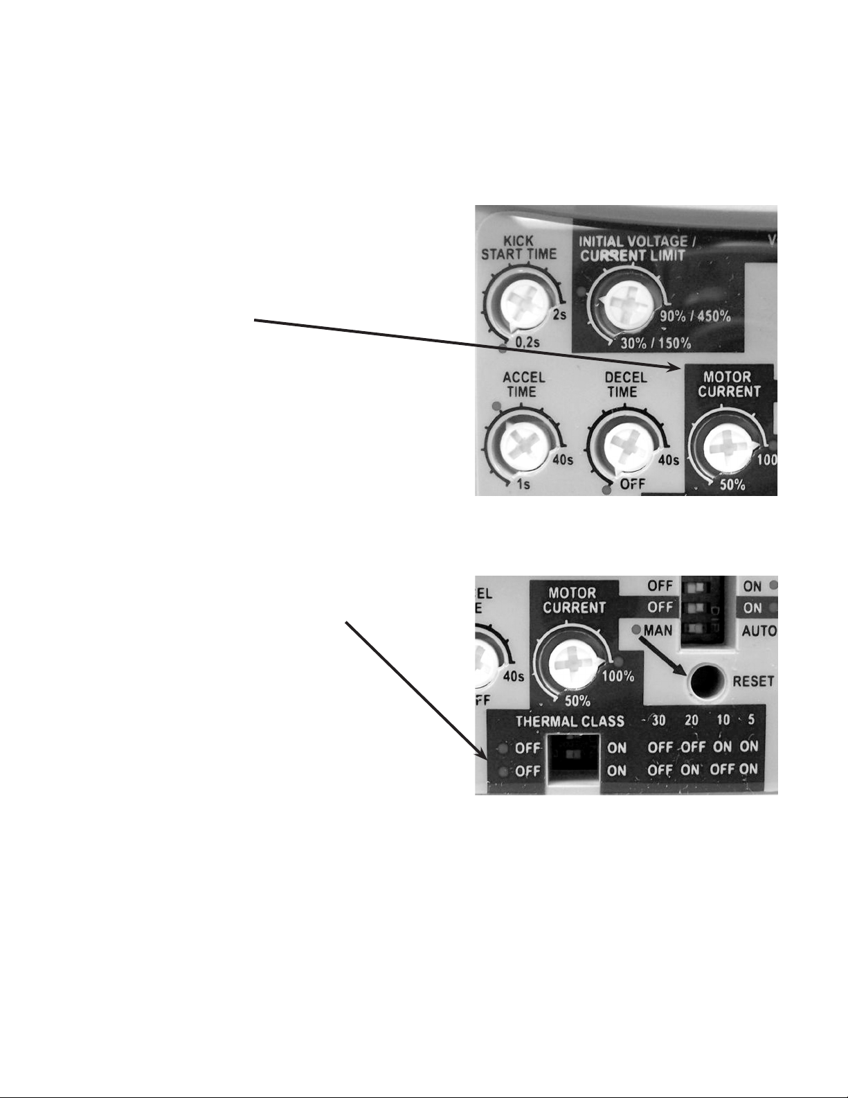
Motor Current Trim-Pot Setting - Factory default position is
100% and is marked with a red dot. To protect the motor from
overload, obtain the full load amperage (FLA) off the motor
and soft-starter name plates. Using the following formula,
calculate the percentage of current that the motor will draw
from the soft-starter and set the Motor Current Trim-Pot
accordingly.
– Max A of the soft-starter = 170A
– Max A of the motor = 140A
– Max A of the motor / Max A of the switch
= 140A / 170A = 0.823
– Motor Current Trim-Pot = 82.3%
Thermal Class Dip Switch Setting – Set to factory default of
30 if not specied on the motor name plate. (Note: Factory
default positions are marked with red dots).
Note: If using a submersible motor, set the
thermal overload class to class 10.
Note: These are the minimum settings for a
perfect adaptation between soft starter and motor.
For a complete description of Trim-Pot and Dip Switch
settings refer to Chapter 4 in the SSW07 User’s Guide.
Figure 8 - Motor Amp Trim-Pot
Figure 9 - Thermal Class Dip Switch
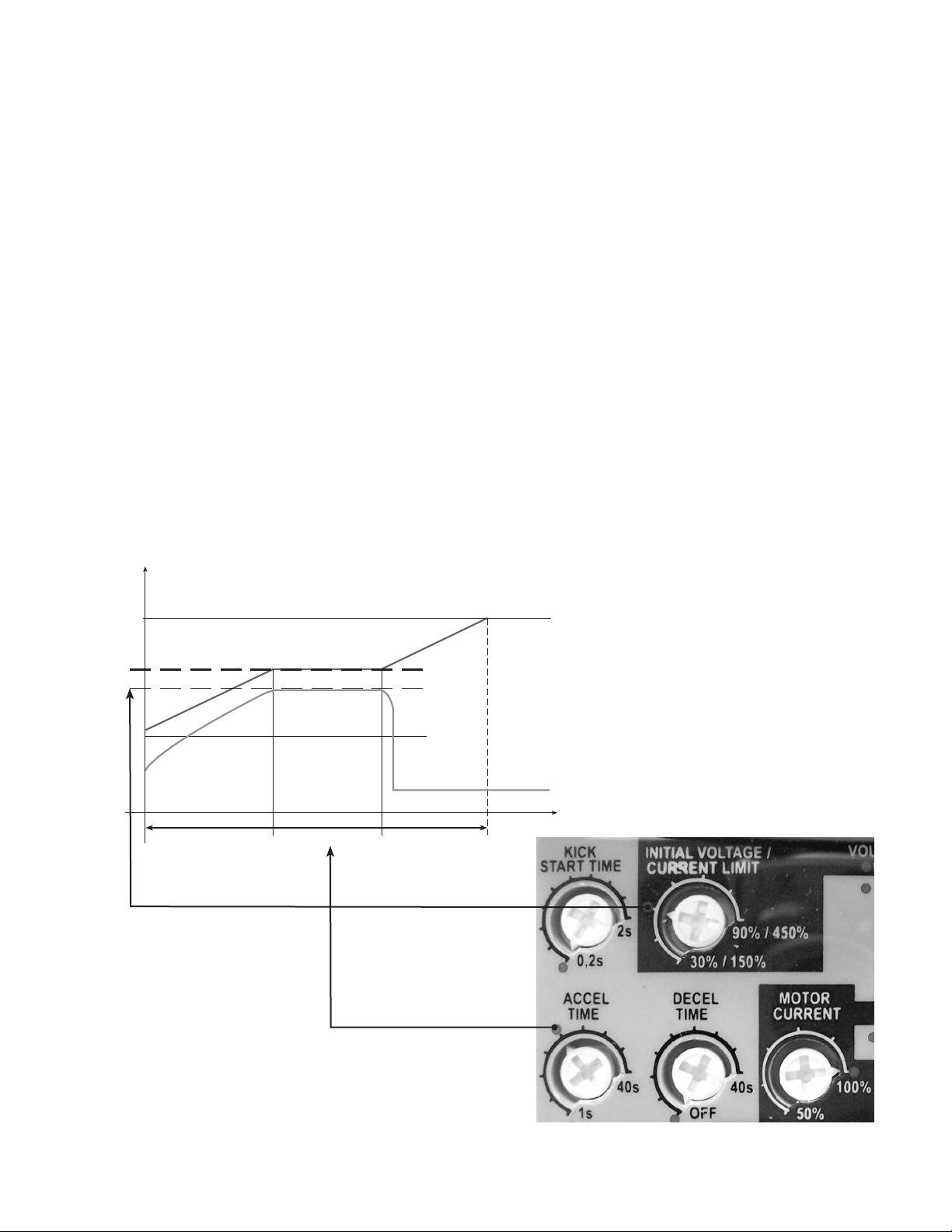
Initial Voltage/Current Limit Setting - When operating in Voltage Ramp Starting mode, this setting
congures the initial voltage applied to the motor during start up. When using a submersible motor, set the
initial voltage to 70% to ensure the motor accelerates to half speed in 1 second. For other motor types, set the
voltage so that the motor begins to spin as soon as a start command is given to the soft starter.
Accel Time Setting - When operating in Voltage Ramp Starting mode, this setting controls the time of the
voltage ramp. This is the time from the start of the ramp (initial voltage) to soft starter bypass. This is not the
motor acceleration time. For a faster start, decrease this setting. For a slower start, increase this setting.
12
Page 13
CURRENT LIMITING FOR LOADS WITH HIGH OR CONSTANT STARTING TORQUE:
Current limiting control is used to adapt the Soft Starter to the capacity limits of the power supply. It is often used
with power generators with limited output but may also be used to keep current draw to a minimum on loads
with high or constant starting torque.
Optional Keypad:
1. Set P202 = 1 Type of control = Current Limit
2. Set P110 to % of current you wish to limit using example below.
3. Set P102 to desired acceleration.
Trim-Pot and Dip Switch Settings (Figure 9):
1. Set the Voltage Ramp/Current Limit dip switch to the Current Limit position.
2. Set the Current Limit Trim-Pot using the following example.
Calculation example for limiting the current to 2.5 x IN of the motor:
– IN of the switch = 60A
– IN of the motor = 52A
– ILIM = 250% of the IN of the motor
– 2.5x 52A =130A
– 130A / IN of the switch = 130A / 60A = 2.17 x IN of the switch
– Current Limit = 217% of the IN of the switch = 2.5x IN of the motor
U
100 %
fixed voltage
Figure 10 - Current Limiting
current limit
Accel Time
reached set level
of current limit
Time
Notes: (1) The Current Limit must be set at a level that permits
the motor to accelerate otherwise the motor will not start. (2)
If the full voltage is not reached at the end of the acceleration
ramp time an E62 error will occur and the motor will be
disabled. For details on Fault Codes please refer to Chapter 6 in the SSW07 User’s Guide. (3) For details on
Current Limiting please refer to Chapter 5 in the SSW07 User’s Guide.
13
Page 14

SOFT STARTER OPERATION:
The Soft Starter is now ready to operate via the 2-Wire or 3-Wire Control that was set up in the previous steps.
To start the motor, press the “Start Button” and the Soft Starter will accelerate up to speed (default acceleration
time is 20sec). When full voltage is reached the internal bypass contactors will engage and switch the motor to
the supply line.
To stop the motor, press the “Stop Button” and the Soft Starter will decelerate to the stop position (default
deceleration time is “Off” so the motor will coast to rest). For details on setting deceleration time and other trim-
pots refer to Chapter 4 in the SSW07 User’s Guide.
FAULT CODES:
Optional Keypad:
When a fault is detected, the Soft Starter is disabled and the Fault Code is displayed (example E03). To restart
the Soft Starter after a fault has occurred, the Soft Starter must be reset. Resetting the Soft Starter can be done
by disconnecting and reapplying AC power (power-off reset), by pressing the “O/RESET” key (manual reset),
automatic reset, or via digital inputs. For details on Reset and a full list and description of Fault Codes, please
read Chapter 6 in the SSW07 User’s Guide.
Trim-pots and DIP switches:
When a fault is detected, the Soft Starter is disabled and the Fault Code is displayed by ashing LED’s. To restart
the Soft Starter after a fault has occurred, the Soft Starter must be reset. Resetting the Soft Starter can be done
by disconnecting and reapplying AC power (power-on reset), by pressing the “RESET” button on the front panel
(manual reset), automatic reset, or via digital inputs. For details on Reset and a full list and description of Fault
Codes please read Chapter 6 in the SSW07 User’s Guide.
14
Page 15

NOTES
15
Page 16

LIMITED WARRANTY
This warranty applies to this Xylem Inc. product.
Any part or parts found to be defective within the warranty period shall be replaced at no charge to the dealer during the warranty period. The warranty period shall
exist for a period of thirty (30) months from date of installation or thirty-six (36) months from date of manufacture, whichever period is shorter.
A dealer who believes that a warranty claim exists must contact the authorized Xylem Inc. distributor from whom the equipment was purchased and furnish complete
details regarding the claim. The distributor is authorized to adjust any warranty claims utilizing the Xylem Inc. Customer Service Department.
The warranty excludes:
(a) Labor, transportation and related costs incurred by the dealer;
(b) Reinstallation costs of repaired equipment;
(c) Reinstallation costs of replacement equipment;
(d) Consequential damages of any kind; and,
(e) Reimbursement for loss caused by interruption of service.
For purposes of this warranty, the following terms have these denitions:
(1) “Distributor” means any individual, partnership, corporation, association, or other legal relationship that stands between Xylem Inc. and the dealer in purchases,
consignments or contracts for sale of the subject equipment.
(2) “Dealer” means any individual, partnership, corporation, association, or other legal relationship which engages in the business of selling or leasing equipment to
customers.
(3) “Customer” means any entity who buys or leases the subject equipment from a dealer. The “customer” may mean an individual, partnership, corporation, limited
liability company, association or other legal entity which may engage in any type of business.
THIS WARRANTY EXTENDS TO THE DEALER ONLY.
Xylem Inc.
2881 East Bayard Street Ext., Suite A
Seneca Falls, NY 13148
Phone: (800) 453-6777
Fax: (888) 322-5877
www.centripro.com
CentriPro and AquaStart are trademarks of Xylem Inc. or one of its subsidiaries.
© 2013 Xylem Inc. IM253 Rev. 0 September 2013
 Loading...