

Page 1

Model
H-3531 F lashLite™
Owner's Manual
Version 1.9
75 West 100 South, Logan, Utah 84321 Phone: (435) 753-2212 Fax: (435) 753-7669 Web: http://www.waterlog.com E-mail: waterlog@waterlog.com
D E S I G N A N A L Y S I S A S S O C I A T E S , I N C .
Page 2

Page 3

User Agreement/
WATERLOG Warranty
1. NATURE OF THE PRODUCT
This agreement accompanies a pressure measuring system comprising firmware, circuitry and other
electronic equipment in an enclosed housing, and packaged together with written instructional materials.
The packaged electronic circuitry and instructional materials herein are collectively referred to as the
“PRODUCT.” The PRODUCT is made available from DESIGN ANALYSIS ASSOCIATES, INC., of
75 West 100 South, Logan, Utah 84321 (hereinafter referred to as “DESIGN ANALYSIS”), and contains
information and embodies technology that is confidential and proprietary to DESIGN ANALYSIS, and
the availab ility and use of the PRODUCT is extended to you , the US ER, solely on t he basis of the ter ms
of agreement which follow.
2. ACKNOWLEDGMENTS BY USER
Opening the package which encloses the accompanying PRODUCT indicates your acceptance of the
terms and conditions of this agreement and constitutes an acknowledgment by you of the confidential and
proprietary nature of the rights of DESIGN ANALYSIS in the PRODUCT.
3. DUTIES OF YOU, THE USER
In cons idera tion f or the acces s to and use of the PRO DUCT extended to you by DESIGN ANALYSIS
and to protect the confidential and proprietary information of DESIGN ANALYSIS, USER agrees as
follows:
®
(a) USER agrees that they will not remove from the exterior of the housing of the
PRODUCT any safety warnings or notices of proprietary interest placed thereon by
DESIGN ANALYSIS.
(b) USER agrees that they shall not disassemble or otherwise reverse engineer the
PRODUCT.
(c) USER agrees to treat the PRODUCT with the same degree of care as USER exercises in
relation to their own confidential and proprietary information.
4. TERM
USER may enjoy these rights only as long as their possession of the PRODUCT shall continue to be
rightful. These rights will cease if the PRODUCT is returned to DESIGN ANALYSIS under the terms of
any redemption offer, warranty, or money-back guarantee, or if USER transfers the PRODUCT to
another party on terms inconsistent with this agreement.
5. LIMITED WARRANTY
(a) What is Covered
DESIGN ANALYSIS warrants that for a period of twelve months from the time of delivery the
functions to be performed by the PRODUCT will be substantially in compliance with USER
documentation. DESIGN ANALYSIS also warrants that the PRODUCT will be free from
defect s in materials and workmanship for a period of ONE YEAR from the date of del ivery.
H-3531 User Agreement/WATERLOG Warranty W-1
®
Page 4

(b) What USER Must Do
If the product fails to satisfy the above warranty, USER must notify DESIGN ANALYSIS in
writing within the applicable period specified above and reasonably cooperate with the directions
they received from DESIGN ANALYSIS.
(c) What DESIGN ANALYSIS Will Do
DESIGN ANALYSIS will repair the PRODUCT or will endeavor to provide a replacement of
same within a reasonable period of time. In the event that DESIGN ANALYSIS is unable to
make the necessary repairs or replacement within a reasonable period of time, the original
purchase price will be refunded upon the return of the PRODUCT to DESIGN ANALYSIS.
(d) Limitations
(i) THE ENTIRE REMEDY FOR BREACH OF THIS LIMITED WARRANTY
SHALL BE LIMITED TO REPLACEMENT OF THE DEFECTIVE PRODUCT
OR REFUNDING OF THE PURCHASE PRICE, AS SET FORTH ABOVE.
IN NO EVENT WILL THE LIABILITY OF DESIGN ANALYSIS TO USER
OR TO ANY OTHER PARTY EXCEED THE ORIGINAL PURCHASE PRICE
OF THE PRODUCT, REGARDLESS OF THE FORM OF THE CLAIM.
(ii) EXCEPT FOR THE EXPRESS WARRANTIES ABOVE, DES IGN ANALYS IS
SPECIFICALLY DISCLAIMS ALL OTHER WARRANTIES, INCLUDING,
WITHOUT LIMITATION, ALL IMPLIED WARRANTIES OF
MERCHANTABILITY AND FITNESS FOR A PARTICULAR PURPOSE.
(iii) UNDER NO CIRCUMSTANCES WILL DESIGN ANALYSIS BE LIABLE
FOR SPECIAL, INCIDENTAL, CONSEQUENTIAL, INDIRECT, OR ANY
OTHER DAMAGES OR CLAIMS ARISING FROM THE USE OF THIS
PRODUCT, THIS INCLUDES LOSS OF PROFITS OR ANY OTHER
COMMERCIAL DAMAGES, EVEN IF ADVISED OF THE POSSIBILITY OF
SUCH DAMAGES. IN NO EVENT WILL DESIGN ANALYSIS BE LIABLE
FOR ANY CLAIMS, LIABILITY, OR DAMAGES ARISING FROM
MODIFICATION MADE THEREIN, OTHER THAN BY DESIGN
ANALYSIS.
(iv) THIS LIMITED WARRANTY GIVES USER SPECIFIC LEGAL RIGHTS.
USER MAY ALSO HAVE OTHER RIGHTS WHICH VARY FROM STATE
TO STATE. SOME STATES DO NOT ALLOW LIMITATIONS ON HOW
LONG AN IMPLIED WARRANTY LASTS OR THE EXCLUSION OF
INCIDENTAL OR CONSEQUENTIAL DAMAGES, SO THOSE
LIMITATIONS OR EXCLUSIONS MAY NOT APPLY.
6. GOVERNING LAW
This Agreement and its validity and interpretation shall be governed by the laws of the State of Utah,
notwithstanding any choice of law rules of Utah or any other state or jurisdiction.
W-2 User Agreement/WATERLOG Warranty H-3531
®
Page 5

Table of Contents
User Agreement/WATERLOG Warranty.........................................®W-1
Chapter 1 Introduction
1.0 Introduction ............................................................. 1-1
1.1 Unpacking...............................................................1-2
1.2 Check The Model Number.................................................. 1-2
1.3 Testing the System........................................................1-3
Chapter 2 Installation
2.1 Installing the WATERLOG H-3531 FlashLite™..................................®2-1
2.2 Water Depth............................................................. 2-1
2.3 General Installation Recommended Steps. . . . . . . . . . . . . . . . . . . . . . . . . . . . . . . . . . . . . . 2-2
2.4 Connecting Your Data Logger............................................... 2-4
2.4.1 SDI-12 Interface...................................................2-4
2.4.2 RS-232 Output....................................................2-4
2.4.3 Quadrature Output.................................................2-5
2.4.4 0-5 Volt Analog Output.............................................2-5
2.5 Industrial Mode...........................................................2-5
2.5.1 4-20mA Output(Industrial Mode Only).. . . . . . . . . . . . . . . . . . . . . . . . . . . . . . . . 2-5
2.5.2 RS-485 Interface(Industrial Mode Only).. . . . . . . . . . . . . . . . . . . . . . . . . . . . . . . 2-6
2.5.2.1 Modbus..................................................2-6
2.5.2.2 H-355 Control.............................................2-6
2.6 Wiring and Installation Precautions........................................... 2-7
2.7 Programming Your SDI-12 Data Recorder.. . . . . . . . . . . . . . . . . . . . . . . . . . . . . . . . . . . . . 2-7
2.7.1 Programming the SDI-12 Address..................................... 2-7
2.8 Programming the H-3531 FlashLite™ Sensor. . . . . . . . . . . . . . . . . . . . . . . . . . . . . . . . . . . 2-7
2.8.1 Setting the Stage. .................................................2-8
2.8.2 0-5V Analog Output. ..............................................2-9
2.8.2.1 Programming the 0-5V Output Range. . . . . . . . . . . . . . . . . . . . . . . . . . 2-9
2.8.3 4-20mA Output(Industrial Mode Only).. . . . . . . . . . . . . . . . . . . . . . . . . . . . . . . . 2-9
2.8.3.1 Programming the 4-20mA Output Range.. . . . . . . . . . . . . . . . . . . . . . 2-10
2.9 Testing.................................................................2-10
Chapter 3 Maintenance/Troubleshooting
3.1 Maintenance............................................................. 3-1
3.2 Precautions.............................................................. 3-1
3.3 Troubleshooting..........................................................3-1
Chapter 4 Simple Menu Interface
4.0 Simple Menu Interface..................................................... 4-1
4.1 Connecting to the H-3531 FlashLite™......................................... 4-1
4.2 General Operations........................................................4-2
4.3 Menu Options............................................................ 4-3
4.3.1 P - Sensor Mode Options............................................4-3
4.3.2 V - Sensor Output Options........................................... 4-3
4.3.3 B - H-355 Bubbler Options..........................................4-3
H-3531 Table of Contents T-1
Page 6

Table of Contents
4.3.4 A - SDI-12 Address................................................ 4-3
4.3.5 S - Stage......................................................... 4-3
4.3.6 D - Digits........................................................ 4-4
4.3.7 O - Offset........................................................4-4
4.3.8 U - Units.........................................................4-4
4.3.9 L - Slope.........................................................4-4
4.3.10 C - Averaged Measurements........................................4-4
4.3.11 M - Measure..................................................... 4-5
4.3.12 H - H-355 Bubbler................................................4-5
4.3.13 X - Exit.........................................................4-5
4.4 Sensor Mode Options Menu. ................................................ 4-6
4.4.1 P - Power Mode...................................................4-6
4.4.2 F - Fast Mode..................................................... 4-7
4.4.3 N - NOAA Mode.................................................. 4-7
4.4.4 R - Measure Rate..................................................4-7
4.4.5 M - Modbus Settings............................................... 4-7
4.4.5.1 Modbus Settings Menu...................................... 4-7
4.4.5.2 A - Address...............................................4-7
4.4.5.3 B - Baud Rate............................................. 4-7
4.4.5.4 P - Parity................................................. 4-7
4.4.6 D - Reset to Defaults............................................... 4-7
4.5 Sensor Output Options Menu................................................. 4-8
4.5.1 0-5V Output Options............................................... 4-8
4.5.1.1 Slope....................................................4-8
4.5.1.2 V - 0-5v Output............................................4-8
4.5.1.3 H - Max Stage............................................. 4-8
4.5.1.4 L - Min Stage. ............................................ 4-9
4.5.2 4-20mA Output Options. ........................................... 4-9
4.5.2.1 Slope....................................................4-9
4.5.2.2 M - Max Stage. ........................................... 4-9
4.5.2.3 N - Min Stage............................................. 4-9
4.5.3 Quad Output......................................................4-9
4.5.4 U - Update Outputs. ..............................................4-10
4.6 H-355 Bubbler Setup Menu................................................ 4-10
4.6.1 Tank Pressure.................................................... 4-10
4.6.2 Line Pressure.................................................... 4-11
4.6.3 B - Bubble Rate.................................................. 4-11
4.6.4 P - Purge Pressure. ...............................................4-11
4.6.5 D - Purge Duration................................................4-11
4.6.6 A - Auto Purge...................................................4-11
4.6.7 T - Purge Threshold...............................................4-11
4.6.8 M - Manual Purge................................................ 4-12
4.6.9 U - Update All Values............................................. 4-12
T-2 Table of Contents H-3531
Page 7

Table of Contents
Chapter 5 SDI-12 Command and Response Protocol
5.0 SDI-12 Command and Response Protocol...................................... 5-1
5.1 Measure Command........................................................ 5-2
5.2 Measure H-355 Gas Purge System............................................ 5-4
5.3 Concurrent Measurement Command. .........................................5-5
5.4 Send Data Command. .....................................................5-6
5.5 Continuous Measurements..................................................5-7
5.6 Send Acknowledge Command............................................... 5-7
5.7 Initiate Verify Command. .................................................. 5-8
5.8 Send Identification Command. ..............................................5-9
5.9 Change Sensor Address Command........................................... 5-10
Extended SDI-12 Commands:
5.10 Extended Set Current Stage Command.......................................5-11
5.11 Extended Read/Write Offset and Read/Write Slope.............................5-12
5.12 Extended Read/Write Stage Digits..........................................5-13
5.13 Extended Read/Write Quadrature Output Enable.. . . . . . . . . . . . . . . . . . . . . . . . . . . . . . 5-14
5.14 Extended Read/Write 0-5V Output Enable.. . . . . . . . . . . . . . . . . . . . . . . . . . . . . . . . . . . 5-15
5.15 Extended Read/Write 0-5V_Hi and Read/Write 0-5V_Lo........................ 5-16
5.16 Extended Read/Write 4-20mA_Hi and Read/Write 4-20mA_Lo...................5-17
5.17 Extended Read Power_Mode and Write Power_Mode.......................... 5-18
5.18 Extended Read Measure Rate and Write Measure Rate.......................... 5-19
5.19 Extended Read Mean_Count and Write Mean_Count...........................5-20
5.20 H-355 Bubbler Commands................................................5-22
5.20.1 H-355 Read/Write Bubbler Enable Command......................... 5-22
5.20.2 H-355 Read/Write Bubble Rate Command. . . . . . . . . . . . . . . . . . . . . . . . . . . . 5-23
5.20.3 H-355 Read/Write Purge Pressure Command. . . . . . . . . . . . . . . . . . . . . . . . . . 5-24
5.20.4 H-355 Read/Write Purge Duration Command.. . ... . . .. . . ... . . .. . . ... . . 5-25
5.20.5 H-355 Read/Write Auto Purge Enable Command.. . . . . . . . . . . . . . . . . . . . . . 5-26
5.20.6 H-355 Read/Write Purge Threshold Command... . . . .. . . ... . . .. . . ... . . . 5-27
5.20.7 H-355 Initiate Purge Command.....................................5-28
5.21 Extended Read/Write Fast Mode Enable. . . . . . . . . . . . . . . . . . . . . . . . . . . . . . . . . . . . . 5-29
5.22 Extended Read/Write NOAA Mode Enable.. . . . . . . . . . . . . . . . . . . . . . . . . . . . . . . . . . 5-30
5.23 Extended “XTEST”. .................................................... 5-31
5.24 Extended “XDEF”. ..................................................... 5-31
5.25 Extended “XCFG”. .....................................................5-29
H-3531 Table of Contents T-3
Page 8

Table of Contents
Appendix A Specifications................................................... A-1
Appendix B Modbus Protocol
B.1 Modbus Interface.........................................................B-1
B.2 Modbus RTU Transmission.................................................B-1
B.3 Modbus Function codes....................................................B-1
B.4 Holding Registers.........................................................B-2
B.4.0 ID String(RO)....................................................B-2
B.4.1 Modbus Address(R/W).............................................B-2
B.4.2 Stage Units Select(R/W)............................................B-3
B.4.3 Reserved(R/W)...................................................B-3
B.4.4 Modbus Baud rate(R/W)............................................B-3
B.4.5 Parity(R/W)......................................................B-3
B.4.6 User Stage Offset(R/W). ...........................................B-3
B.4.7 User Stage Slope(R/W).............................................B-3
B.4.8 Stage(RO).......................................................B-4
B.4.9 Pressure(RO).....................................................B-4
B.4.10 Temperature(RO). ...............................................B-4
B.4.11 Battery Voltage(RO)..............................................B-4
T-4 Table of Contents H-3531
Page 9

Chapter 1
Introduction
1.0 Introduction
The WATERLOG H-3531 FlashLite™ is a Highly accurate digital pressure transducer
specifically designed for water level monitoring. The H-3531 FlashLite™ directly measures sdry
gas pressure over a broad temperature range. The typical application of the H-3531 FlashLite™
is to be used with the H-355 Gas Purge System however, the H-3531 FlashLite™ is a easy to
setup pressure sensor that can be used in many other applications.
The H-3531 FlashLite™ has SDI-12, RS232, and Modbus “smart” digital interfaces together
with Quadrature, 0-5V analog and 4-20mA output options. The H-3531 FlashLite™ makes
multiple pressure measurements, averages the results and converts the measurement data into
units of PSI, Feet, Meters or other engineering units.
The H-3531 FlashLite™ is easy to use and works with any SDI-12 V1.3 compliant data recorder
with the exception of the SDI-12 CRC commands. The “Serial-Digital Interface” is ideal for data
logging applications.
The H-3531 FlashLite™ has the following features:
®
!Simple to install, use, and maintain (no on-site calibration required).
!Battery operation with minimal drain.(Less than 1 milliamp)
!Performs extremely accurate measurements of dry gas.
!Linear deviation is less than 0.02%
!Up to 250 feet of SDI-12 cable or up to 1000's of feet with the H-423(SDI-12 to RS485
converter).
!Resolution is 1 part in 1,000,000
!Accuracy over temperature range exceeds ±0.02 ft. of water.
!Enclosure is nonconductive and corrosion proof.
!Sensor has an atmospheric vent for compensation of barometric pressure changes.
!Extended SDI-12 commands for setting the Stage to the current water elevation.
!RS-485 Modbus RTU mode interface.(Industrial mode only)
!RS-485 H-355 Gas Purge System control.(Industrial mode only)
!Simple RS232 menu interface for quick setup time.(No external module required)
!Designed to output a 4-20 mA signal.(Industrial mode only)
!Designed to output a 0-5V signal.(No external module required)
!Designed to output a Quadrature signal.(No external module required)
!Designed to output a RS232 signal.(No external module required)
H-3531 Introduction 1-1
Page 10

1.1 Unpacking
The following is a list of items you should have received:
!W ATERLOG H-3531 FlashLite™ pressure transducer
®
!Main interface cable
!RS232 communication cable.(optional)
!Owner's Manual
1.2 Check The Model Number
Before installing your new WATERLOG H-3531 FlashLite™, check the information on the label
®
of the sensor enclosure. Check the model number, the range, and the output type to be sure that
you have received the instrument you ordered. The label will look similar to the following:
H-3531
Model
FlashLite Pressure Sensor
S/N 1103
Range: 0-15 PSI (34.6' H20)
Output:: SDI-12, RS232, 0-5V, and
Quadrature
This example shows that the WATERLOG H-3531 FlashLite™ measures pressure within the
range from zero to 15-psi.
1-2 Introduction H-3531
®
Page 11

1.3 Testing the System
Before installing the H-3531 FlashLite™, you may wish to test the system by connecting it to your
data recorder in the shop or lab (See section 2.4 Connecting the Data Recorder). Testing the H3531 FlashLite™ in the shop or lab and observing the data recorder's readings will familiarize you
with the instrument in an environment where it is easy to work and you are near a telephone if
questions should arise.
The H-3531 FlashLite™ is shipped from the factory with the SDI-12 address set to zero. You will
be able to issue SDI-12 commands using "0" as the address after connecting it to your data
recorder. From the "talk" or "transparent" mode of your data recorder or using an optional H4191 (RS-232 to SDI-12 interface) with a terminal emulator like Hyper Terminal or Procom etc..,
issue an identify command ("0I!") to verify communication and then a measure command ("0M!")
to verify proper measurement operation. When the measurement is complete, the transducer will
return a service request which is simply its SDI-12 address. Your support software may not echo
the service request to the screen. If not, just wait the allotted amount of time for the measurement
to complete (See section 5.1 for interpretation of the SDI-12 response to a measure command).
When the measurement has completed, issue a retrieve data command ("0D0!"). This should
return your data values.
If you are unable to establish communication with the H-3531 FlashLite™, refer to section 3.3
Trouble Shooting. When you have exhausted all possibilities in the trouble shooting section, feel
free to call one of our support personnel at (435) 753-2212 for assistance.
H-3531 Introduction 1-3
Page 12

Page 13

Chapter 2
Installation
2.1 Installing the WATERLOG H-3531 FlashLite™
The WATERLOG H-3531 FlashLite™ is a digital pressure transducer specifically designed for
water level monitoring. The H-3531 FlashLite™ directly measures dry gas over a broad
temperature range. Before proceeding with the installation, please consider several site
preparation and maintenance issues:
®
®
2.2 Water Depth
The following chart shows the maximum pressure to which the H-3531 FlashLite™ is factory
calibrated. The sensor can survive temporary operation up to twice the maximum rated pressure
for you model’s range. However, any measurements made beyond the rated pressure will be
inaccurate. The H-3531 FlashLite™ will be damaged if it is subjected to twice the maximum
rated pressure.
Model Pressure Range Water Depth Range Accuracy
H-3531-15 0 to 15 psi 0 to 34.60 ft. +0.007 ft
H-3531-30 0 to 30 psi 0 to 69.20 ft. +0.014 ft.
* NOTE: Depth calculations are derived from the standard equation that one PSI is generated by
a column of water 27.680 inches deep at 39.4EF.
*
H-3531 Installation 2-1
Page 14
2.3 General Installation Recommended Steps
1. Find a suitable location for the H-3531 FlashLite™. Care should be taken to place
it where it will not be jarred, crushed or dropped. Remember, the H-3531
FlashLite™ is a precision instrument. If mounted vertically, the sides of the
enclosure with connectors should not be facing up. The enclosure of the H-3531
FlashLite™ is designed to be water resistant but not water proof. If the H-3531
FlashLite™ is mounted vertically, the possibility of damage to the circuit boards
due to condensation, if moisture does penetrate the enclosure, is greatly reduced.
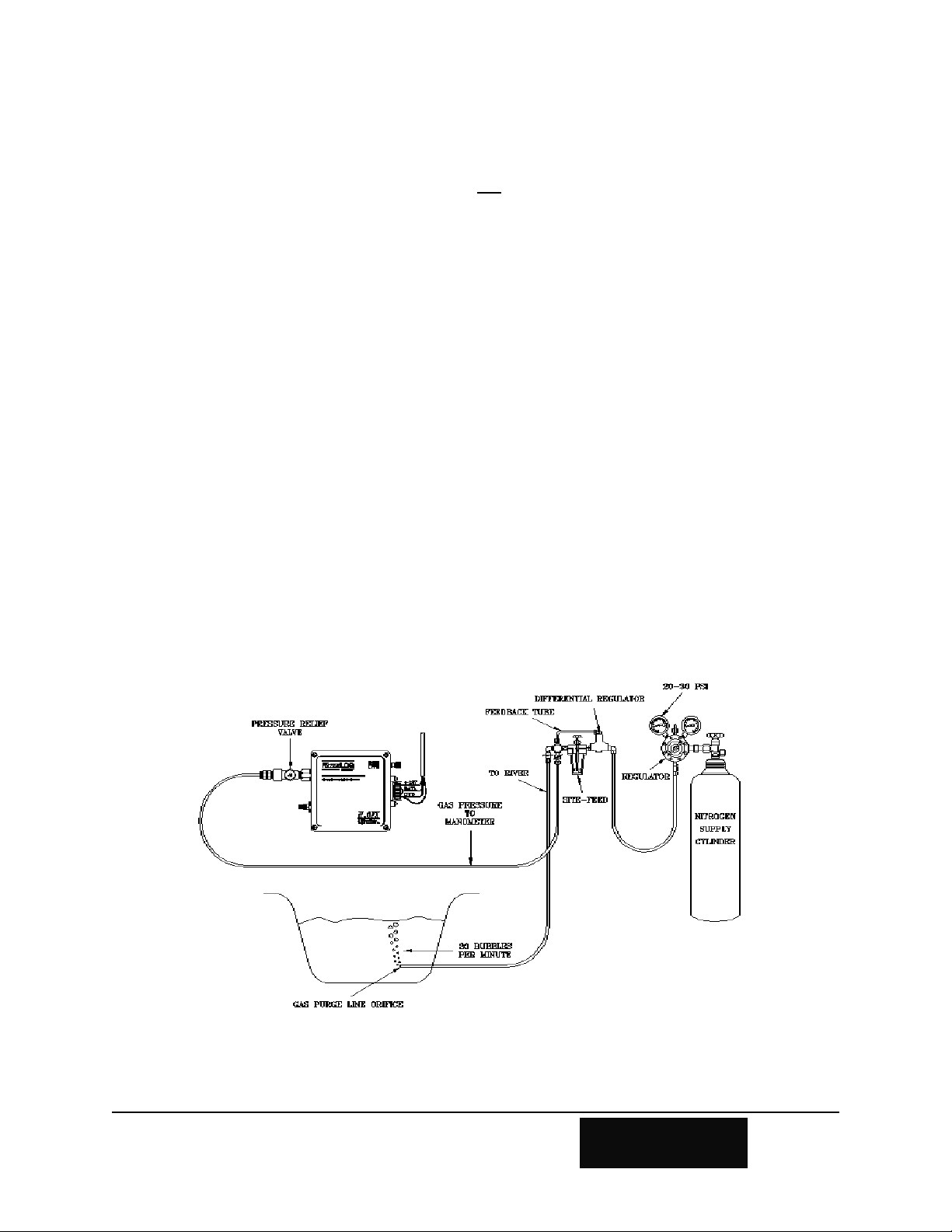
2. Connect the pressure line between the H-3531 FlashLite™ and the bubbler system.
This can be done using the H-350-Install kit, where all the required hardware is
provided. If you did not purchase the H-350-Install kit, you will need to procure the
parts from your local plumbing supplier. You will need a 1/8" NPT male tubing
fitting for the pressure input port. It is recommended that you use 1/8" copper
tubing. The proper ferrules must be used to insure there are no leaks. The male 1/8"
NPT fitting screws into the pressure input port of the H-3531 connector panel
shown in Figure 2-1. On the bubbler manifold, you will need a corresponding
tubing fitting. Generally, a 1/4" NPT female to 1/8" tubing fitting is called for. The
NPT threads of these fittings need a coat of Teflon tape or anaerobic thread dope.
This helps in preventing leaks.
We strongly recommend that you use a pressure relief valve on the pressure input. If you
purchase one, make sure that the pressure rating matches the pressure range of your H3531 FlashLite™. The pressure input requires a 1/8" NPT Male fitting. You should be
careful not to over-tighten the connector when installing it.
Figure 2-1 Gas-Purge Stream Gauge Installation
2-2 Installation H-3531
Page 15

Components of the H-350-Install kit:
• 6 feet of 1/8" copper tubing
• 1/8" Tubing to 1/8" Male NPT fitting
• 1/8" Tubing to 1/4" NPT female fitting
• 1/8" Street "T"
• 1/8" NPT Male Pressure-relief valve (Rated for the pressure range of your
H-3531 FlashLite™)
3. Connect the main interface cable to your battery and/or data logger using the
appropriate pins shown in the table on the following page. If you are using the
SDI-12 interface, also connect the SDI-12 data line to the appropriate terminal on
the data recorder(see Section 2.4.1 SDI-12 Interface).
4. Make the connection to your data recorder as explained in Section 2.4.
5. Now you are ready to field test your H-3531 FlashLite™.
H-3531 Installation 2-3
Page 16

2.4 Connecting Your Data Logger
The H-3531 FlashLite™ has SDI-12, RS232 and Modbus “smart” digital interfaces together with
quadrature, 0-5V analog and 4-20mA output. The H-3531 FlashLite™ is a SDI-12 V1.3 compliant
sensor excluding the CRC commands. It connects directly to any data recorder with SDI-12
capability. The instrument housing has a 7 pin main interface connector and a 3 pin RS232
communication connector.
7-pin Circular Connector 3-pin Circular Connector
Pin Color Function Pin Color Function
1
Orange
2
Brown
3
Blue
4
Green
5
Black
6
Red
7
Yellow
2.4.1 SDI-12 Interface
The user must connect pins 5,6, and 7 to the data recorder or the user can power the H3531 FlashLite™ separate of the data recorder and connect just the SDI-12 data line(pin
7).
2.4.2 RS-232 Output
When the user wakes up the H-3531 FlashLite™ with this port while in sleep mode the H3531 FlashLite™ makes a new measurement and updates the outputs if enabled and then
prints out the measured stage and temperature value. If the user sends a carriage
return(CR) following the wake up then the H-3531 FlashLite™ simple menu interface is
Phase A/RS485+
Phase B/RS4850-5V Out/4-20mA+
Analog Gnd/4-20mAGND
+12V Power
SDI-12 Data
1
N/A
2
N/A
3
N/A
RS232(TxD)
RS232(RxD)
GND
2-4 Installation H-3531
Page 17

initiated and the H-3531 FlashLite™ waits for a command from the menu for 3 minutes
and then times out.
2.4.3 Quadrature Output
Pins 1 and 2 of the main interface connector are for simulating a quadrature shaft encoder
output. The user can enable this option by sending the appropriate SDI-12 command or by
using the simple RS232 menu interface as explained in section 4.3.5/5.12. The quad
output uses signals Phase A and Phase B and is updated every new measurement. The user
can also put the H-3531 FlashLite™ in power mode 3, which is a continuous loop mode
that causes the H-3531 FlashLite™ to update the quadrature output at a user defined rate
which is the measure rate(see section 5.17).
2.4.4 0-5 Volt Analog Output
Pins 3 and 4 of the main interface connector are for outputting a 0-5V analog signal based
on the stage. This is also an option that the user must enable by sending the appropriate
SDI-12 command or by using the simple RS232 menu interface as explained in section
4.3.12/5.13. This output is also only updated following a new measurement. The user can
put the H-3531 FlashLite™ in power mode 3, which will update the 0-5V output based on
the measure rate.
2.5 Industrial Mode
When the user orders the H-3531 FlashLite™ the user must specify industrial mode if 4-20mA
output, Modbus/H-355 bubbler control is desired, otherwise the user must send the H-3531
FlashLite™ back to Design Analysis Associates to change to industrial mode.
2.5.1 4-20mA Output(Industrial Mode Only)
Current loop sensors output a current rather than a voltage. The 4-20mA output will drive
standard industrial telemetry and process control instrumentation. Since the signal to
noise margin of 4-20mA is not large, take care to protect the wiring from noise and
interference. The loop power supply must be sufficient to maintain 8.5 to 35V across the
H-3531 FlashLite™'s output wires, in addition to whatever voltage is needed to maintain
20mA across the loop receiver and interconnect wiring. The +12.0V SDI-12 power source
will work only if the resistance of your loop receiver and wiring is less than 150 ohms.
8.5V + (150ohms * 20mA) = 11.5V
The 4-20mA output is reverse diode protected. The H-3531 FlashLite™ is not loop
powered, continuous +12V instrument power must be supplied via the 7pin circular
connector.
!Make certain there is 8.5 to 35V across the 4-20mA output wires.
!Make certain the H-3531 FlashLite™ is receiving +12V power.
!Use shielded 4-20mA cables in noisy environments.
H-3531 Installation 2-5
Page 18

2.5.2 RS-485 Interface(Industrial Mode Only)
2.5.2.1 Modbus
Modbus is an industry standard serial digital interface for interconnecting Programmable
Logic Controllers (PLCs), intelligent sensors and other devices. The H-3531 FlashLite™
is a Modbus slave and has a serial RS-485 port for connecting to a Modbus compatible
host device. See Appendix B for the Modbus register definitions. Continuous +12Volt
power must be supplied to the H-3531 FlashLite™.
To activate the Modbus interface, the user must issue an extended SDI-12
command/change the power mode to 4 using the simple RS-232 menu interface(see
chapter 4 and 5) and set Power_Mode=4. This setting causes the H-3531 FlashLite™ to
remain awake and monitor the RS-485 port for Modbus messages. This setting can be
made at the factory if requested.
2.5.2.2 H-355 Control
The H-355 Control interface allows the user to program the H-355 Gas Purge System to
meet the environment that it is installed in. This is also an option that the user must enable
by sending the appropriate SDI-12 command or by using the simple RS232 menu interface
as explained in chapter 4 and 5. Once enabled this feature makes setting up the H-3531
FlashLite™ with the H-355 Gas Purge System quick and easy. As shown in Figure 2.1 on
page 2-2.
2-6 Installation H-3531
Page 19

2.6 Wiring and Installation Precautions
!The data recorder must be earth grounded.
!The H-3531 FlashLite™ requires that the water be at ground potential. Mother
Nature takes care of this for surface and ground water.
!Make certain the pressure port connection is tight
!Make certain the sintered bronze vent port is not painted or covered
2.7 Programming Your SDI-12 Data Recorder
You must prepare your data recorder to receive and record the H-3531 FlashLite™ data. Since
data recorders differ widely, refer to your recorder manufacturer's directions. In general, program
the data recorder to input four values via the SDI-12 port. Usually only one or two of the
parameters are actually recorded. Your data recorder must issue an “aM!” command, then collect
the data with a “aD0" command, as explained in chapter 5. The H-3531 FlashLite™ places four
parameters in its data buffer:
a+AA.AA+BB.BBBB+CC.C+DD.D<cr><lf>
Where: a = SDI-12 address 0-9, A-Z
AA.AA = Stage (feet, inches, meters etc.)
BB.BBBB = Pressure (PSI)
CC.C = Temperature (C)
DD.D = Input Supply Voltage (Volts)
2.7.1 Programming the SDI-12 Address
If more than one sensor is to be connected to the SDI-12 bus, make certain each sensor has
a different sensor address. The H-3531 FlashLite™ comes from the factory with its
address set to zero. The address can be edited using the RS-232 menu interface or using
the extended SDI-12 command. Refer to chapter 4 and 5.
2.8 Programming the H-3531 FlashLite™ Sensor
The H-3531 FlashLite™ comes from the factory with the following programmable settings:
SDI Address: 0
Slope: 2.3067 (feet of H 0)
Offset : 0.00
MeanCount: 8
Power_Mode: 0 = “Sleep”
0-5V_Hi: 34.6 (feet, 0-15psi)
0-5V_Lo: 0.0
4-20mA_Hi: 34.6 (feet, 0-15psi)
4-20mA_Lo: 0.0
2
H-3531 Installation 2-7
Page 20

With these values the Stage will be in units of feet when used in clean water. The slope can be
changed to accommodate other engineering units such as inches or meters. The setups are stored
in EEPROM within the H-3531 FlashLite™ and will not be lost if the power is disconnected. The
extended commands for changing these setups are described in detail in Chapter 5 and most of
these settings can be changed using the simple RS232 menu, see Chapter 4.
MeanCount is the number of raw pressure measurements averaged together to make one
measurement sequence. This setting determines how long the sensor will take to make a
measurement. MeanCount can be changed as described in chapter 4 and 5.
2.8.1 Setting the Stage
Many applications use the pressure sensor to measure water level in a gauge or reservoir.
The sensor translates water pressure to water level. When the H-3531 FlashLite™ is first
installed, you will want to adjust the Offset such that the measurement data (Stage)
corresponds to the current water elevation or stage as determined with a staff gauge or
other datum.
One of the ways to do this is by using the RS232 simple menu interface ran from
Hyperterminal or similar terminal program. See chapter 4 Connecting to the H-3531
FlashLite™ section. Once you have established connection your screen will look similar
2-8 Installation H-3531
Page 21

to the above screen image. When the user sets the stage the H-3531 FlashLite™ to make a
fresh measurement and automatically updates the Offset as needed to produce the desired
Stage. To set the stage using the RS-232 menu press ‘S’ for “S - Stage:” and enter in the
current stage value and then press enter. Then press the ‘M’ key for “M - Measure” and
verify that the set stage command did execute. You should see that the offset value has
changed. The other way to set the stage is to send the extended SDI-12 “Set Current
Stage” command. The “aXSCSdd.d!” command is discussed in more detail in chapter 5.
Example of a H-3531 FlashLite™ Extended "Set Current Stage" command:
Command Response Time Values Description
"aXSCS2.3!" "a0061<cr><lf>" 6sec 1 Set the Stage to 2.3
Subsequent Command Response Description
"aD0" a+12.80<cr><lf> The new Offset
2.8.2 0-5V Analog Output
The H-3531 FlashLite™ has a 12-bit digital-to-analog converter (DAC) and a precision
voltage reference. The Stage is scaled into a 12-bit value and loaded into the digital-toanalog converter. The 0-5V analog output is updated whenever a measurement is made. If
no measurements are made, the 0-5V analog output becomes “stale”. For industrial
applications where the H-3531 FlashLite™ is connected to a SCADA or PLC system
instead of a SDI-12 data logger, the H-3531 FlashLite™ can be programmed to
automatically make continuous measurements. To program the H-3531 FlashLite™ to
make continuous measurements, issue an extended SDI-12 command and set
Power_Mode=3 or use the RS-232 menu interface. See chapter 4 and 5 for details. This
setting can be made at the factory if requested.
Note: When the H-3531 FlashLite™ is first powered up and the 0-5V analog output is
enabled, the output voltage is set to 0 volts. It remains at 0 volts until the first
measurement sequence.
2.8.2.1 Programming the 0-5V Output Range
The H-3531 FlashLite™ scales the current Stage data to drive the 0-5V analog
output. The 0-5V_Hi and 0-5V_Lo settings control how the Stage data is processed.
The 0-5V_Lo should be set to the desired Stage corresponding to a 0.00 volt
output. The 0-5V_Hi should be set to the desired Stage corresponding to a 5.00 volt
output. See chapter 4 and 5 for details on programming these settings.
2.8.3 4-20mA Output(Industrial Mode Only)
The H-3531 FlashLite™ has a 12-bit digital-to-analog converter (DAC), precision voltage
reference and a 4-20mA current transmitter. The SDI-12 and 4-20mA sections are isolated
from each other with a high voltage digital opto-coupler. The Stage is scaled into a 12-bit
H-3531 Installation 2-9
Page 22

value and loaded into the digital-to-analog converter to control the current transmitter. The
4-20mA output is updated whenever a measurement is made. If no measurements are
made, the 4-20mA output becomes “stale”. For industrial applications where the H-3531
FlashLite™ is connected to a SCADA or PLC system instead of a SDI-12 data logger, the
H-3531 FlashLite™ can be programmed to automatically make continuous measurements.
To program the H-3531 FlashLite™ to make continuous measurements, issue an extended
SDI-12 command and set or use the RS-232 menu interface. See chapter 4 and 5 for
details. This setting can be made at the factory if requested.
Note: When the H-3531 FlashLite™ is first powered up, the output current is set to
4.0mA. It remains at 4.0mA until the first measurement sequence. The digital-to-analog
converter is powered from the loop side of the opto-isolator. If the loop power is
disconnected or is applied after the SDI-12 side is powered up, the data in the digital-toanalog converter will be lost. When the loop power is restored, the 4-20mA output will be
at an unknown value. Once a fresh SDI-12 measurement is made, the digital-to-analog
converter is loaded with new valid data.
2.8.3.1 Programming the 4-20mA Output Range
The H-3531 FlashLite™ scales the current Stage data to drive the 4-20mA output.
The 4-20mA_Hi and 4-20mA_Lo settings control how the Stage data is processed.
The 4-20mA_Lo should be set to the desired Stage corresponding to a 4.00mA
output. The 4-20mA_Hi should be set to the desired Stage corresponding to a
20.00mA output. See chapter 4 and 5 for more details.
2.9 Testing
Before installing the H-3531 FlashLite™ in your field location, you may wish to first test the
sensor and data logger in your shop or lab. This allows you to become familiar with H-3531
FlashLite™ and the data logger in a controlled environment. The H-3531 FlashLite™ can be
tested with a pressure standard or water filled standpipe. However, for this test to work correctly,
the standpipe must be connected to the chassis ground of the data recorder. The wire establishes
a ground connection between the water and the data logger. Water and other conductive objects
isolated by a plastic bucket or table surface pick up AC noise from nearby lighting and power
lines. The AC noise is coupled by the water to the stainless diaphragm in the pressure sensor. If
a plastic or non-conductive tube is used to connect to the pressure source to the H-3531
FlashLite™, the sensor will be electrically isolated from the water media. The AC noise may
affect the pressure measurement due to large voltages between the water media and the sensor
(data logger) ground. This precaution is not necessary for field installations because surface water
and ground water are not isolated from earth ground.
2-10 Installation H-3531
Page 23

Chapter 3
Maintenance/Troubleshooting
3.1 Maintenance
Sustained operation of the H-3531 FlashLite™ pressure sensor is almost maintenance free. As
with any precision instrument, the calibration should be checked on a regular basis. The
instrument has no filters or user serviceable internal parts.
3.2 Precautions
!Check for leaks, make certain the connections to the pressure port are tight.
!Make certain the atmospheric vent is not covered or blocked.
!Make certain the gauge station enclosure is open to the atmosphere. If the sensor is placed
in a cabinet or sealed enclosure, the cabinet must have a screened vent or other opening to
the atmosphere.
3.3 Troubleshooting
Experience over the years with pressure sensors has identified several common problems:
No SDI-12 response or intermittent data
1. Check all wiring including power and ground connections. Battery connections can
become corroded. Check for corrosion in the connectors and terminal strips.
2. The H-3531 FlashLite™ measures and reports it’s internal power supply voltage
along with Stage, Pressure and Temperature. Make a measurement and check to
see if the voltage is between 10.0 and 16.0 Volts.
3. Check the connections between your data recorder and the H-3531 FlashLite™
sensor. The power connections are made on the 7-pin circular connector.
4. Verify that there is not another SDI-12 sensor on the SDI-12 bus with the same
SDI-12 address as the H-3531 FlashLite™. Try communicating with the H-3531
FlashLite™ without any other SDI-12 devices on the bus. Sending a “*!” or “?!”
should cause the H-3531 FlashLite™ to return its own address as long as there are
no other SDI-12 devices on the SDI-12 bus.
Please feel free to call the factory for technical assistance and also with solutions you have found
to past problems.
H-3531 Maintenance 3-1
Page 24

2-2 Installation H-3531
Page 25

Chapter 4
Simple Menu Interface
4.0 Simple Menu Interface
The H-3531 FlashLite™ has a RS-232 interface which is convenient for setup and testing. This
chapter is a description of the Simple Menu interface. Included is a description of the menu and
each setup option.
4.1 Connecting to the H-3531 FlashLite™
The Simple Menu interface is designed to work with a terminal program such as Hyper-Terminal,
Procom or other similar terminal programs. The following table shows the settings that are needed
for communication with the H-3531 FlashLite™.
COMMUNICATION
SETTING
BAUD RATE:
DATA BITS:
STOP BITS:
PARITY:
DUPLEX:
TERMINAL EMULATION:
FLOW CONTROL:
After the computer is connected, pressing any key ONCE! (while the H-3531 FlashLite™ is in
sleep mode) will cause the H-3531 FlashLite™ to wake up, make a new measurement and print
the following message:
Stage = +/-X.XX
Temp = +/-XX.X
When the ENTER key is pressed after the H-3531 FlashLite™ is awake it will invoke the H-3531
FlashLite™ Simple Menu. You will see a “Measuring...” message displayed as the H-3531
FlashLite™ makes a fresh measurement. Then the H-3531 FlashLite™ will display the Simple
Menu as shown on the following page.
H-3531 FlashLite™
SETTINGS
9600
8
1
None
Full
VT-100
Software (Xon / Xoff)
Note: When the P key is pressed after the H-3531 FlashLite™ is awake it will invoke a purge if
the H-355 bubbler is enabled and present.
H-3531 Simple RS-232 Menu Interface 4-1
Page 26

4.2 General Operations
The H-3531 FlashLite™ settings can be made either via the Simple Menu or with extend SDI-12
commands. This chapter focuses on the Simple Menu interface.
The menu displays a list of available options. The right column is status information and cannot
be edited. At the bottom of the screen is an “Enter Option >” prompt. Enter the desired menu
option here, the ENTER key does not have to be pressed.
Some options, when selected act as a toggle and will change when selected. These options only
have two choices such as: On/Off. Options with brackets “[ ]” allow the user to set or
change a value. After entering the requested value within the brackets, press ENTER to make the
change. If you do not want to edit the option that has been selected, press the ESC key and the edit
will be aborted.
H-3531 FlashLite Interface Menu
P - Sensor Mode Options Serial#: 001000
V - Sensor Output Options Version: 1.90
B - H-355 Bubbler Options Temp: +72.2
A - SDI-12 Address: 0 Battery: +13.8
S - Stage: +46.13
D - Digits: +2
O - Offset: +0.0000
U - Units: Feet
L - Slope: +2.30670
C - Averaged Measurements: +8 (+6 sec)
M - Measure
H - H-355 Bubbler: Off
X - Exit
Enter Option >
4.3 Menu Options
4.3.1 P - Sensor Mode Options
In this sub-menu you can view the current H-3531 FlashLite™ power mode settings or
other modes if available and change the modes if desired. Refer to section 4.4 for the
Sensor Mode Options sub-menu options.
4.3.2 V - Sensor Output Options
In this sub-menu you can view the current H-3531 FlashLite™ output options and enables.
In this sub-menu you can change these options and enables. Refer to section 4.5 for the
Sensor Output Options menu options.
4-2 Simple RS-232 Menu Interface H-3531
Page 27

4.3.3 B - H-355 Bubbler Options
In this sub-menu you can view and edit H-355 bubbler settings if the option is enabled and
the bubbler is present. If the bubbler option is not enabled you will see the following
message after pressing the B key.
Enter Option >H-355 Bubbler not enabled.
Press Any Key...
When the bubbler is enabled the screen will refresh and the following message will be
displayed.
Gathering H-355 Bubbler Data...
This message means the H-3531 FlashLite™ is attempting to establish communication
with the H-355 Gas Purge System and then it will gather all the available H-355 bubbler
data. If the communication and data retrieval was not successful then the main menu will
be displayed. If the communication was successful then the user will see the H-355
Bubbler Setup Menu. Refer to section 4.6 for details.
4.3.4 A - SDI-12 Address
This option is for editing the SDI-12 sensor address of the H-3531 FlashLite™. The
following prompt appears the bottom of the menu.
Enter Option >Enter New SDI-12 Address [ ]
Enter the desired SDI-12 sensor address (0-9, a-z, A-Z), the menu will refresh with the
new address.
4.3.5 S - Stage
This option is for displaying the last measured stage value and also for setting the current
stage. The following prompt at the bottom of the menu.
Enter Option >Enter Stage Value[ ]
Enter the stage setting you desire and press the ENTER key. The message
“Calculating New Offset...” will then be displayed. The H-3531 FlashLite™
makes a new measurement and then calculates the offset needed to obtain the desired stage
setting. When the measurement is complete the offset value will have changed. You must
make a new measurement “M” to see the results of the new offset.
4.3.6 D - Digits
This option is for displaying the current stage digits to the right of the decimal and also for
editing the number of digits to the right of the decimal. After pressing the D key the user
will see the following prompt at the bottom of the menu.
Enter Option >Stage Digits [ ]
H-3531 Simple RS-232 Menu Interface 4-3
Page 28

Then the user can enter in the desired digits to the right of the decimal and press the
ENTER key to input the value. The screen will then refresh with the digits value changed.
4.3.7 O - Offset
This option is for displaying the current stage offset value and also for editing the stage
offset value manually. The following prompt appears at the bottom of the menu.
Enter Option >Enter Offset Value[ ]
Enter the desired stage offset value and press the ENTER key to input the value. The
screen will refresh and show the new offset. You must make a new measurement “M” to
see the results of the new offset.
4.3.8 U - Units
This option is for displaying the current stage units and also for editing the stage units.
The following prompt appears at the bottom of the menu.
Enter Option >Stage Units [Feet ]
Using the up and down arrows select the desired units for stage. The available stage units
are feet, meters, inches, millimeters, centimeters, psi, and user defined. After selecting the
desired units the slope will get set to the required slope to accomplish the desired units.
4.3.9 L - Slope
This option is for displaying the current stage slope and also for editing the stage slope.
The following prompt appears at the bottom of the menu.
Enter Option >Enter Slope Value[ ]
Enter the new stage slope and press the Enter key to input the value. The screen will
refresh and show the new slope. You must make a new measurement “M” to see the
results of the new stage slope.
4.3.10 C - Averaged Measurements
This option is for displaying the current Averaged Measurements/Meancount value and for
editing the value. The option also displays the estimated time that the measurement will
take due to the amount of averaging. The following prompt at the bottom of the menu.
Enter Option >Averaged Measurements [ ]
Enter the new averaged measurements/meancount and press the ENTER key. Refer to
Chapter-5 for more details on the meancount value.
4.3.11 M - Measure
Pressing the M key causes the H-3531 FlashLite™ to make a new measurement and
refresh the screen with the new measurement data. The user will see the following
4-4 Simple RS-232 Menu Interface H-3531
Page 29

message after pressing the M key.
Enter Option >Measuring...
4.3.12 H - H-355 Bubbler
This is the enable for the H-355 bubbler option. Once enabled the user can use H-3531
FlashLite™ to edit the settings in a H-355 Gas Purge System. After pressing the B key the
screen will refresh with the option changed.
4.3.13 X - Exit
Pressing the X key causes the H-3531 FlashLite™ to exit the Simple Menu mode. The
user will see the following message after pressing the X key.
Enter Option >
H-3531 FlashLite Off
H-3531 Simple RS-232 Menu Interface 4-5
Page 30

4.4 Sensor Mode Options Menu
This setup menu is for viewing and editing the H-3531 FlashLite™ power modes and other mode
enables.
Sensor Mode Options Menu
P - Power Mode: 0
F - Fast Mode: Off
N - NOAA Mode: Off
D - Reset to Defaults
Enter Option >
4.4.1 P - Power Mode
This option is for changing the H-3531 FlashLite™. The following prompt at the bottom
of the menu.
Enter Option >Power Mode Value(0-4) [ ]
Enter in the desired power mode.
Power Modes:
0 = Sleep between measurements
1 = Sleep with sensor bias On (reserved for factory use)
2 = Sleep with sensor bias and reference On (reserved for factory use)
3 = Wait mode. Make measurements and update all outputs based on the measure rate
4 = Wait mode. Power profile for Modbus
The menu will refresh with the new power mode.
4.4.2 F - Fast Mode
This option is the enable for putting the H-3531 FlashLite™ in a special mode called Fast
Mode. Fast Mode causes the H-3531 FlashLite™ to complete measurements in 1 second
vs. the normal mode which takes about 6 seconds. This mode is not recommended
because the atmospheric pressure and temperature values are only updated every 3 minutes
and the H-3531 FlashLite™ does not average as many measurements. When in this mode
the Meancount/Averaged measurements value are not used. But if there is an application
where the user needs the H-3531 FlashLite™ to measure that fast this mode does work.
Therefore, the user may lose some accuracy using this mode because the H-3531
FlashLite™ is calibrated in the normal mode with the atmospheric pressure and
temperature measured every measurement. After pressing the F key the screen will
refresh with the option changed.
4.4.3 N - NOAA Mode
This options is the enable for putting the H-3531 FlashLite™ in NOAA Mode. NOAA
4-6 Simple RS-232 Menu Interface H-3531
Page 31

Mode causes the H-3531 FlashLite™ to complete measurements in less than 1 second.
This mode is for NOAA applications where the data collection platform requests a
measurement/second for 3minutes and then requests no measurements for 3 minutes.
When in this mode the Meancount/Averaged measurements variable is not used. But this
is a requirement for NOAA application. After pressing the N key the screen will refresh
with the option changed.
4.4.4 R - Measure Rate (Power Mode 3)
This option is a hidden menu option that is only available when the H-3531 FlashLite™ is
on power mode 3. This option is viewing and editing the current measure rate value.
After pressing the R key the user will see the following prompt at the bottom of the menu.
Enter Option >Measure Rate(0-255)[ ]min
Then the user can enter in the desired measure rate. After entering the desired measure
rate press the ENTER key to submit the value and then the screen will refresh with the
option changed if the value was valid. If the user does not want to change the measure rate
then press the ESC key to abort.
4.4.5 M - Modbus Settings (Power Mode 4)
This option is a hidden menu option that is only available when the H-3531 FlashLite™ is
on power mode 4 (modbus mode). Pressing the M key will take the user to the “Modbus
Settings” menu. The is shown below.
4.4.5.1
Modbus Settings Menu
This menu is for viewing and editing the current Modbus settings.
4.4.5.2 A - Address
This option is for displaying or changing the current modbus address. The valid
range for the modbus address is 1 - 247. Pressing the A key will show the
following prompt at the bottom of the screen.
Enter Option >Modbus Address(1-247)[ ]
Enter the desired modbus address, the menu will refresh with the new address.
Modbus Settings Menu
A - Address: 1
B - Baud Rate: 9600
P - Parity: Even
Enter Option >
H-3531 Simple RS-232 Menu Interface 4-7
Page 32

4.4.5.3 B - Baud Rate
This option is for displaying or changing the current baud rate for the RS-485
Modbus communications port. Pressing the B key will show the following
message at the bottom of the screen.
Enter Option >Modbus Baud Rate [9600]
Press the up or down key to change the baud rate selections and then press the
ENTER key to accept the selection.
4.4.5.3 P - Parity
This option is for displaying or changing the current parity for the RS-485 Modbus
communications port. Pressing the P key will show the following message at the
bottom of the screen.
Enter Option >Modbus Parity [Even]
Press the up or down key to change the parity and then press the ENTER key to
accept the selection.
4.4.6 D - Reset to Defaults
This option will reset the H-3531 FlashLite™ back to factory user defaults. The following
message will be displayed.
Enter Option >Resetting to Defaults...
4.5 Sensor Output Setup Menu
Sensor Output Setup Menu
0-5v Output Options:
Slope = +.144506
V - 0-5v Output: Off
H - Max Stage: +34.60
L - Min Stage: +0.00
4-20mA Output Options:
Slope = +.462427
M - Max Stage: +34.60
N - Min Stage: +0.00
Quad Output Options:
Q - Quad Output: Off
U - Update Outputs
Enter Option >
This setup menu is for
viewing or editing the current
settings for the 0-5v analog
output and 4-20mA output.
4-8 Simple RS-232 Menu Interface H-3531
Page 33

4.5.1 0-5v Output Options
4.5.1.1 Slope
This is the current slope that the H-3531 FlashLite™ has calculated based on the
max and min stage values.
4.5.1.2 V - 0-5v Output
This option is the enable for the 0-5v analog output. Once the 0-5v output is
enabled the H-3531 FlashLite™ will update the 0-5v output based on stage
following a new measurement. After pressing the V key the screen will refresh
with the option changed.
4.5.1.3 H - Max Stage
This option is the max stage value that the 0-5v output will be scaled up to. After
pressing the H key the user will see the following message.
Then the user can enter in the 0-5v max stage value and press the ENTER key to
submit the value. If the user does not want to edit the 0-5v max stage value then
press the ESC key to abort. Refer to section 5.14 in SDI-12 commands for more
details about editing this value.
Enter 0-5v Max Stage[ ]
4.5.1.4 L - Min Stage
This option is the min stage value that the 0-5v output will be scaled down to.
After pressing the L key the user will see the following message.
Enter 0-5v Min Stage[ ]
Then the user can enter in the 0-5v min stage value and press the ENTER key to
submit the value. If the user does not want to edit the 0-5v min stage value then
press the ESC key to abort. Refer to section 5.14 in SDI-12 commands for more
details about editing this value.
4.5.2 4-20mA Output Options
4.5.2.1 Slope
This is the current slope that the H-3531 FlashLite™ has calculated based on the
max and min stage values.
4.5.2.2 M - Max Stage
H-3531 Simple RS-232 Menu Interface 4-9
Page 34

This option is the max stage value that the 4-20mA output will be scaled up to.
After pressing the M key the user will see the following message.
Enter 4-20mA Max Stage[ ]
Then the user can enter in the 4-20mA max stage value and press the ENTER key
to submit the value. If the user does not want to edit the 4-20mA max stage value
then press the ESC key to abort. Refer to section 5.15 in the SDI-12 command and
Response protocol chapter for more details about editing this value.
4.5.2.3 N - Min Stage
This option is the min stage value that the 4-20mA output will be scaled down to.
After pressing the N key the user will see the following message.
Enter 4-20mA Min Stage[ ]
Then the user can enter in the 4-20mA min stage value and press the ENTER key
to submit the value. If the user does not want to edit the 4-20mA min stage value
then press the ESC key to abort. Refer to section 5.15 in SDI-12 command and
Response protocol chapter for more details about editing this value.
4.5.3 Q - Quad Output
This option is the enable for the Quadrature Shaft Encoder output. Once enabled the H3531 FlashLite™ will output quad counts based on a change in stage following a
measurement. After pressing the Q key the screen will refresh with the option changed.
4.5.4 U - Update Outputs
This option is for forcing the H-3531 FlashLite™ to make a new measurement which
causes the enabled outputs to be updated. After pressing the U key the user will the
following message.
Enter Option >Measuring...
4.6 H-355 Bubbler Setup Menu
The H-355 Bubbler Setup Menu is for viewing or editing the current settings in H-355 Gas Purge
System. The following screen is what the user will see upon successful communication with the
H-355. In this section we will discuss the different options found on this menu.
4-10 Simple RS-232 Menu Interface H-3531
Page 35

H-355 Bubbler Setup Menu
Tank Pressure: +2.44
Line Pressure: -.09
B - Bubble Rate: +60
P - Purge Pressure: +40
D - Purge Duration: +50
A - Auto Purge: Off
T - Purge Threshold: +20
M - Manual Purge
U - Update All Values
Enter Option >
4.6.1 Tank Pressure
This is a bubbler status value and cannot be edited by the user. This is the tank pressure
value that was measured by the H-355.
4.6.2 Line Pressure
This is a bubbler status value and cannot be edited by the user. This is the line pressure
that was measured by the H-355.
4.6.3 B - Bubble Rate
This option is for displaying the current bubble rate and also for editing the bubble rate.
After pressing the B key the user will see the following prompt at the bottom of the menu.
Enter Bubble Rate(30-120)[ ]
Then the user can enter in the new bubble rate and press the Enter key to input the value.
After the bubble rate is entered the screen will refresh with the bubble rate changed. If the
user does not want to edit the bubble rate then press the ESC key to abort. The user can
change the bubble rate from 30 to 120 bubbles/minute.
4.6.4 P - Purge Pressure
This option is for displaying the current purge pressure and also for editing the purge
pressure. After pressing the P key the user will see the following prompt at the bottom of
the menu.
Enter Purge Pressure(15-80)[ ]
Then the user can enter in the new purge pressure and press the Enter key to input the
value. After the purge pressure is entered the screen will refresh with the purge pressure
changed. If the user does not want to edit the purge pressure then press the ESC key to
abort. The user can change the purge pressure from 15 to 80 psi.
4.6.5 D - Purge Duration
This option is for displaying the current purge duration and also for editing the purge
H-3531 Simple RS-232 Menu Interface 4-11
Page 36

duration. After pressing the D key the user will see the following prompt at the bottom of
the menu.
Enter Purge Duration(10-240)[ ]
Then the user can enter in the new purge duration and press the Enter key to input the
value. After the purge duration is entered the screen will refresh with the purge duration
changed. If the user does not want to edit the purge pressure then press the ESC key to
abort. The user can change the purge duration from 10 to 240 seconds.
4.6.6 A - Auto Purge
This option is for enabling/disabling auto purge. When enabled the H-355 Gas Purge
System will purge automatically when the line pressure meets or exceeds the purge
pressure value. After pressing the A key the screen will refresh with the option changed.
4.5.7 T - Purge Threshold
This option is for displaying the current purge threshold for the auto purge and also for
editing the purge threshold. After pressing the T key the user will see the following
prompt at the bottom of the menu.
Enter Purge Threshold(10-65)[ ]
Then the user can enter in the new purge threshold and press the Enter key to input the
value. After the purge threshold is entered the screen will refresh with the purge threshold
changed. If the user does not want to edit the purge threshold then press the ESC key to
abort. The user can change the purge threshold from 10 to 65 psi.
4.6.8 M - Manual Purge
This option is for requesting the H-355 Gas Purge System to purge. After pressing the M
key the user will see the following message at the bottom of the menu.
Initiating Purge...
The screen will refresh once the request has been made successfully and the H-355 Gas
Purge System will purge shortly following the refresh.
4.6.9 U - Update All Values
This option is for requesting all new updated values from the H-355 Gas Purge System.
After pressing the U key the screen will be cleared and the user will see the following
message at the top of the screen.
Gathering H-355 Bubbler Data...
The screen will refresh with the new values once the request has been made successfully.
4-12 Simple RS-232 Menu Interface H-3531
Page 37

Note: If there is a communication error while reading or editing the H-355 Gas Purge
System values the user will see the following message.
Communication Error...
Press Any Key...
This message will stay for about 5 seconds and then the H-3531 FlashLite™ will try to
establish communication again and if this is unsuccessful the H-3531 FlashLite™ will
return to the main menu. If this happens check the cables for the H-355 Gas Purge System
for loose connections.
Page 38

4-14 Simple RS-232 Menu Interface H-3531
Page 39

Chapter 5
SDI-12 Command and Response Protocol
5.0 SDI-12 Command and Response Protocol
This is a brief description of the Serial Digital Interface (SDI-12) Command and Response
Protocol used by the WATERLOG Series Model H-3531 FlashLite™ sensor. Included is a
description of the commands and data format supported by the H-3531 FlashLite™.
Refer to the document "A SERIAL DIGITAL INTERFACE STANDARD FOR
MICROPROCESSOR-BASED SENSORS.” Version 1.3 July 25, 2004 Prepared by the SDI-12
Support Group, 165 East 500 South River Heights, Utah.(http://www.sdi-12.org)
Note: The H-3531 FlashLite™ incorporates V1.3 with the exception of the CRC request.
During normal communication, the data recorder sends an address together with a command to
the H-3531 FlashLite™ SDI-12 sensor. The H-3531 FlashLite™ then replies with a "response."
In the following descriptions, SDI-12 commands and responses are enclosed in quotes. The
SDI-12 address and the command/response terminators are defined as follows:
"a" Is the sensor address. The following ASCII Characters are valid addresses:
"0-9", "A-Z", "a-z", "*", "?". Sensors will be initially programmed at the
factory with the address of "0" for use in single sensor systems. Addresses
"1 to 9" and "A to Z" or "a to z" can be used for additional sensors
connected to the same SDI-12 bus. Address "*" and "?" are "wild card"
addresses which select any sensor, regardless of its actual address.
®
Notes:
"!" Is the last character of a command block.
"<cr><lf>" Are carriage return (0D) hex and line feed (0A) hex characters. They are
the last two characters of a response block.
• All commands/responses are upper-case printable ASCII characters.
• Commands must be terminated with a "!" character.
• Responses are terminated with <cr><lf> characters.
• The command string must be transmitted in a contiguous block with no gaps of
more than 1.66 milliseconds between characters.
H-3531 SDI-12 Command and Response Protocol 5-1
Page 40

5.1 Measure Command
The Measure Command causes a new measurement sequence to be executed. Data values
generated in response to this command are stored in the sensor's buffer for subsequent collection
using "D" commands. The data will be retained in the sensor until another "M", " C", or "V"
command is executed.
Command Response Description
"aM!" "atttn<cr><lf>" Initiate measurement
"aM1!" "atttn<cr><lf>" Initiate measurement
Where:
a is the sensor address ("0-9", "A-Z", "a-z", "*", "?").
M is an upper-case ASCII character
ttt is a three digit integer (000-999) specifying the maximum time, in seconds,
the sensor will take to complete the command and have measurement data
available in its buffer.
n is a single digit integer (0-9) specifying the number of values that will be
placed in the data buffer. If "n" is zero (0), no data will be available using
subsequent "D" commands.
Upon completion of the measurement, a service request "a<cr><lf>" is sent to the data recorder
indicating the sensor data is ready. The data recorder may wake the sensor with a break and
collect the data any time after the service request is received or the specified processing time has
elapsed.
Example of a H-3531 "aM!" command:
Command Response Time Values Description
"aM!" "a0064<cr><lf>" 6 sec 4 Make measurement
Subsequent Command Response
"aD0" a+AA.AA+BB.BBBB+CC.C+DD.D<cr><lf>
Where:
AA.AA = Stage (feet, inches, meters etc.)
BB.BBBB = Pressure (PSI)
CC.C = Temperature (C)
DD.D = Power Supply Voltage (Volts)
5-2 SDI-12 Command and Response Protocol H-3531
Page 41

Example of a H-3531 "aM1!" command:
Command Response Time Values Description
"aM1!" "a0064<cr><lf>" 6 sec 4 Make measurement
Subsequent Command Response
"aD0" a+AA.AAAA+BB.B+CCCCCCC.CC+DDDDDDD.DD<cr><lf>
Where:
AA.AAAA = Pressure (PSI)
BB.B = Temperature (C)
CCCCCCC.CC = Raw Pressure A/D Counts
DDDDDDD.DD = Raw Temperature A/D Counts
H-3531 SDI-12 Command and Response Protocol 5-3
Page 42

5.2 Measure H-355 Gas Purge System
This Measure Command causes a new measurement sequence to be executed in the H-355 Gas
purge system. The Data values generated are the Tank and Line PSI as well as the difference.
Data values in response to this command are stored in the sensor's buffer for subsequent collection
using "D" commands. The data will be retained in the sensor until another "M", " C", or "V"
command is executed.
Command Response Description
"aM2!" "atttn<cr><lf>" Measure H-355 Tank and Line PSI
Where:
a is the sensor address ("0-9", "A-Z", "a-z", "*", "?").
M is an upper-case ASCII character
ttt is a three digit integer (000-999) specifying the maximum time, in seconds,
the sensor will take to complete the command and have measurement data
available in its buffer.
n is a single digit integer (0-9) specifying the number of values that will be
placed in the data buffer. If "n" is zero (0), no data will be available using
subsequent "D" commands.
Upon completion of the measurement, a service request "a<cr><lf>" is sent to the data recorder
indicating the sensor data is ready. The data recorder may wake the sensor with a break and
collect the data any time after the service request is received or the specified processing time has
elapsed.
Example of a H-3531 "aM2!" command:
Command Response Time Values Description
"aM2!" "a0053<cr><lf>" 5 sec 3 Make measurement
Subsequent Command Response
"aD0" a+AA.A+BB.B+CC.C<cr><lf>
Where:
AA.A = Tank Pressure (PSI)
BB.B = Line Pressure (PSI)
CC.C = Difference between Tank and Line (PSI)
5-4 SDI-12 Command and Response Protocol H-3531
Page 43

5.3 Concurrent Measurement Command
This is a new command since the release of Version 1.2 SDI-12 Specification. A concurrent
measurement is one which occurs while other SDI-12 sensors on the bus are also taking
measurements. This command is similar to the “aM!” command, however, the nn field has an
extra digit and the sensor does not issue a service request when it has completed the measurement.
Communicating with other sensors will NOT abort a concurrent measurement. Data values
generated in response to this command are stored in the sensor's buffer for subsequent collection
using "D" commands. The data will be retained in the sensor until another "M", "C", or "V"
command is executed.
Command Response Description
"aC!" "atttnn<cr><lf>" Initiate measurement
Where:
a is the sensor address ("0-9", "A-Z", "a-z", "*", "?").
C is an upper-case ASCII character
ttt is a three digit integer (000-999) specifying the maximum time, in seconds, the
sensor will take to complete the command and have measurement data available in
its buffer.
nn is a two digit integer (00-99) specifying the number of values that will be
placed in the data buffer. If "n" is zero (0), no data will be available using
subsequent "D" commands.
The data recorder may wake the sensor with a break and collect the data anytime after the
specified processing time has elapsed.
Example of a H-3531 "aC!" command:
Command Response Time Values Description
"aC!" "a00604<cr><lf>"6 sec 04 Make measurement
Subsequent Command Response
"aD0" a+AA.AA+BB.BBBB+CC.C+DD.D<cr><lf>
Where:
AA.AA = Stage (feet, inches, meters etc.)
BB.BBBB = Pressure (PSI)
CC.C = Temperature (C)
DD.D = Power Supply Voltage (Volts)
H-3531 SDI-12 Command and Response Protocol 5-5
Page 44

5.4 Send Data Command
The Send Data command returns sensor data generated as the result of previous "aM!", "aC!", or
"aV!" commands. Values returned will be sent in 33 characters or less. The sensor's data buffer
will not be altered by this command.
Command Response
"aD0!" through "aD9!" "apd.d ... pd.d<cr><lf>"
Where:
a is the sensor address ("0-9", "A-Z", "a-z", "*", "?").
D0..D9 are upper-case ASCII characters.
p Is a polarity sign (+ or -)
d.d represents numeric digits before and/or after the decimal. A decimal may
be used in any position in the value after the polarity sign. If a decimal is
not used, it will be assumed to be after the last digit.
For example: +3.29 +23.5 -25.45 +300
If one or more values were specified and a "aD0!" returns no data (<CR><LF> only), it means
that the measurement was aborted and a new "M" command must be sent.
Example of a H-3531 "aD0!" command:
Previous Command Response
"aM!" "a0064<cr><lf>"
Subsequent Command Response
"aD0" a+AA.AA+BB.BBBB+CC.C+DD.D<cr><lf>
Where:
AA.AA = Stage (feet, inches, meters etc.)
BB.BBBB = Pressure (PSI)
CC.C = Temperature (C)
DD.D = Power Supply Voltage (Volts)
5-6 SDI-12 Command and Response Protocol H-3531
Page 45

5.5 Continuous Measurements
This is a new command for the Version 1.2 SDI-12 Specification. Sensors that are able to
continuously monitor the phenomena to be measured, such as a cable position, do not require a
start measurement command. They can be read directly with the R commands (R0!...R9!). The R
commands work exactly like the D (D0!...D9!) commands. The only difference is that the R
commands do not need to be preceded with an M command.
The H-3531 FlashLite™ does not support the aR0! continuous measurement commands because
the measurement and math operations require several seconds to complete..
5.6 Send Acknowledge Command
The Send Acknowledge Command returns a simple status response which includes the address of
the sensor. Any measurement data in the sensor's buffer is not disturbed.
Command Response
"a!" "a<cr><lf>"
Where: a Is the sensor address ("0-9", "A-Z", "a-z", "*", "?").
Example of H-3531 "a!" command:
Command Response Time Values Description
"a!" "a<cr><lf>" 0 sec 0 Return the address of sensor
H-3531 SDI-12 Command and Response Protocol 5-7
Page 46

5.7 Initiate Verify Command
The Verify Command causes a verify sequence to be performed. The result of this command is
similar to the "aM!" command except that the values generated are fixed test data and the results
of diagnostic checksum tests. The data generated in response to this command is placed in the
sensor's buffer for subsequent collection using "D" commands. The data will be retained in the
sensor until another "M", "C", or "V" command is executed.
Command Response Description
"aV!" "atttn<cr><lf>" Initiate verify sequence
Where:
a is the sensor address ("0-9", "A-Z", "a-z", "*", "?").
V is an upper-case ASCII character.
ttt is a three digit integer (000-999) specifying the maximum time, in seconds, the
sensor will take to complete the command and have data available in its buffer.
n is a single digit integer (0-9) specifying the number of values that will be
placed in the data buffer. If "n" is zero (0), no data will be available using
subsequent "D" commands
Example of a "aV!" command:
Command Response Time Values Description
"aV!" "a0014<cr><lf>" 1 sec 4 Return fixed data and diagnostic data
for testing purposes.
Subsequent Command Response
"aD0" a+123.456+78.9+ddddd+y<cr><lf>
Key Description Units
+123.456 Fixed test data
+78.9 Fixed test data
+ddddd ROM checksum value (0-99999)
+y ROM checksum test 0 = Failed, 1 = Passed
5-8 SDI-12 Command and Response Protocol H-3531
Page 47

5.8 Send Identification Command
The Send Identification Command responds with sensor vendor, model, and version data. Any
measurement data in the sensor's buffer is not disturbed.
Command Response
"aI!" "allccccccccmmmmmmvvvxx...xx<cr><lf>"
Where:
a is the sensor address ("0-9", "A-Z", "a-z", "*", "?").
I is an upper-case ASCII character.
ll is the SDI-12 version compatibility level, e.g. version 1.2 is represented as
"12".
cccccccc is an 8 character vendor identification to be specified by the vendor and
usually in the form of a company name or its abbreviation.
mmmmmm is a 6 character field specifying the sensor model number.
vvv is a 3 character field specifying the sensor version number.
xx...xx is an optional field of up to a maximum of 13 characters to be used for
serial number or other specific sensor information not relevant to operation
of the data recorder.
Example of a "aI!" command:
"a13 DAA H3531vvvS#nnnnnnVkkk<cr><lf>"
H-3531 FlashLite™ implementation of the optional 13 character field:
S#nnnnnnVkkk (12 bytes total)
Where:
"nnnnnn" is a six character sensor serial number
"kkk" is a three digit sensor firmware revision level
H-3531 SDI-12 Command and Response Protocol 5-9
Page 48

5.9 Change Sensor Address Command
The Change Sensor Address Command allows the sensor address to be changed. The address is
stored in non-volatile EEPROM within the sensor. The H-3531 FlashLite™ will not respond if
the command was invalid, the address was out of range, or the EEPROM programming operation
failed.
Command Response Description
"aAn!" "n<cr><lf>" Change sensor address
Where:
a is the current (old) sensor address ("0-9", "A-Z", "a-z", "*", "?"). An ASCII
"*" may be used as a "wild card" address if the current address is unknown
and only one sensor is connected to the bus.
A is an upper-case ASCII character.
n is the new sensor address to be programmed ("0-9", "A-Z").
NOTE: To verify the new address use the "Identify Command."
Example of a "Change Sensor Address" command:
Command Response Description
"aA2!" "2<cr><lf>" Change sensor address to "2"
5-10 SDI-12 Command and Response Protocol H-3531
Page 49

5.10 Extended Set Current Stage Command
The H-3531 FlashLite™ processes the pressure sensor input and computes Pressure in PSI units.
Stage is computed with a Stage = m * Pressure + b equation. During installation it is convenient
to quickly set the H-3531 FlashLite™'s Stage reading to match the current stage, elevation or
pressure of the water as determined by a staff gauge or other datum. This command causes the H3531 FlashLite™ to make a fresh measurement and automatically update the Offset (b) term as
needed to produce the desired Stage.
Command Response Description
"aXSCSddd!" “a0061<cr><lf>" Set current Stage
Where: a is the sensor address ("0-9", "A-Z", "a-z", "*", "?").
XSCS are upper case characters.
ddd is the new current stage value.
Example of a H-3531 Extended "Set Current Stage" command:
Command Response Time Values Description
"aXSCS2.3!" "a0061<cr><lf>" 6 sec 1 Set the Stage to 2.3
Subsequent Command Response Description
"aD0" a+1.80<cr><lf> The new Offset
H-3531 SDI-12 Command and Response Protocol 5-11
Page 50

5.11 Extended Read/Write Offset and Read/Write Slope
The H-3531 FlashLite™ processes the pressure sensor input and computes Pressure in PSI units.
Stage is computed with a Stage = m * Pressure + b equation. The Slope (m) and Offset (b) terms
are programmable, allowing the user to scale the reading into other engineering units. These
commands allow the user to read or write (change) the Slope and Offset terms. The slope is set to
2.3067 and the offset to 0.00 at the factory. With the factory default (2.3067) the Stage will be in
units of water depth (in feet). The new values are stored in non-volatile EEPROM within the
sensor. Once the new Slope or Offset value is written to the EEPROM, a copy is sent to the sensor
data buffer for verification. This data can be viewed by using a subsequent "D" command. To
verify these settings any other time, use the "XRS" or “XRO” commands. This command takes
001 seconds to complete and places 1 value in the data buffer. Use the “aD0" command to collect
and view the new slope or offset.
Command Response Description
"aXRS!" “a0011<cr><lf>" Read Slope
"aXRO!" “a0011<cr><lf>" Read Offset
"aXWSddd!" “a0061<cr><lf>" Write Slope
"aXWOddd!" “a0061<cr><lf>" Write Offset
Where: a is the sensor address ("0-9", "A-Z", "a-z", "*", "?").
XRS are upper case characters.
XRO are upper case characters.
XWS are upper case characters.
XWO are upper case characters.
ddd is the new slope or offset value (For example: 20.0, 195)
Example of a H-3531 Extended "Read Slope" command:
Command Response Time Values Description
"aXRS!" "a0011<cr><lf>" 1 sec 1 Read Slope
Command Response Description
"aD0!" "a+1.00<cr><lf>" Slope is 1.00
Example of a H-3531 Extended "Write Slope" command:
Command Response Time Values Description
"aXWS1.234!" "a0061<cr><lf>" 6 sec 1 Write Slope
Command Response Description
"aD0!" "a+1.234<cr><lf>" Slope is 1.234
5-12 SDI-12 Command and Response Protocol H-3531
Page 51

5.12 Extended Read/Write Stage Digits
This is for reading or writing the stage digits to the right of the decimal point. The stage digits by
default is set to 2.
Command Response Description
“aXRSD!” “a0011<cr><lf>” Read Stage Digits
“aXWSDd!” “a0021<cr><lf>” Write Stage Digits
Where: a is the sensor address ("0-9", "A-Z", "a-z", "*", "?").
XRSD are upper case characters.
XWSD are upper case characters.
d is the new enable value(0-9)
Example of a H-3531 Extended "Read Stage Digits" command:
Command Response Time Values Description
"aXRSD!" "a0011<cr><lf>" 1 sec 1 Read Stage Digits
Command Response Description
"aD0!" "a+2<cr><lf>" Stage digits = 2
Example of a H-3531 Extended "Write Stage Digits" command:
Command Response Time Values Description
"aXWSD3!" "a0021<cr><lf>" 2 sec 1 Set Stage digits to 3
Command Response Description
"aD0!" "a+3<cr><lf>" Stage digits = 3
H-3531 SDI-12 Command and Response Protocol 5-13
Page 52

5.13 Extended Read/Write Quadrature Output Enable
The H-3531 FlashLite™ scales the current Stage data to Quadrature counts and simulates a
Quadrature shaft encoder output when Stage changes. This extended command is for
reading/writing the Quad out enable. When the enable value is set to a ‘1' then the Quadrature
shaft encoder output is enabled and when it is set to a ‘0' then the Quadrature shaft encoder output
is disabled.
Command Response Description
“aXRQE!” “a0011<cr><lf>” Read Quad enable
“aXWQEd!” “a0021<cr><lf>” Write Quad enable
Where: a is the sensor address ("0-9", "A-Z", "a-z", "*", "?").
XRQE are upper case characters.
XWQE are upper case characters.
d is the new enable value(0/1)
Example of a H-3531 Extended "Read Quad Enable" command:
Command Response Time Values Description
"aXRQE!" "a0011<cr><lf>" 1 sec 1 Read Quad Enable
Command Response Description
"aD0!" "a+0<cr><lf>" Quad out disabled
Example of a H-3531 Extended "Write Quad Enable" command:
Command Response Time Values Description
"aXWQE1!" "a0021<cr><lf>" 2 sec 1 Enable Quad out
Command Response Description
"aD0!" "a+1<cr><lf>" Quad out enabled
5-14 SDI-12 Command and Response Protocol H-3531
Page 53

5.14 Extended Read/Write 0-5V Output Enable
The H-3531 FlashLite™ scales the current Stage data to drive the 0-5V analog output. This
extended command is for reading/writing the 0-5V output enable. When the enable value is set to
a ‘1' then the 0-5V analog output is enabled and when it is set to a ‘0' then the 0-5V analog output
is disabled.
Command Response Description
“aXRVE!” “a0011<cr><lf>” Read 0-5V enable
“aXWVEd!” “a0021<cr><lf>” Write 0-5V enable
Where: a is the sensor address ("0-9", "A-Z", "a-z", "*", "?").
XRVE are upper case characters.
XWVE are upper case characters.
d is the new enable value(0/1)
Example of a H-3531 Extended "Read 0-5V Enable" command:
Command Response Time Values Description
"aXRVE!" "a0011<cr><lf>" 1 sec 1 Read 0-5V Enable
Command Response Description
"aD0!" "a+0<cr><lf>" 0-5V out disabled
Example of a H-3531 Extended "Write 0-5V Enable" command:
Command Response Time Values Description
"aXWVE1!" "a0021<cr><lf>" 2 sec 1 Enable 0-5V out
Command Response Description
"aD0!" "a+1<cr><lf>" 0-5V out enabled
H-3531 SDI-12 Command and Response Protocol 5-15
Page 54

5.15 Extended Read/Write 0-5V_Hi and Read/Write 0-5V_Lo
The H-3531 FlashLite™ scales the current Stage data to drive the 0-5V analog output. The 0-
5V_Hi and 0-5V_Lo settings control how the Stage data is processed. The 0-5V_Lo should be set
to the desired Stage corresponding to a 0.00V output. The 0-5V_Hi should be set to the desired
Stage corresponding to a 5.00V output. These settings are stored in non-volatile EEPROM within
the sensor. Once the new value is written to the EEPROM, a copy is sent to the sensor data buffer
for verification. This data can be viewed by using a subsequent "aD0" command. To verify these
settings any other time, use the “XRVH" or “XRVL” commands. The H-3531 FlashLite™ comes
from the factory with 0-5V_Hi = 34.6 feet and 0-5V_Lo = 0.00 feet.(0-15 psi sensor range)
Command Response Description
"aXRVH!" “a0011<cr><lf>" Read 0-5V_Hi
"aXRVL!" “a0011<cr><lf>" Read 0-5V_Lo
"aXWVHddd!" “a0061<cr><lf>" Write 0-5V_Hi
"aXWVLddd!" “a0061<cr><lf>" Write 0-5V_Lo
Where: a is the sensor address ("0-9", "A-Z", "a-z", "*", "?").
XRVH are upper case characters.
XRVL are upper case characters.
XWVH are upper case characters.
XWVL are upper case characters.
ddd is the new value.
This command takes 001 seconds to complete and places 1 value in the data buffer. Use the
“aD0" command to collect and view the slope or offset.
Example of a H-3531 Extended "Read 0-5V_Hi" command:
Command Response Time Values Description
"aXRVH!" "a0011<cr><lf>" 1 sec 1 Read 0-5V_Hi
Command Response Description
"aD0!" "a+34.60<cr><lf>" 0-5V_Hi is 20.00
Example of a H-3531 Extended "Write 0-5V_Hi" command:
Command Response Time Values Description
"aXWVH34.6!" "a0061<cr><lf>" 6 sec 1 Write 0-5V_Hi and make new
measurement
Command Response Description
"aD0!" "a+34.6<cr><lf>" 0-5V_Hi is 34.6
5-16 SDI-12 Command and Response Protocol H-3531
Page 55

5.16 Extended Read/Write 4-20mA_Hi and Read/Write 4-20mA_Lo
The H-3531 FlashLite™ scales the current Stage data to drive the 4-20mA output. The 4-
20mA_Hi and 4-20mA_Lo settings control how the Stage data is processed. The 4-20mA_Lo
should be set to the desired Stage corresponding to a 4.00mA output. The 4-20mA_Hi should be
set to the desired Stage corresponding to a 20.00mA output. These settings are stored in nonvolatile EEPROM within the sensor. Once the new value is written to the EEPROM, a copy is
sent to the sensor data buffer for verification. This data can be viewed by using a subsequent
"aD0" command. To verify these settings any other time, use the “XRIH" or “XRIL” commands.
The H-3531 FlashLite™ comes from the factory with the 4-20mA_Hi = 34.6 feet and 4-20mA_Lo
= 0.0 feet.(0-15 psi sensor range)
Command Response Description
"aXRIH!" “a0011<cr><lf>" Read 4-20mA_Hi
"aXRIL!" “a0011<cr><lf>" Read 4-20mA_Lo
"aXWIHddd!" “a0061<cr><lf>" Write 4-20mA_Hi
"aXWILddd!" “a0061<cr><lf>" Write 4-20mA_Lo
Where: a is the sensor address ("0-9", "A-Z", "a-z", "*", "?").
XRIH are upper case characters.
XRIL are upper case characters.
XWIH are upper case characters.
XWIL are upper case characters.
ddd is the new value.
This command takes 001 seconds to complete and places 1 value in the data buffer. Use the
“aD0" command to collect and view the slope or offset.
Example of a H-3531 Extended "Read 4-20mA_Hi" command:
Command Response Time Values Description
"aXRIH!" "a0011<cr><lf>" 1 sec 1 Read 4-20mA_Hi
Command Response Description
"aD0!" "a+34.60<cr><lf>" 4-20mA_Hi is 34.60
Example of a H-3531 Extended "Write 4-20mA_Hi" command:
Command Response Time Values Description
"aXWIH34.6!" "a0061<cr><lf>" 6 sec 1 Write 4-20mA_Hi and make
new measurement
Command Response Description
"aD0!" "a+34.6<cr><lf>" 4-20mA_Hi is 34.6
H-3531 SDI-12 Command and Response Protocol 5-17
Page 56

5.17 Extended Read Power_Mode and Write Power_Mode
The Quad, 0-5V output, and 4-20mA output are updated whenever a measurement is made. For
industrial applications such as 4-20mA where the H-3531 FlashLite™ is connected to a SCADA
or PLC system and low-power is not of concern, the H-3531 FlashLite™ can be programmed to
make continuous measurements. This command is used to change the power mode. The H-3531
FlashLite™ comes from the factory with the power mode set to the Sleep mode. Once a new value
is written, a copy is sent to the sensor data buffer for verification. This data can be viewed by
using a subsequent "aD0" command. To read or verify the value any other time, use the "XRPM"
command.
Command Response Description
"aXRPM!" “a0011<cr><lf>" Read Power_Mode
"aXWPMn!" “a0011<cr><lf>" Write Power_Mode
Where:
a is the sensor address ("0-9", "A-Z", "a-z", "*", "?").
XRPM are upper case characters.
XWPM are upper case characters.
n is the new setting (0, 3 or 4):
0 = Sleep between measurements
1 = Sleep with sensor bias On (reserved for factory use)
2 = Sleep with sensor bias and reference On (reserved for factory use)
3 = Make measurements and update all outputs based on measure rate
4 = Power profile for Modbus
This command takes 001 seconds to complete and places 1 value in the data buffer. Use the
“aD0" command to collect and view the current value.
Example of a H-3531 Extended "Read Power_Mode" command:
Command Response Time Values Description
"aXRPM!" "a0011<cr><lf>" 1 sec 1 Read Power_Mode
Command Response Description
"aD0!" "a+0<cr><lf>" Mode = Sleep
Example of a H-3531 Extended "Write Power_Mode" command:
Command Response Time Values Description
"aXWPM3!" "a0011<cr><lf>" 1 sec 1 Write Power_Mode
Command Response Description
"aD0!" "a+3<cr><lf>" Mode 3 = Continuous mode
5-18 SDI-12 Command and Response Protocol H-3531
Page 57

5.18 Extended Read Measure Rate and Write Measure Rate
When the H-3531 FlashLite™ is put in power mode 3 it makes continuous measurements based
on a measure rate. This command is for reading/writing that measure rate value. The measure
rate range is 0-255 minutes. When the user sets the measure rate to 0 then the H-3531
FlashLite™ makes continuous measurements as fast as the H-3531 FlashLite™ will measure,
which is about 6 seconds by default. The factory default is 1 minute measure rate.
Command Response Description
"aXRMR!" “a0011<cr><lf>" Read Measure Rate
"aXWMRnnn!" “a0021<cr><lf>" Write Measure Rate
Where: a is the sensor address ("0-9", "A-Z", "a-z", "*", "?").
XRMR are upper case characters.
XWMR are upper case characters.
nnn is the rate in minutes that the sensor will update all outputs.
Example of a H-3531 Extended "Read Measure Rate" command:
Command Response Time Values Description
"aXRMR!" "a0011<cr><lf>" 1 sec 1 Read Measure Rate
Command Response Description
"aD0!" "a+1<cr><lf>" Measure Rate = 1 minute
Example of a H-3531 Extended "Write Measure Rate" command:
Command Response Time Values Description
"aXWMR2!" "a0021<cr><lf>" 2 sec 1 Write Measure Rate
Command Response Description
"aD0!" "a+2<cr><lf>" Measure Rate = 2 minutes
H-3531 SDI-12 Command and Response Protocol 5-19
Page 58

5.19 Extended Read Mean_Count and Write Mean_Count
The H-3531 FlashLite™ makes multiple raw sensor measurements, discards the high and low
values, integrates (averages) the measurement data and computes Pressure (PSI). The number of
raw sensor measurements made for each SDI-12 measurement sequence is programmable. When
measuring turbulent water, tides or other special applications Mean_Count can be changed to
increase or decrease the number of pressure measurements made during the SDI-12 measurement
sequence.
The H-3531 FlashLite™ makes 7.3 pressure measurements per second (137ms/ measurement).
The ttt field in the SDI-12 sensor response is computed by the H-3531 FlashLite™ and indicates
how much time the H-3531 FlashLite™ will require to complete the measurement sequence. The
ttt field will automatically change if Mean_Count is changed.
The H-3531 FlashLite™ comes from the factory with Mean_Count set to 8. The factory default
ttt field is computed internally by the H-3531 FlashLite™ as follows:
Raw Measurements: +1.1 sec (0.137 sec/measurement X 8 psi measurements)
Discarded Data: +1.0 sec (Hi and Low values and warmup measurements)
Atmospheric Valve: +1.5 sec (Pressure settling time)
Atmospheric Offset: +1.1 sec (0.137 sec/measurement X 8 (4 psi, 4 temp) measurements)
Math Overhead: +0.3 sec
Round Upwards +1.0
- - - - - - -
ttt 6.0 Seconds
The “aXRMC!” and “aXWMC!” extended commands allow the number of raw sensor
measurements for each SDI-12 measurement sequence to be monitored or changed.
Once a new Mean_Count value is written, a copy is sent to the sensor data buffer for verification.
This data can be viewed by using a subsequent "D" command. To read or verify the value any
other time, use the "XRMC" command.
Command Response Description
"aXRMC!" “a0011<cr><lf>" Read Mean_Count
"aXWMCn!" “a0011<cr><lf>" Write Mean_Count
Where: a is the sensor address ("0-9", "A-Z", "a-z", "*", "?").
XRMC are upper case characters.
XWMC are upper case characters.
n is the number of raw measurements wanted
This command takes 001 seconds to complete and places 1 value in the data buffer. Use the
“aD0" command to collect and view the current value.
5-20 SDI-12 Command and Response Protocol H-3531
Page 59

Example of a H-3531 Extended "Read Mean_Count" command:
Command Response Time Values Description
"aXRMC!" "a0011<cr><lf>" 1 sec 1 Read Mean_Count
Command Response Description
"aD0!" "a+8<cr><lf>" Count = 8
Example of a H-3531 Extended "Write Mean_Count" command:
Command Response Time Values Description
"aXWMC4!" "a0021<cr><lf>" 2 sec 1 Write Mean_Count
Command Response Description
"aD0!" "a+4<cr><lf>" Count = 4
H-3531 SDI-12 Command and Response Protocol 5-21
Page 60

5.20 H-355 Bubbler Commands
The H-3531 FlashLite™ can be used to setup the H-355 Gas Purge System. The user can attached
the H-355 bubbler to the RS-485 interface of the H-3531 FlashLite™. The H-3531 FlashLite™
must also be in industrial mode to have the RS-485 interface available. This option is decided
when the user orders the H-3531 FlashLite™.
5.20.1 H-355 Read/Write Bubbler Enable Command
This command is for reading or writing the H-355 bubbler enable. If the H-355 bubbler
option is not enabled the user will see the response of “a0000<cr><lf>” when a
command is sent to the H-355 Gas Purge System. When this value is set to a “0" then the
H-355 bubbler option is disabled and if the value is set to a “1" then the H-355 bubbler
option is enabled.
Command Response Description
“aXRBE!” “a0011<cr><lf>” Read Bubbler enable
“aXWBEn!” “a0011<cr><lf>” Write Bubbler enable
Where: a is the sensor address ("0-9", "A-Z", "a-z", "*", "?").
XRBE are upper case characters.
XWBE are upper case characters.
n is bubbler enable value(0 = disabled, 1 = enabled)
This command takes 001 seconds to complete and places 1 value in the data buffer. Use
the “aD0" command to collect and view the current value.
Example of a H-3531 Extended "Read Bubbler Enable" command:
Command Response Time Values Description
"aXRBE!" "a0011<cr><lf>" 1 sec 1 Read Bubbler Enable
Command Response Description
"aD0!" "a+0<cr><lf>" 0 = Disabled
Example of a H-3531 Extended "Write Bubbler Enable" command:
Command Response Time Values Description
"aXWBE1!" "a0021<cr><lf>" 2 sec 1 Write Bubbler Enable
Command Response Description
"aD0!" "a+1<cr><lf>" 1 = Enabled
5-22 SDI-12 Command and Response Protocol H-3531
Page 61

5.20.2 H-355 Read/Write Bubble Rate Command
This command is for reading the current bubble rate and also for editing the bubble rate.
The user can change the bubble rate from 30 to 120 bubbles/minute. Refer to H-355 Gas
Purge System manual for more details.
Command Response Description
“aXRBR!” “a0051<cr><lf>” Read Bubbler rate
“aXWBRddd!” “a0051<cr><lf>” Write Bubbler rate
Where: a is the sensor address ("0-9", "A-Z", "a-z", "*", "?").
XRBR are upper case characters.
XWBR are upper case characters.
ddd is bubbles/minute value.
This command takes 005 seconds to complete and places 1 value in the data buffer. Use
the “aD0" command to collect and view the current value.
Example of a H-3531 Extended "Read Bubbler Rate" command:
Command Response Time Values Description
"aXRBR!" "a0051<cr><lf>" 5 sec 1 Read Bubbler Rate
Command Response Description
"aD0!" "a+60<cr><lf>" 60 bubbles/minute
Example of a H-3531 Extended "Write Bubbler Rate" command:
Command Response Time Values Description
"aXWBR80!" "a0051<cr><lf>" 5 sec 1 Write Bubbler Rate
Command Response Description
"aD0!" "a+80<cr><lf>" 80 bubbles/minute
H-3531 SDI-12 Command and Response Protocol 5-23
Page 62

5.20.3 H-355 Read/Write Purge Pressure Command
This command is for reading the current purge pressure and also for editing the purge
pressure. The user can change the purge pressure from 15 to 80psi. Refer to H-355 Gas
Purge System manual for more details.
Command Response Description
“aXRPP!” “a0051<cr><lf>” Read Purge Pressure
“aXWPPdd!” “a0051<cr><lf>” Write Purge Pressure
Where: a is the sensor address ("0-9", "A-Z", "a-z", "*", "?").
XRPP are upper case characters.
XWPP are upper case characters.
dd is the purge pressure value desired(15-80).
This command takes 005 seconds to complete and places 1 value in the data buffer. Use
the “aD0" command to collect and view the current value.
Example of a H-3531 Extended "Read Purge Pressure" command:
Command Response Time Values Description
"aXRPP!" "a0051<cr><lf>" 5 sec 1 Read Purge Pressure
Command Response Description
"aD0!" "a+60<cr><lf>" 60 PSI
Example of a H-3531 Extended "Write Purge Pressure" command:
Command Response Time Values Description
"aXWPP80!" "a0051<cr><lf>" 5 sec 1 Write Purge Pressure
Command Response Description
"aD0!" "a+80<cr><lf>" 80 PSI
5-24 SDI-12 Command and Response Protocol H-3531
Page 63

5.20.4 H-355 Read/Write Purge Duration Command
This command is for reading the current purge duration and also for editing the purge
duration. The user can change the purge duration from 10 to 240 seconds. Refer to H-355
Gas Purge System manual for more details.
Command Response Description
“aXRPD!” “a0051<cr><lf>” Read Purge Duration
“aXWPDddd!” “a0051<cr><lf>” Write Purge Duration
Where: a is the sensor address ("0-9", "A-Z", "a-z", "*", "?").
XRPD are upper case characters.
XWPD are upper case characters.
ddd is the purge duration value desired(10-240).
This command takes 005 seconds to complete and places 1 value in the data buffer. Use
the “aD0" command to collect and view the current value.
Example of a H-3531 Extended "Read Purge Duration" command:
Command Response Time Values Description
"aXRPD!" "a0051<cr><lf>" 5 sec 1 Read Purge Duration
Command Response Description
"aD0!" "a+30<cr><lf>" 30 seconds
Example of a H-3531 Extended "Write Purge Duration" command:
Command Response Time Values Description
"aXWPD60!" "a0051<cr><lf>" 5 sec 1 Write Purge Duration
Command Response Description
"aD0!" "a+60<cr><lf>" 60 seconds
H-3531 SDI-12 Command and Response Protocol 5-25
Page 64

5.20.5 H-355 Read/Write Auto Purge Enable Command
This command is for reading the current auto purge enable and also for editing the auto
purge enable. The user can change the auto purge enable. Refer to H-355 Gas Purge
System manual for more details.
Command Response Description
“aXRAP!” “a0051<cr><lf>” Read Auto Purge Enable
“aXWAPn!” “a0051<cr><lf>” Write Auto Purge Enable
Where: a is the sensor address ("0-9", "A-Z", "a-z", "*", "?").
XRAP are upper case characters.
XWAP are upper case characters.
n is the auto purge enable value(0 = disabled, 1 = enabled).
This command takes 005 seconds to complete and places 1 value in the data buffer. Use
the “aD0" command to collect and view the current value.
Example of a H-3531 Extended "Read Auto Purge Enable" command:
Command Response Time Values Description
"aXRAP!" "a0051<cr><lf>" 5 sec 1 Read Auto Purge Enable
Command Response Description
"aD0!" "a+0<cr><lf>" 0 = Auto Purge Disabled
Example of a H-3531 Extended "Write Auto Purge Enable" command:
Command Response Time Values Description
"aXWAP1!" "a0051<cr><lf>" 5 sec 1 Write Auto Purge Enable
Command Response Description
"aD0!" "a+1<cr><lf>" 1 = Auto Purge Enabled
5-26 SDI-12 Command and Response Protocol H-3531
Page 65

5.20.6 H-355 Read/Write Purge Threshold Command
This command is for reading the current purge threshold and also for editing the purge
threshold. The user can change the purge threshold from 10 to 65 psi. Refer to H-355 Gas
Purge System manual for more details.
Command Response Description
“aXRPT!” “a0051<cr><lf>” Read Purge Threshold
“aXWPTdd!” “a0051<cr><lf>” Write Purge Threshold
Where: a is the sensor address ("0-9", "A-Z", "a-z", "*", "?").
XRPT are upper case characters.
XWPT are upper case characters.
dd is the purge threshold desired(10-65)
This command takes 005 seconds to complete and places 1 value in the data buffer. Use
the “aD0" command to collect and view the current value.
Example of a H-3531 Extended "Read Purge Threshold" command:
Command Response Time Values Description
"aXRPT!" "a0051<cr><lf>" 5 sec 1 Read Purge Threshold
Command Response Description
"aD0!" "a+15<cr><lf>" 15 PSI Purge Threshold
Example of a H-3531 Extended "Write Purge Threshold" command:
Command Response Time Values Description
"aXWPT20!" "a0051<cr><lf>" 5 sec 1 Write Purge Threshold
Command Response Description
"aD0!" "a+20<cr><lf>" 20 PSI Purge Threshold
H-3531 SDI-12 Command and Response Protocol 5-27
Page 66

5.20.7 H-355 Initiate Purge Command
This command is for initiating the H-355 bubbler to purge. Refer to H-355 Gas Purge
System manual for more information on purging.
Command Response Description
“aXP!” “a0011<cr><lf>” Initiate Purge
Where: a is the sensor address ("0-9", "A-Z", "a-z", "*", "?").
XP are upper case characters.
This command takes 001 seconds to complete and places 1 value in the data buffer. Use
the “aD0" command to collect and view the current value.
Example of a H-3531 Extended "Initiate Purge" command:
Command Response Time Values Description
"aXP!" "a0011<cr><lf>" 1 sec 1 Initiate Purge
Command Response Description
"aD0!" "a+0<cr><lf>" Initiated successfully
5-28 SDI-12 Command and Response Protocol H-3531
Page 67
5.21 Extended Read/Write Fast Mode Enable
The H-3531 FlashLite™ can be put into a Fast Mode. In this mode the atmospheric pressure and
temperature values are updated about every 3 minutes. When Fast Mode is enabled the H-3531
FlashLite™ measurement response time is 1 second. In Fast Mode the Meancount/Averaged
measurements value is not used. When the enable value is set to a ‘1' then the Fast Mode is
enabled and when it is set to a ‘0' then Fast Mode is disabled.
Command Response Description
“aXRFE!” “a0011<cr><lf>” Read Fast Mode enable
“aXWFEd!” “a0061<cr><lf>” Write Fast Mode enable
Where: a is the sensor address ("0-9", "A-Z", "a-z", "*", "?").
XRFE are upper case characters.
XWFE are upper case characters.
d is the new enable value(0/1)
When the user enables Fast Mode it takes 6 seconds because it updates the Atmospheric and
Temperature values until the next 3 minute update.
Example of a H-3531 Extended "Read Fast Mode Enable" command:
Command Response Time Values Description
"aXRFE!" "a0011<cr><lf>" 1 sec 1 Read Fast Mode Enable
Command Response Description
"aD0!" "a+0<cr><lf>" Fast Mode disabled
Example of a H-3531 Extended "Write Fast Mode Enable" command:
Command Response Time Values Description
"aXWFE1!" "a0061<cr><lf>" 6 sec 1 Enable Fast Mode
Command Response Description
"aD0!" "a+1<cr><lf>" Fast Mode enabled
Example of a H-3531 "aM!" command in Fast Mode:
Command Response Time Values Description
"aM!" "a0014<cr><lf>" 1 sec 4 Measure sensor in Fast Mode
Command Response
"aD0!" “a+AA.AA+BB.BBBB+CC.C+DD.D<cr><lf>”
See Measure command for Data response details
H-3531 SDI-12 Command and Response Protocol 5-29
Page 68

5.22 Extended Read/Write NOAA Mode Enable
The H-3531 FlashLite™ can be put into a NOAA Mode. This mode is for applications that
require NOAA. In NOAA mode the data collection platform requests data from the H-3531
FlashLite™ every second for 3 minutes and then is done for 3 minutes. In this mode the
atmospheric pressure and temperature values are updated during the 3 minutes that the data
collection platform is not requesting any data. When NOAA Mode is enabled the H-3531
FlashLite™ measurement response time is less than 1 second. Meaning that the Data command
can be sent within 1 second after the measure command is issued. When the enable value is set to
a ‘1' then the NOAA Mode is enabled and when it is set to a ‘0' then NOAA Mode is disabled.
Command Response Description
“aXRNE!” “a0011<cr><lf>” Read NOAA Mode enable
“aXWNEd!” “a0061<cr><lf>” Write NOAA Mode enable
Where: a is the sensor address ("0-9", "A-Z", "a-z", "*", "?").
XRNE are upper case characters.
XWNE are upper case characters.
d is the new enable value(0/1)
When the user enables NOAA Mode it takes 6 seconds because it updates the Atmospheric and
Temperature values until the 3 minute no activity gap.
Example of a H-3531 Extended "Read NOAA Mode Enable" command:
Command Response Time Values Description
"aXRNE!" "a0011<cr><lf>" 1 sec 1 Read NOAA Mode Enable
Command Response Description
"aD0!" "a+0<cr><lf>" NOAA Mode disabled
Example of a H-3531 Extended "Write NOAA Mode Enable" command:
Command Response Time Values Description
"aXWNE1!" "a0061<cr><lf>" 6 sec 1 Enable NOAA Mode
Command Response Description
"aD0!" "a+1<cr><lf>" NOAA Mode enabled
Example of a H-3531 "aM!" command in NOAA Mode:
Command Response Time Values Description
"aM!" "a0011<cr><lf>" 1 sec 1 Measure in NOAA Mode
Command Response Description
"aD0!" "a+AA.AA<cr><lf>" Returns Stage
5-30 SDI-12 Command and Response Protocol H-3531
Page 69

5.23 Extended “XTEST”
This command is used for installation or production testing and requires the use of a H-4191
Sidekick interface and a PC. This command causes the H-3531 FlashLite™ to transmit
unsolicited real-time data for testing purposes. The test mode is used to help troubleshoot the
installation by providing a continuous readout of pressure data. This is not compliant with the
SDI-12 specification and is not used with data loggers. To activate the test mode, send the
command “aXTEST!” from the PC. The H-3531 FlashLite™ will enter the test mode and make
continuous measurements. The test mode is exited by sending a break or any new command on
the SDI-12 bus. It may take a few tries to exit if the command is sent at the same time data is
being sent from the H-3531 FlashLite™. Removing power from the H-3531 FlashLite™ also
causes it to exit this mode.
Format:
SensorAdr + Stage + Pressure + Temperature +RawPressure (counts) + RawTemperature (counts)
“XTEST” displays the following data:
0: +1.202 +3.222 +23.0 +12345 +67890
0: +1.212 +3.232 +23.0 +12345 +67890
0: +1.222 +3.342 +23.0 +12345 +67890
0: +1.232 +3.352 +23.0 +12345 +67890
0: +1.232 +3.352 +23.0 +12345 +67890
5.24 Extended “XDEF”
This command is used to set all the user settings back to factory defaults. This is useful in
troubleshooting when nothings seems to be working.
5.25 Extended “XCFG”
This command is used for installation or production testing and requires the use of a H-4191
Sidekick interface and a PC. This command returns the current configuration of the H-3531
FlashLite™.
“XCFG” displays the following data:
H-3531 FlashLite Configuration
013 DAAH-3531001S#000000V100
Power Mode = +0
Fast Mode = Off
NOAA Mode = Off
Mean Count = +8.
User Slope = +2.306700
User Offset = +0.000000
Max PSI = +20.0
Quad Output = Off
0-5v Output = Off
0-5v Slope = +.144506
4-20mA Slope = +.462427
H-3531 SDI-12 Command and Response Protocol 5-31
Page 70

Page 71

Appendix A
Specifications
Accuracy
(Maximum percent of error in measurement)
Pressure: Less than or equal to 0.02% of full scale
output (FSO) over temperature range
referenced to a straight line stretched from
zero PSI to maximum pressure
Temperature: Internal temperature ±1° C over
temperature ran ge
Resolution
(Smallest change detectable in output signal)
Pressure: 1 part in 1,000,000 (0.0001%)
Temperature: 1 part in 1,000,000 (0.0001%)
Linearity
Less than 0.02% deviation from a straight line referenced to
end points
Pressure Hysteresis
Less than 0.01% of FSO
Long-term Stability
Accuracy drift is less than ±0.05% of FSO per year
Standard Pressure Ranges
Pressure Depth Accuracy
0 to 15 PSI 0 to 34.6 ft. ±0.007 ft.
0 to 30 PSI 0 to 69.20 ft ±0.014 ft.
Custom calibration ranges available from 5 - 100 PSI
Pressure Overload
Less than 2 times the rated pressure
SDI-12 Interface
Baud Rate: 1200
Protocol: SDI-12 V1.3, 7-bit even parity, 1 stop bit
Output Voltage Levels:
Minimum high level: 3.5 volts
Maximum low level: 0.8 volts
Response Time
SDI-12: 6-second measurement sequence (programmable)
RS-485 Interface(Industrial Mode Only)
Protocol: Modbus RTU/H-355 Control
Port: RS-485
Baud Rate: Programmable (default=9600)
RS232 Interface
Protocol: RS232, 8bit, No Parity, 1 stop bit
Baud Rate: 9600
0-5V Analog Output
Resolution: 4µV (12-bit DAC)
4-20mA Output(Industrial Mode Only)
Type: 4-20mA, optically isolated
Loop Voltage: 8.0V min, 35V max
Resolution: 4µA (12-bit DAC)
Quadrature Output
Output Voltage:
Low: 0.4(Max)@-5mA
High: 2.5(Min )@5mA
Power Requirements
Voltage Input: 10 to 16.0 Volts DC
Supply Current:
Sleep Mode 750µA max
Active (measuring) 80mA max
Surge Protection: Built in, 1.5 KVA
Environmental
Operat ing Temper ature: -40° C to 6 0° C
Compen sated Range: -40° C to 60° C
Storage Temperat ure: -4 0° C to 80° C
Media Compatibility
Non-corrosive dry gases only
Mechanical
Material: Fiberglass
Size: 4.76" x 4.76" x 2.5" high
Rating: NEM A 4 enc losure
Connectors: Sealed Bendix type circular
Pressure Inlet: 1/8" female NPT
Atmospheric Vent: Sintered bronze, #10-32
Connections
7-pin circular: Power, SDI-12, Quad, and 0-5V
3-pin circular: RS232 Communications port
Cables: Main Connector cable with 6-ft pigtail is provided.
RS-232 Connector cable optional.
The WATERLOG H-3531 FlashLite™ is warranted against
defects in materials and workmanship for one year from date
of shipment.
Notes
Specifications subject to change without prior notice due to
ongoing commitment to product testing and improvement.
®
H-3531 Specifications A-1
Page 72

Page 73

Appendix B
Modbus Protocol
B.1 Modbus Interface
Modbus is an industry standard field bus for interconnecting Programmable Logic Controllers
(PLCs), intelligent sensors and other devices. The H-3531 FlashLite™ is a Modbus slave and has
a serial RS-485 port for connecting to a Modbus compatible host device. See Chapter 2 for the
proper connections. Continuous +12Volt power must be supplied to the H-3531 FlashLite™.
B.2 Modbus RTU Transmission
The H-3531 FlashLite™ supports RTU (Remote Terminal Unit) transmission mode. The host
must support RTU mode to communicate with the H-3531 FlashLite™. The RTU framing format
for each byte is fixed at 11-bits and is as follows: 1 start bit, 8 data bits, 1 parity bit, and 1 stop bit.
The H-3531 FlashLite™ defaults to even parity but the user can change this setting. In RTU
transmission mode all request and response bytes are sent as two 4-bit hexadecimal characters.
RTU transmission mode also defines certain message frame timing constraints, this will not be
discussed in this document but the user can find the RTU mode transmission specifications online
at www.modbus.org.
B.3 Modbus Function codes
The H-3531 FlashLite™ supports two Modbus function codes as shown in the table below.
Table 1 - Supported Function Codes
Function Code Description # of Registers to R/W
03
16
Read Holding Registers
Write Multiple Registers
33
33
H-3531 Modbus Protocol B-1
Page 74

B.4 Holding Registers
There are 33 holding registers in the H-3531 FlashLite™, some are Read/Write registers and some
are Read Only registers. The user configurable settings are found in the Holding Registers. Table
2 below shows the contents on the Holding Registers followed by a description of each register.
Table 2 - Holding Registers
Info in Register Start Address # of 16-bit Registers Data Type
ID String 0 / “0000" 16 Char String
Modbus Address 17 / “0011" 1 Short Integer
Stage Units Select 18 / “0012" 1 Short Integer
***Reserved*** 19 / “0013" 1 Short Integer
Modbus Baudrate 20 / “0014" 1 Short Integer
Parity 21 / “0015" 1 Short Integer
User Stage Offset 22 / “0016" 2 32bit Float
User Stage Slope 24 / “0018” 2 32bit Float
Stage 26 / “001A” 2 32bit Float
Pressure 28 / “001C” 2 32bit Float
Temperature 30 / “001E” 2 32bit Float
Battery 32 / “0020” 2 32bit Float
B.4.0 ID String(RO)
The first registers in the Holding Registers are the ID string registers, this is the same ID
string that the SDI-12 ID command returns. Refer to SDI-12 ID command to see details of
the response. The ID string consists of 16, 16-bit registers. These registers can be read
separately but to get the full ID string the user must read all 16-registers at once. These
registers are RO (read only) registers. As shown in Table 2 the response to reading the ID
string is sent as a ASCII character string. Example, to read the full ID string the host must
send the request as follows: “aa0300000010crcc”
H-3531 FlashLite™ Response: “113 DAA H-3531001S#000000V011"
B.4.1 Modbus Address(R/W)
This holding register allows the user to change the Modbus address of the H-3531
FlashLite™. The programmable address range is: 1 - 247. The assigned Modbus address
factory default is: ‘1'. Address “0" is reserved for the broadcast address meaning that all
Modbus sensors will respond to address “0".
B-2 Modbus Protocol H-3531
Page 75

B.4.2 Stage Units Select(R/W)
This holding register allows the user to change the units of the stage that is reported in the
holding registers. Below shows what values to write to the register to change to the
desired units.
Stage Units Select Register: = 00 (stage in feet)* factory default
= 01 (stage in meters)
= 02 (stage in inches)
= 03 (stage in mm)
= 04 (stage in cm)
= 05 (psi)
= 06 (user defined)
B.4.3 Reserved(R/W)
This holding register is reserved space for future use.
B.4.4 Modbus Baud rate(R/W)
This holding register allows the user to change the baud rate of the Modbus RS-485 port.
This register for H-3531 FlashLite™ defaults to 00, which is 9600 baud. When the user
changes the baud rate it does not take effect until the power is cycled. The list below
shows what values to write to select the desired baud rate.
Modbus Baud rate Select Register: = 00 (9600) * factory default
= 01 (4800)
= 02 (2400)
= 03 (1200)
B.4.5 Parity(R/W)
This holding register allows the user to change the parity bit. The list below shows what
values to write to select the desired parity.
Modbus Parity Select Register: = 00 (No Parity)
= 01 (Even Parity) * factory default
= 02 (Odd Parity)
B.4.6 User Stage Offset(R/W)
This holding register allows the user to enter a user defined stage offset. The factory
default is 0. This holding register is a 32-bit holding register, therefore the value sent to
write to this register must be in a 64-bit floating point number format.
B.4.7 User Stage Slope(R/W)
This holding register allows the user to enter a user defined stage slope. Writing to this
register is only applicable when the Stage Units Select Register is set to 06, which
indicates the user defined mode for the units. This holding register is a 32-bit holding
register, therefore the value sent to write to this register must be in a 32-bit floating point
number format. The factory default slope is 2.3067, which sets stage units to feet.
H-3531 Modbus Protocol B-3
Page 76

B.4.8 Stage(RO)
This holding register holds the current measured stage in the desired units.
B.4.9 Pressure(RO)
This holding register holds the current measured pressure before any slope or offset is
applied, therefore it holds the raw psi value.
B.5.0 Temperature(RO)
This holding register holds the current measured temperature. This temperature reading is
the temperature of the internal pressure sensor and may not accurately reflect air
temperature.
B.5.1 Battery Voltage(RO)
This holding register holds the current input voltage.
Example Reading Holding Register Command:
Format: “aabbccccddddeeee”
Where: aa = 1 byte Modbus address
bb = 1 byte function code
cccc = 2 byte start address
dddd = 2 byte quantity of registers
eeee = 2 byte crc check
example: 010300010001xxxx
Example Writing Multiple Registers Command:
Format: “aabbccccddddeeffffgggg”
Where: aa = 1 byte Modbus address
bb = 1 byte function code
cccc = 2 byte start address
dddd = 2 byte quantity of registers
ee = byte count
ffff = 2 byte data value
gggg = 2 byte crc value
example: 01100001000120001xxxx
B-4 Modbus Protocol H-3531
 Loading...