

Page 1

Model
H-310
Owner's Manual
NOTICE
This product embodies technology that is confidential and proprietary technology of DESIGN
ANALYSIS ASSOCIATES, INC., and which is protected by United States copyright laws and
international copyright treaty provisions, and/or by contract and applicable laws of trade secrecy.
These include all Software, Printed Circuit Board Artwork, Schematic Diagrams, and Technologies
applied therein. The enclosure encasing the electronics of this instrument may not be opened without
written consent of DESIGN ANALYSIS ASSOCIATES, INC., and any attempt to do so without
such written authorization constitutes a breach of contract and will also void any applicable warranty
for the product.
Document Number: H310
Document Authors: Terrell Fletcher
Revision: 2.7
75 West 100 South
Logan, UT 84321 USA
Phone: (435) 753-2212
Fax: (435) 753-7669
Page 2

Page 3

Table of Contents
User Agreement/WATERLOG® Warranty . . . . . . . . . . . . . . . . . . . . . . . . . . . . . . . . . . . . . . . W-1
Preface: A Message from the H-310 Design Team . . . . . . . . . . . . . . . . . . . . . . . . . . . . . . . P-1
Chapter 1 Unpacking the H-310
1.1 Unpacking the H-310 . . . . . . . . . . . . . . . . . . . . . . . . . . . . . . . . . . . . . . . . . . . . . . . . . . . . 1-1
1.2 Checking the Model Number . . . . . . . . . . . . . . . . . . . . . . . . . . . . . . . . . . . . . . . . . . . . . . 1-2
1.3 Testing the System . . . . . . . . . . . . . . . . . . . . . . . . . . . . . . . . . . . . . . . . . . . . . . . . . . . . . . 1-2
Chapter 2 Installation
2.1 Installing the W
2.1.1 Sensor Deployment . . . . . . . . . . . . . . . . . . . . . . . . . . . . . . . . . . . . . . . . . . . . . . . . . 2-1
2.1.2 Environmental Concerns . . . . . . . . . . . . . . . . . . . . . . . . . . . . . . . . . . . . . . . . . . . . . 2-3
2.3 Range of Stage . . . . . . . . . . . . . . . . . . . . . . . . . . . . . . . . . . . . . . . . . . . . . . . . . . . . . . . . . 2-3
2.4 Connecting the Hook-up Cable . . . . . . . . . . . . . . . . . . . . . . . . . . . . . . . . . . . . . . . . . . . . 2-4
2.5 Connecting Your Data Recorder . . . . . . . . . . . . . . . . . . . . . . . . . . . . . . . . . . . . . . . . . . . 2-6
Chapter 3 Operation
3.1 Operation . . . . . . . . . . . . . . . . . . . . . . . . . . . . . . . . . . . . . . . . . . . . . . . . . . . . . . . . . . . . . 3-1
3.2 Reading Data from the H-310 . . . . . . . . . . . . . . . . . . . . . . . . . . . . . . . . . . . . . . . . . . . . . 3-2
Chapter 4 Maintenance
4.1 Maintenance . . . . . . . . . . . . . . . . . . . . . . . . . . . . . . . . . . . . . . . . . . . . . . . . . . . . . . . . . . . 4-1
4.2 H-305 Maintenance Procedure . . . . . . . . . . . . . . . . . . . . . . . . . . . . . . . . . . . . . . . . . . . . . 4-1
4.3 Cleaning the Port Screens . . . . . . . . . . . . . . . . . . . . . . . . . . . . . . . . . . . . . . . . . . . . . . . . 4-2
4.4 Maintaining Desiccant Packs . . . . . . . . . . . . . . . . . . . . . . . . . . . . . . . . . . . . . . . . . . . . . . 4-4
4.5 Trouble Shooting . . . . . . . . . . . . . . . . . . . . . . . . . . . . . . . . . . . . . . . . . . . . . . . . . . . . . . . 4-4
Appendix A - Specifications . . . . . . . . . . . . . . . . . . . . . . . . . . . . . . . . . . . . . . . . . . . . . . . . . A-1
ATERLOG
®
H-310 and the H-305 . . . . . . . . . . . . . . . . . . . . . . . . . . . . . 2-1
Appendix B - Key to the Model Ordering System . . . . . . . . . . . . . . . . . . . . . . . . . . . . . . . . . B-1
Appendix C - SDI-12 Command and Response Protocol
C.1 SDI-12 Command and Response Protocol . . . . . . . . . . . . . . . . . . . . . . . . . . . . . . . . . . . C-1
C.2 Initiate Measurement Command . . . . . . . . . . . . . . . . . . . . . . . . . . . . . . . . . . . . . . . . . . . C-2
C.3 Initiate Verify Command . . . . . . . . . . . . . . . . . . . . . . . . . . . . . . . . . . . . . . . . . . . . . . . . . C-3
C.4 Send Data Command . . . . . . . . . . . . . . . . . . . . . . . . . . . . . . . . . . . . . . . . . . . . . . . . . . . . C-3
C.5 Send Acknowledge Command . . . . . . . . . . . . . . . . . . . . . . . . . . . . . . . . . . . . . . . . . . . . C-4
C.6 Send Identification Command . . . . . . . . . . . . . . . . . . . . . . . . . . . . . . . . . . . . . . . . . . . . . C-5
Page 4

Appendix D - H-310 Extended Commands
D.1 Change Sensor Address . . . . . . . . . . . . . . . . . . . . . . . . . . . . . . . . . . . . . . . . . . . . . . . . . . D-1
D.2 Zero Offset Command . . . . . . . . . . . . . . . . . . . . . . . . . . . . . . . . . . . . . . . . . . . . . . . . . . . D-2
D.3 Write "User Units Slope" Command . . . . . . . . . . . . . . . . . . . . . . . . . . . . . . . . . . . . . . . D-3
D.4 Write "User Units Offset" Command . . . . . . . . . . . . . . . . . . . . . . . . . . . . . . . . . . . . . . . D-4
D.5 Read "User Units Slope" Command . . . . . . . . . . . . . . . . . . . . . . . . . . . . . . . . . . . . . . . . D-5
D.6 Read "User Units Offset" Command . . . . . . . . . . . . . . . . . . . . . . . . . . . . . . . . . . . . . . . D-5
D.7 Change Sensor Output Mode . . . . . . . . . . . . . . . . . . . . . . . . . . . . . . . . . . . . . . . . . . . . . D-6
D.7.1 Query Sensor Speed Command . . . . . . . . . . . . . . . . . . . . . . . . . . . . . . . . . . . . . . D-6
D.7.2 Set Sensor Measurement Speed Fast . . . . . . . . . . . . . . . . . . . . . . . . . . . . . . . . . . . D-7
D.7.3 Set Sensor Measurement Speed Slow . . . . . . . . . . . . . . . . . . . . . . . . . . . . . . . . . . D-7
Page 5

User Agreement/
WATERLOG® Warranty
1. NATURE OF THE PRODUCT
This agreement accompanies a pressure measuring system comprising micro-coded circuitry and
other electronic equipment sealed in an enclosed housing, and packaged together with written
instructional materials. The packaged electronic circuitry and instructional materials herein are
collectively referred to as the “PRODUCT.” The PRODUCT is made available from DESIGN
ANALYSIS ASSOCIATES, INC., of 75 West 100 South, Logan, Utah 84321 (hereinafter
referred to as “DESIGN ANALYSIS”), and contains information and embodies technology that
is confidential and proprietary to DESIGN ANALYSIS, and the availability and use of the
PRODUCT is extended to you, the USER, solely on the basis of the terms of agreement which
follow.
2. ACKNOWLEDGMENTS BY USER
Opening the package which encloses the accompanying PRODUCT indicates your acceptance of
the terms and conditions of this agreement and constitutes an acknowledgment by you of the
confidential and proprietary nature of the rights of DESIGN ANALYSIS in the PRODUCT.
3. DUTIES OF YOU, THE USER
In consideration for the access to and use of the PRODUCT extended to you by DESIGN
ANALYSIS and to protect the confidential and proprietary information of DESIGN ANALYSIS,
USER agrees as follows:
(a) USER agrees that they will not open the sealed housing of the PRODUCT, and that
they will take all necessary precautions to prevent their employees, agents, subcontractors and resellers from doing so.
(b) USER agrees that they will not remove from the exterior of the housing of the
PRODUCT any warnings against opening or notices of proprietary interest placed
thereon by DESIGN ANALYSIS, and that they will take all necessary precautions to
prevent their employees, agents, sub-contractors, and resellers form removing such
markings therefrom.
(c) USER agrees to treat the PRODUCT with the same degree of care as USER
exercises in relation to their own confidential and proprietary information.
(d) USER agrees to return the PRODUCT to DESIGN ANALYSIS if and when the
PRODUCT is deemed to be no longer of use. In return therefore, USER will receive
from DESIGN ANALYSIS a redemption fee of $10.00.
H-310 User Agreement/WATERLOG
®
Warranty W-1
Page 6

4. TERM
USER may enjoy these rights only as long as their possession of the PRODUCT shall continue to
be rightful. These rights will cease if the PRODUCT is returned to DESIGN ANALYSIS under
the terms of any redemption offer, warranty, or money-back guarantee, or if USER transfers the
PRODUCT to another party on terms inconsistent with this agreement.
5. LIMITED WARRANTY
(a) What is Covered
DESIGN ANALYSIS warrants that for a period of twelve months from the time of
purchase the functions to be performed by the PRODUCT will be substantially in
compliance with USER documentation. DESIGN ANALYSIS also warrants that the
PRODUCT will be free from defects in materials and workmanship for a period of
ONE YEAR from the date of purchase.
(b) What USER Must Do
If the product fails to satisfy the above warranty, USER must notify DESIGN
ANALYSIS in writing within the applicable period specified above and reasonably
cooperate with the directions they received from DESIGN ANALYSIS.
(c) What DESIGN ANALYSIS Will Do
DESIGN ANALYSIS will repair the PRODUCT or will endeavor to provide a
replacement of same within a reasonable period of time. In the event that DESIGN
ANALYSIS is unable to make the necessary repairs or replacement within a
reasonable period of time, the original purchase price will be refunded upon the
return of the PRODUCT to DESIGN ANALYSIS.
(d) Limitations
(i) THIS LIMITED WARRANTY IS VOIDED WHERE THE SEALED
HOUSING OF THE PRODUCT HAS BEEN OPENED.
(ii) THE ENTIRE REMEDY FOR BREACH OF THIS LIMITED WARRANTY
SHALL BE LIMITED TO REPLACEMENT OF THE DEFECTIVE
PRODUCT OR REFUNDING OF THE PURCHASE PRICE, AS SET
FORTH ABOVE. IN NO EVENT WILL THE LIABILITY OF DESIGN
ANALYSIS TO USER OR TO ANY OTHER PARTY EXCEED THE
ORIGINAL PURCHASE PRICE OF THE PRODUCT, REGARDLESS OF
THE FORM OF THE CLAIM.
W-2 User Agreement/WATERLOG
®
Warranty H-310
Page 7

(iii) EXCEPT FOR THE EXPRESS WARRANTIES ABOVE, DESIGN
ANALYSIS SPECIFICALLY DISCLAIMS ALL OTHER WARRANTIES,
INCLUDING, WITHOUT LIMITATION, ALL IMPLIED WARRANTIES OF
MERCHANTABILITY AND FITNESS FOR A PARTICULAR PURPOSE.
(iv) UNDER NO CIRCUMSTANCES WILL DESIGN ANALYSIS BE LIABLE
FOR SPECIAL, INCIDENTAL, CONSEQUENTIAL, INDIRECT, OR ANY
OTHER DAMAGES OR CLAIMS ARISING FROM THE USE OF THIS
PRODUCT, THIS INCLUDES LOSS OF PROFITS OR ANY OTHER
COMMERCIAL DAMAGES, EVEN IF ADVISED OF THE POSSIBILITY
OF SUCH DAMAGES. IN NO EVENT WILL DESIGN ANALYSIS BE
LIABLE FOR ANY CLAIMS, LIABILITY, OR DAMAGES ARISING
FROM MODIFICATION MADE THEREIN, OTHER THAN BY DESIGN
ANALYSIS.
(v) Should the exclusive remedy stated in subparagraph 6 (d) (ii) above be
determined by a proper court of law to have failed of its essential purpose, the
limitation of the obligations of DESIGN ANALYSIS stated in subparagraphs 6
(d) (iii) and (iv) shall remain valid.
(vi) THIS LIMITED WARRANTY GIVES USER SPECIFIC LEGAL RIGHTS.
USER MAY ALSO HAVE OTHER RIGHTS WHICH VARY FROM STATE
TO STATE. SOME STATES DO NOT ALLOW LIMITATIONS ON HOW
LONG AN IMPLIED WARRANTY LASTS OR THE EXCLUSION OF
INCIDENTAL OR CONSEQUENTIAL DAMAGES, SO THOSE
LIMITATIONS OR EXCLUSIONS MAY NOT APPLY.
6. BINDING AGREEMENT
This is a binding agreement, and if not understood, USER should seek competent legal advice.
By paying for the PRODUCT and opening the package, USER acknowledges to have read this
Agreement and have agreed to be bound by its terms and conditions.
7. GOVERNING LAW
This Agreement and its validity and interpretation shall be governed by the laws of the State of
Utah, notwithstanding any choice of law rules of Utah or any other state or jurisdiction.
8. U.S. GOVERNMENT RESTRICTED RIGHTS
Use, duplication, or disclosure by the United States Government is subject to restrictions set forth
in paragraph (c) (1) (ii) of the rights in Technical Data and Computer Software clause at 52.227-
7013. The Contractor-manufacturer is DESIGN ANALYSIS ASSOCIATES, INC., 75 West
100 South, Logan, Utah 84321.
H-310 User Agreement/WATERLOG
®
Warranty W-3
Page 8

Page 9
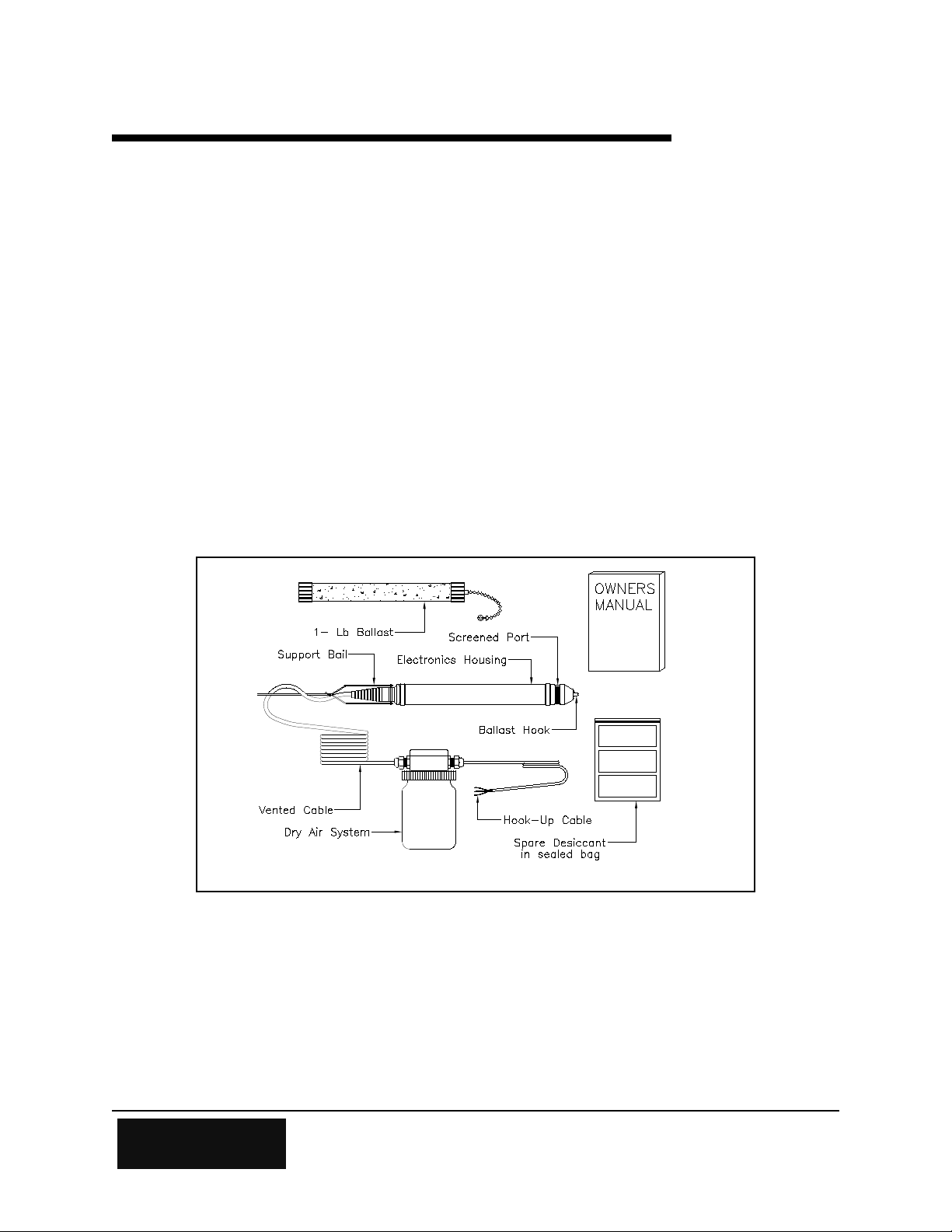
1.1 Unpacking the H-310
The following is a list of items you should have received:
Chapter 1
Unpacking the H-310
W
ATERLOG
Dry Air System
A one pound cement ballast
Three spare desiccant packs
The H-310 Owner's Manual
Stainless steel suspension cable and miscellaneous hardware (optional)
®
H-310 pressure transducer with polyethylene vented cable and H-305
Figure 1-1
Be sure that the vented cable is long enough to reach from the depth location selected to the
junction box of the dry air system. Also, be sure that the hook-up cable is long enough to reach
from the dry air system junction box to your data recorder.
H-310 Unpacking the H-310 1-1
Page 10

1.2 Checking the Model Number
Before installing your new WATERLOG® H-310, check the information on the label of the sensor
enclosure. Check the model number, the range, and the output type to be sure that you have
received the instrument you ordered. The label will look similar to the following:
Model: H-310
Range: 0-15 psi
Output: SDI-12
Input: 9.6 to 16.0 volts
S/N: 12345
This example shows that the W
ATERLOG
®
H-310-15 measures pressure within the range from
zero to 15 psi. This model works with a recording device that follows the SDI-12 protocol.
The full order number tells other details about the H-310. The key to the H-310 ordering system
is in Appendix B.
1.3 Testing the System
Before placing the H-310 in your selected location, you may wish to test the system by hooking
up the H-310 with your data recorder in the shop or lab, (as explained in this manual). Testing
the WATERLOG® H-310 in the shop or lab in a bucket of water, and observing the data recorder's
readings is good. This familiarizes the user with the H-310 and the data logger in a clear, easy to
work in, environment. You are also close to the telephone if questions should arise. However,
for this test to work correctly, you must run a wire from inside the bucket that comes in
contact with the water back to the chassis ground of the data recorder. This will insure
that there is a good earth ground connection. The purpose for this ground connection is to
remove AC coupled noise from the bucket.
1-2 Unpacking the H-310 H-310
Page 11

2.1 Installing the WATERLOG® H-310 and the H-305
Chapter 2
Installation
To install the W
at the desired location and connect the hook-up cable from the H-305 junction box to your data
logger.
2.1.1 Sensor Deployment
There are as many ways to deploy the H-310 as there are customers. However, as versatile as the
H-310 is, there are some site preparations and maintenance that must be considered.
1. If the sensor is to be clamped or tied down at a fixed location, the sensor must be where there
is no velocity flow. The WATERLOG® H-310 is a pressure sensor and changes in flow
correlate to changes in pressure. Thus, if the sensor is subjected to open flow, there is a good
chance your readings will be inconsistent. Key point: Use stilling wells, sand points, or
other "no flow" installation techniques. The result will be very accurate, reliable data.
2. The H-310 can be hung in well bores and float type stilling wells or conduits. If this is the
type of installation that is being done, the H-310 should be installed by suspending the sensor
not by its polyethylene vent cable, but by using a stainless steel drop cable and by using a
weighted ballast or sinker, such as the one that has been provided. The ballast will cause the
sensor to sink to the desired depth and will help the sensor to hang straight down. The
stainless cable and the miscellaneous hardware can be purchased from Design Analysis
Associates, or from a number of other sources.
ATERLOG
®
H-310 sensor and the H-305 dry air system, simply deploy the H-310
The polyethylene vent cable has an extremely large thermal coefficient of expansion. This
coupled with the fact that the polyethylene tubing will stretch with applied weight, make the use
of the stainless steel drop cable a must. Use of the stainless steel drop cable will insure long
term stability. THIS IS A MUST!!!
One end of the stainless steel tube is attached to the support bail on the sensor and the other end
is fastened to a fixed reference point at the surface. The ballast is attached to the ballast hook of
the sensor, as shown in Figure 2-1.
H-310 Installation 2-1
Page 12
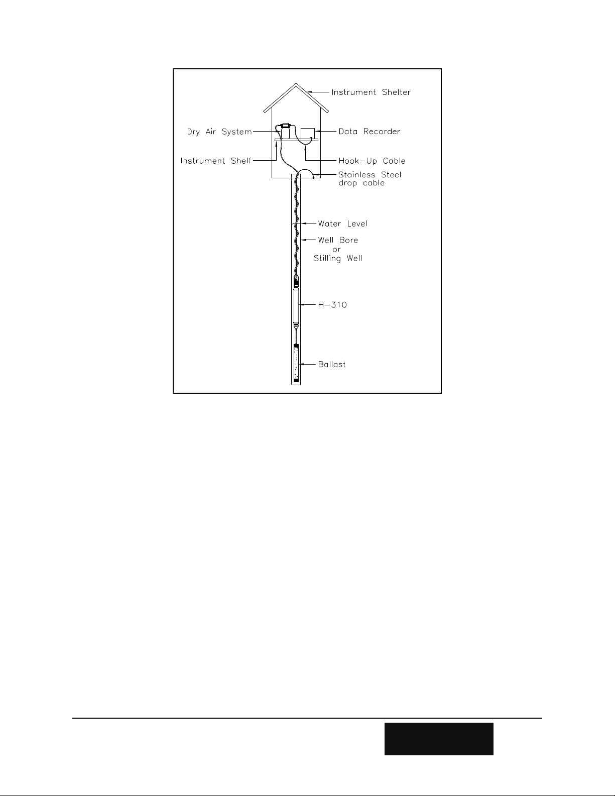
Figure 2-1
3. The H-305 dry air system should be placed in an easily accessible spot. This allows the user to
maintain the desiccant, and if needs be, the wiring inside the junction box.
The H-305 dry air system is designed to protect the sensor from moisture accumulation. The
desiccant inside the dry air system should be checked every 3 to 6 months. The desiccant bags
have a transparent strip which allows the condition of the desiccant to be visually checked. Dry
desiccant is dark blue and saturated desiccant will have turned pink. The desiccant packs can be
reused by drying them in an oven at 125F to 150F for 4 to 8 hours or until the desiccant returns
to a dark blue color.
2-2 Installation H-310
Page 13

2.1.2 Environmental Concerns
Through years of experience dealing with measuring in the environment, we have learned that
Mother Nature is very unforgiving to electronic equipment. There are several environmental
concerns with respect to installation and use of the H-310.
1. Although the H-310 is submersible, it cannot be frozen. Damage will occur to the sensor if
it is frozen. Transducers which are installed in geographical areas with harsh winters should
be removed for the winter unless they are deep enough in the water that there is no danger of
freezing. Ice may form around the vent tube without causing damage or performance
degradation. However, the vent tube should be placed so as to minimize the possibility of it
being ripped as the ice shifts or breaks up during times of thawing.
2. As with all plastics, the polyethylene vent tube is sensitive to ultraviolet (UV) light. If
subjected to intense UV light for extended periods of time, rotting of the tube will occur.
Whenever possible, precautions should be taken to protect the above-water portion of the vent
tube from sun light.
3. Experience has shown that if part of the enclosure of the H-310 is above the water and
exposed to sunlight (e.g. installed in shallow water), a temperature gradient can occur inside
of the enclosure which will cause a partial pressure on the reference side of the sensor. This
pressure will raise or lower the H-310s pressure reading depending on the polarity of the
partial pressure. This is a "Laws of Physics" problem not unique to W
ATERLOG
®
Series
transducers. It can easily be overcome by installing the transducer horizontally so that the
entire enclosure is covered by water.
2.3 Range of Stage
Use the following chart to determine the maximum depth at which the H-310 will measure
pressure accurately. Do not place the H-310 more than twice the rated depth for your model's
range, or the instrument will be damaged.
Model
Pressure Range Depth Range
*
Accuracy
H-310-05 zero to 05 psi zero to 11.53 ft. +0.002 ft.
H-310-15 zero to 15 psi zero to 34.60 ft. +0.007 ft
H-310-30 zero to 30 psi zero to 69.20 ft. +0.014 ft.
*NOTE: Depth calculations are derived from the standard equation that one psi is generated by a
column of water 27.680 inches deep at 39.4F.
H-310 Installation 2-3
Page 14

2.4 Connecting the Hook-up Cable
If the hook-up cable from the junction box to your data recorder needs to be modified or
changed, see Figure 2-2 and follow these steps:
Step 1- Remove the lid from the junction box by loosening the two corner screws.
Step 2- Loosen the gland nut on the data recorder end of the junction box.
Step 3- Pull enough hook-up cable to work with through the watertight fitting. Then strip the
PVC coating from the cable end (about two inches).
Step 4- Strip the coating from the end of each of the conductor wire (about one-eighth inch).
Now you are ready to connect the three wires and the shield inside the vented junction box.
Notice that the terminals in the junction box are numbered to show which wire should be put in
each slot.
Hook-up cable Vented cable
Slot 4 - Power Wire (Red) Slot 5 - Power Wire (Red)
Slot 3 - Ground Wire (Black) Slot 6 - Ground Wire (Black)
Slot 2 - Data Wire (White) Slot 7 - Data Wire (White)
Slot 1 - Shield Wire (No covering) Slot 8 - Shield Wire (No covering)
NOTE: If you are using your own hook-up cable, make certain you identify the color coding of
your wire before proceeding.
2-4 Installation H-310
Page 15

Figure 2-2
Step 5- With a small screw driver, loosen the screw of the terminal strip to open each slot where
you want to insert a wire.
Step 6- Insert the wires.
Step 7- Tighten the screw down while holding the wire in place.
Step 8- Check to make sure each wire is connected securely in the correct slot.
Step 9- Tighten the gland nut so it grips your hook-up cable tightly.
Step 10- Replace the lid and screw the lid down on the junction box.
Step 11- Check your desiccant packs. Replace if necessary.
H-310 Installation 2-5
Page 16

2.5 Connecting Your Data Recorder
Your selected data recorder must be capable of reading the type of signals (SDI-12 or RS-232)
output by your specific WATERLOG® model.
Connect the hook-up cable coming from the junction box to the appropriate port of your data
recorder, either SDI-12 or RS-232. Note: The RS-232 option will require that you use an H-
214 SDI-12 to RS-232 converter between your data recorder and the W
ATERLOG
®
H-310.
The output section of the H-310 electronics enclosure label will indicate what type of output
mode your sensor will operate in.
NOTE:
The shield in the hook-up cable must be connected to ground.
The H-310 requires that the water be at ground potential. Mother Nature takes care
of this in ground and surface water. The data recorder must also be earth grounded.
This is the responsibility of the user.
2-6 Installation H-310
Page 17

3.1 Operation
Chapter 3
Operation
The W
microprocessor automatically compensates for error due to offset, non-linearity, and temperature
changes. The H-310 outputs pressure and temperature measurements in psi units and degrees
centigrade.
SPECIAL NOTE: The WATERLOG® H-310 is a very sensitive instrument with special
temperature sensing circuitry. Thus, if you desire the most accurate readings from your
H-310, allow 10 to 15 minutes after installation for the system to come to a thermal
equilibrium with the submerging medium.
The WATERLOG® H-310 has advanced features that allow the user more flexibility than
previously in the WATERLOG® H-300. These features are as follows:
ATERLOG
1. Programmable slope and offset. This feature allows the user to send an extended
SDI-12 command from the data recorder or P.C. terminal program to the H-310 that
will change the pressure output units from psi to feet or meters or the units you choose.
The offset command allows the user to add to or subtract a fixed offset from the
output. This allows the data to be referenced to a datum point, or other reference
point.
2. Fast SDI mode. This mode allows the user to collect data at a 1 second interval
versus the standard 8 second interval. However, the +
be maintained in this mode. Also, the H-310 will be at maximum power consumption
continuously. This mode is set by using an extended SDI-12 command.
®
H-310 is easy to use and works with many data recorders. Its internal
0.02% FSO accuracy will not
3. Zero Offset Command. This extended command allows the user to perform an
automatic zero pressure calibration. After the sensor is removed from the water and
allowed to drain, the extended zero offset command will cause the H-310 to perform a
zero calibration measurement. The new zero offset value is stored in EEPROM
internal to the H-310. The sensor can be immediately returned to service. This
command can also be used while the sensor is in place to reference the zero reading to
where the sensor is located.
These extended commands are described in full detail in Appendix D of this manual.
H-310 Operation 3-1
Page 18

3.2 Reading Data from the H-310
Since data recorders differ widely, you must prepare your data recorder to receive and display the
H-310 data according to the recorder manufacturer's directions.
User requirements also differ. Users may program their data recorders individually for such
variables as sampling rates.
The following information is provided to help you customize your system according to the data
recorder you will use and your data requirements:
SDI-12. Program your data recorder to measure and record two values (pressure
and temperature) via the SDI-12 port. Your data recorder must issue an
M command, as explained in Appendix C. (Appendix C and
Appendix D give the command and response protocol used by SDI-12
ATERLOG
W
®
models.)
RS-232. Program your computer or data recorder to transmit a "break," then
record the resulting ASCII string sent by the sensor. The term "break" is
defined as a "marking" condition on the data line for a minimum of
8.5 ms. This definition can be found in the SDI-12 standard
specification.
3-2 Operation H-310
Page 19

Chapter 4
Maintenance
4.1 Maintenance
Sustained operation is almost maintenance-free. Our experience tells us moisture creates the
largest percentage of field problems. Therefore, monitoring the desiccant is of prime importance.
Desiccant in the H-305 dry air system should be changed periodically, normally every three to six
months.
4.2 H-305 Maintenance Procedure
Regular maintenance of the H-305 desiccant is imperative. Follow this step by step procedure
and refer to Figure 4-1 on the next page to maintain the desiccant.
Step 1- Remove large clear plastic jar.
Step 2- Remove Bladder/Desiccant chamber.
NOTE: You don't have to remove the bladder from the smaller plastic jar.
Step 3- Replace saturated desiccant packs with fresh dark blue packs.
Step 4- Inspect the bladder around the O-ring where it seals against it. If the bladder is torn or
faulty, replace it. Do not substitute with a non-quilted type plastic bag.
Step 5- Shape the bladder until it is approximately half-way inflated. This allows the
bladder to transmit future changes in atmospheric pressure. An under or over inflated
bladder will not transmit the proper atmospheric compensation down the vented cable.
Step 6- Reinstall the clear plastic jar. It will be necessary to gently pull and twist the
bladder at the bottom to clear the jar opening. Inspect around the top of the jar to make
sure that none of the bladder is caught in the threads of the lid.
H-310 Maintenance 4-1
Page 20

Figure 4-1 H-305 Dry Air System
4.3 Cleaning the Port Screen
Occasionally the port screen and the pressure ports may need to be cleaned, rinsed out or
replaced . Replacement screens are available if needed. Figure 4-2 below shows the location of
the stainless steel screen at the end of the sensor housing.
To remove the stainless steel screen follow these steps.
Step 1- Force the rubber bumper ring up onto the enclosure. This rubber ring may be stiff, but it
will move. Be careful not to tear the ring. Glycol on the rubber ring may be used to aid
you in this step.
Step 2- Slide the plastic slip ring back towards the rubber ring. The stainless steel screen
should now be free.
Step 3- Remove the stainless steel screen, under the stainless steel screen you will find a plastic
filter screen. This should be removed also.
4-2 Maintenance H-310
Page 21

Step 4- Rinse the pressure ports with water to clear mud and silt. You may want to swish the
H-310 in a bucket of water or in the stream it is monitoring to rinse out the pressure
ports.
CAUTION: Be careful not to create large pressures by using sticks and the like to push
debris out of the way. This may cause a plunger effect, and thus over
pressure the H-310. USE COMMON SENSE.
Step 5- Replace the plastic filter and the stainless steel screen. Position the joints of the two
screens 180 apart. The end of the stainless steel screen with a slight bend should be on
the outside. Compress the screen with a turning action and slip both screens into the
groove in the nose piece.
Step 6- Slide the plastic slip ring into place such that the screen fits inside the groove of the
ring. You may need to twist the screen slightly until it fits snugly in both grooves.
Step 7- Slip the rubber bumper back into place.
Figure 4-2 H-310 Nose piece/Stainless steel screen
H-310 Maintenance 4-3
Page 22

4.4 Maintaining Desiccant Packs
The desiccant inside the dry air system should be checked every 3 to 6 months. The desiccant
bags have a transparent strip which allows the condition of the desiccant to be visually checked.
Dry desiccant is dark blue and saturated desiccant will have turned pink. The desiccant packs
can be reused by drying them in an oven at 125F to 150F for 4 to 8 hours or until the desiccant
returns to a dark blue color.
4.5 Trouble Shooting
Our experience over the last 5 years with submersible sensors has taught us a lot about the
problems associated with field deployable equipment. While there are few things that can go
wrong with a H-310 sensor, here is a list of the most common problems.
No SDI-12 response
1- Check power and ground connections. Our experience shows that good power and
ground connections are the most important and the most overlooked.
2- Check pin out of Data Recorder for correct wiring.
H-310 Wiring Code
Red +12V
White Data
Black Ground
Shield Ground (must be connected)
Intermittent Data
1- Check your power and ground connections. Moisture over time will oxidize and
corrode connectors and pins.
2- Check the H-305 Desiccant packs. The intermittent data coming from the moisture is
beginning to accumulate at the sensor. If this is the case, you should contact Design
Analysis for instructions as how to proceed.
4-4 Maintenance H-310
Page 23

Appendix A
Specifications
Accuracy
(Maximum percent of error in measurement)
Pressure: Less than or equal to 0.02% of full
scale output (FSO) over
temperature range referenced to a
straight line stretched from zero psi
to maximum pressure.
Temperature: Internal temperature ±1
temperature range.
C over
Resolution
(Smallest change detectable in output signal)
Pressure: 1 part in 250,000 (0.0004%)
Temperature: 1 part in 250,000 (0.0004%)
Linearity
Less than 0.02% deviation from a straight line
referenced to end points.
Pressure Hysteresis
Less than 0.01% of FSO.
Long-term Stability
Accuracy drift is less than +0.05% of FSO per year.
Response Times
SDI-12: 8 second measurement sequence
RS-232C: 8 second measurement sequence
(both modes programmable to 1
second "fast measure")
Range
Pressure Depth
0 to 5 psi 0 to 11.53 ft.
0 to 15 psi 0 to 34.60 ft.
0 to 30 psi 0 to 69.20 ft.
Media Compatibility
Liquids and gases compatible with PVC, RTV and
stainless steel.
Pressure Port
Stainless steel screen with 149 micron filter, field
replaceable.
Power Supply
Voltage: 9.6 to 16.0 volts DC
Supply Current:
Sleep Mode: 1 mA maximum
Active (Measuring): 50 mA maximum
Dry Air System
Prevents moisture from condensing in the
submersible pressure transducer, provides
compensation for changes in atmospheric pressure
without impairing the sensor's accuracy.
SDI-12 Output
Baud Rate: 1200
Protocol: SDI-12, 7-bit even parity, 1 stop bit
Output Voltage Levels:
minimum high level: 3.5 volts
maximum low level: 0.8 volts
maximum cable length: 1000 ft.
RS-232C Output
(requires optional H-214)
Baud Rate: 1200
Protocol: RS-232C, 7-bit even parity, 1 stop bit
Mechanical Data
Material: PVC Barrel, Isoplast end caps, and
polyethylene vent tubing
Size: 1.425" maximum diameter x 10" long
Pressure Overload: Less than 2 times the
rated pressure.
Environmental Restrictions
Operating Range: 0 to 40 C
(non-freezing)
Compensated Range: 0 to 40 C
Storage: -10 to 55C
H-310 Appendix A Specifications A-1
Cables
Sensor Cable (H-310 to junction box): vented,
shielded, three-wire cable; 10 foot standard length
(longer lengths are available if required).
Warranty
The WATERLOG® H-310 is warranted against
defects in materials and workmanship for one year
from date of shipment.
Page 24

Page 25

Appendix B
Key to the Model Ordering System
H-310 - 0 1 5- G I - D - 0 1 0 0
Pressure Range Signal Output
(--5) 0-5 psi
(-15) 0-15 psi (D) SDI-12
(-30) 0-30 psi (R) RS-232
Configuration Cable
(GI) Gauge, Immersion Polyethylene, nnnn ft.
(GP) Gauge, 1/8" NPT-F For other vented tubing
please consult factory.
Note: The GP configuration WATERLOG®’s are for non-immersion applications.
H-310 Appendix B Key to the Model Ordering System B-1
Page 26

Page 27

Appendix C
SDI-12 Command and Response Protocol
C.1 SDI-12 Command and Response Protocol
This is a brief description of the Serial Digital Interface (SDI-12) Command and Response
protocol used by the W
ATERLOG
data format supported by the H-310.
Refer to the document "A SERIAL DIGITAL INTERFACE STANDARD FOR HYDROLOGIC
AND ENVIRONMENTAL SENSORS" for a complete description of the SDI-12 protocol.
Version 1.0 October, 1988 Coordinated by Campbell Scientific, Inc., Logan, Utah.
During normal communication, the data recorder sends an address together with a command to
the WATERLOG® H-310 sensor. The H-310 then replies with a "response". In the following
descriptions, SDI-12 commands and responses are enclosed in quotes. The SDI-12 address and
the command/response block terminators are defined as follows:
"a" Is the sensor address (0-9,*).
®
H-310 sensor. Included is a description of the commands and
Notes:
0 Is the default sensor address. Sensors will be initially programmed by the factory for this
address for use in single sensor systems.
1 - 9 Are addresses for additional sensors connected to the same SDI-12 bus.
A - Z Are additional addresses supported by the H-310.
* Is a printable ASCII "wild card" address which selects any sensor, regardless of its actual
address. This address is unique to the H-300, H-310 and H-350 sensors manufactured by
Design Analysis.
"!" Is the last character of a command block.
"<cr><lf>" Are carriage return (0D)hex and line feed (0A)hex characters. They are the last two
characters of a response block.
All command/responses are upper-case printable ASCII characters.
Commands must be terminated with a "!" character.
Responses are terminated with <cr><lf> characters.
The command string must be transmitted in a contiguous block with no gaps of more
than 1.66 milliseconds between characters.
All ASCII-Hex commands, arguments and data values are transmitted
most-significant-digit first.
H-310 Appendix C SDI-12 Command and Response Protocol C-1
Page 28

C.2 Initiate Measurement Command
Command Response Description
"aM!" "atttn<cr><lf>" Initiate measurement
"aM1!" - "aM9!" "atttn<cr><lf>" Additional measurement commands
Where :
a is the sensor address (0-9,*).
M (or M1 thru M9) are upper-case ASCII characters
ttt is a three digit integer (000-999) specifying the maximum time, in seconds, the sensor will take to
have measurement data available in its buffer.
n is a single digit integer (0-9) specifying the number of values that will be placed in the data buffer. If
"n" is zero (0), no data will be available using subsequent "D" commands.
The Initiate Measurement command causes a measurement sequence to be performed. Data
values generated in response to this command are stored in the sensor's buffer for subsequent
collection using "D" commands. The data will be retained in the sensor until another "M" or "V"
command is executed.
Upon completion of the measurement, a service request "a<cr><lf>" is sent to the data recorder
indicating the sensor data is ready. If the service request is not received properly before the
specified processing time has elapsed, the data recorder may wake the sensor with a break and
collect the data.
The following table lists the measure commands supported by the W
ATERLOG
®
H-310 and the
responses from the sensor.
H-310 supported Initiate Measurement commands:
Command Response Time Values Description
"aM!" "a0082<cr><lf>" 08 sec 2 Initiate pressure and
temperature measurement
"aM1!" "a0084<cr><lf>" 08 sec 4 Initiate diagnostic pressure and
temperature measurement
"aM2!" "a0081<cr><lf>" 08 sec 1 Initiate temperature only
measurement
"aM3!" "a0081<cr><lf>" 08 sec 1 Initiate pressure only
measurement
"aM4!" "a0081<cr><lf>" 08 sec 1 Initiate +12V power supply
measurement
Response times are 1 second in "fast measure" mode, see Appendix D.
C-2 Appendix C SDI-12 Command and Response Protocol H-310
Page 29

C.3 INITIATE VERIFY COMMAND
Command Response Description
"aV!" "atttn<cr><lf>" Initiate verify sequence
Where:
a Is the sensor address (0-9,*).
V Is an upper-case ASCII character.
ttt Is a three digit integer (000-999) specifying the maximum time, in seconds, the sensor will take to
have data available in its buffer.
n Is a single digit integer (0-9) specifying the number of values that will be placed in the data buffer.
If "n"is zero (0), no data will be available using subsequent "D" commands.
The Initiate Verify command causes a verify sequence to be performed. The result of this
command is similar to the "aM!" command except that the values generated are fixed test data
and diagnostic checksum test results. The data generated in response to this command is placed
in the sensor's buffer for subsequent collection using "D" commands. The data will be retained in
the sensor until another "M" or "V" command is executed.
The following table shows the command and response to the verify command.
H-310 response to a "aV!" command:
Command Response Time Values Description
"aV!" "a0034<cr><lf>" 3 sec 4 Return fixed data and diagnostic
data for testing purposes.
C.4 Send Data Command
Command Response
"aD0!" through "aD9!" "apd.d ... pd.d<cr><lf>"
Where:
a Is the sensor address (0-9,*).
D0..D9 Are upper-case ASCII characters.
p Is a polarity sign (+ or -)
d.d Represents numeric digits before and/or after the decimal. A decimal may be used in any
position in the value after the polarity sign. If a decimal is not used, it will be assumed to be
after the last digit.
For example: +3.29 +23.5 -25.45 +300
H-310 Appendix C SDI-12 Command and Response Protocol C-3
Page 30

The Send Data command returns sensor data generated as the result of previous "aM!" or "aV!"
commands. Values returned will be sent in 33 characters or less. The sensor's data buffer will
not be altered by this command.
If the number of values returned by a "aD0!" command is less than the number specified by the
result of the previous "M" or "V" command, the rest of the data must be collected using "aD1",
"aD2!" .... and so on until all values specified have been collected.
If one or more values were specified and a "aD0!" returns no data, it means that the measurement
was aborted and a new "M" command must be sent.
The Following table is a listing of the responses to the Send Data command supported by the
ATERLOG
W
H-310 response to a "aD0!" command:
Note: "aD1!" - "aD9!" commands not supported (or needed)
Previous command Response format
"aM!" a+xxx.xxx+yy.y<cr><lf>
"aM1!" a+xxx.xxx+yy.y+XXXXX+YYYYY<cr><lf>
"aM2!" a+yy.y<cr><lf>
"aM3!" a+xxx.xxx<cr><lf>
"aM4!" a+zz.z<cr><lf>
"aV!" a+123.456+78.9+p+q<cr><lf>
®
H-310.
Key Measurement Units
xxx.xxx Current Pressure Pounds-per-Square Inch (PSI).
yy.y Current Temperature Centigrade (C).
zz.z Input Voltage Volts (V)
XXXXX Current Pressure Raw reading
YYYYY Current Temperature Raw reading
p ROM checksum test 0 = Failed, 1 = Passed
q COP status 0 = Off, 1 = On
C.5 Send Acknowledge Command
Command Response
"a!" "a<cr><lf>"
Where:
a Is the sensor address (0-9,*).
The Send Acknowledge command returns a simple status response which includes address of the
sensor. Any measurement data in the sensor's buffer is not disturbed.
C-4 Appendix C SDI-12 Command and Response Protocol H-310
Page 31

C.6 Send Identification Command
Command Response
"aI!" "allccccccccmmmmmmvvvxx...xx<cr><lf>"
Where:
a Is the sensor address (0-9,*).
I Is an upper-case ASCII character.
ll Is the SDI-12 version compatibility level, e.g. version 1.0 is represented as "10".
cccccccc Is an 8 character vendor identification to be specified by the vendor and usually in the form of
a company name or its abbreviation.
mmmmmm Is a 6 character field specifying the sensor model number.
vvv Is a 3 character field specifying the sensor version number.
xx...xx Is an optional field of up to a maximum of 13 characters to be used for serial number or other
specific sensor information not relevant to operation of the data recorder.
The Send Identification command responds with sensor vendor, model, and version data. Any
measurement data in the sensors buffer is not disturbed.
H-310 Response to a "aI!" command:
"a10 DAA H-310vvvS#nnnnnnVkkk<cr><lf>"
H-310 implementation of optional field:
S#nnnnnnVkkk (12 bytes total)
Where:
"nnnnnn" is a six character sensor serial number
"kkk" is a three digit sensor firmware revision level
H-310 Appendix C SDI-12 Command and Response Protocol C-5
Page 32

Page 33

H-310 Extended Commands
D.1 Change Sensor Address
Command Response Description
"aXAn!" "atttn<cr><lf>" Change sensor address
Where:
a Is the current (old) sensor address (0-9,A-Z, *). An ASCII "*" may be used as a "wild card"
address if the current address is unknown and only one sensor is connected to the bus.
XA Are upper-case ASCII characters.
n Is the new sensor address to be programmed (0-9,A-Z).
ttt Is a three digit integer (000-999) specifying the maximum time, in seconds, the sensor will take to
complete the command and have data available in its buffer.
n is a single digit integer (0-9) specifying the number of values that will be placed in the data buffer.
If "n" is zero (0), no data will be available using subsequent "D" commands.
Appendix D
The Change Sensor Address command allows the sensor address to be changed. The address is
stored in non-volatile EEPROM within the sensor. The H-310 will not respond if the command
was bad, the address was out of range, or the EEPROM programming operation failed.
NOTE: To verify the new address use the "Identify Command."
Example of a "Change Sensor Address" command:
Command Response Time Values Description
"aXA2!" "a0020<cr><lf>" 2 sec 0 Change sensor address to "2"
H-310 Appendix D H-310 Extended Commands D-1
Page 34

D.2 Zero Offset Command
Command Response Description
"aXZ!" "atttn<cr><lf>" Zero the sensor offset
Where:
a Is the sensor address (0-9,*).
XZ Are upper-case ASCII characters.
ttt Is a three digit integer (000-999) specifying the maximum time, in seconds, the sensor will take to
have data available in its buffer.
n Is a single digit integer (0-9) specifying the number of values that will be placed in the data buffer.
If "n" is zero (0), no data will be available using subsequent "D" commands.
The Zero Offset command measures the current pressure and automatically adjusts the sensor's
offset to produce a zero output value. The new offset is stored in non-volatile EEPROM within
the sensor. The data generated in response to this command is the new value. The user must
manually pull the sensor from the water or position it at the desired zero reference before issuing
this command.
Example of a "Zero Offset" command:
Command Response Time Values Description
"aXZ!" "a0081<cr><lf>" 8 sec 1 Zero the sensor offset
D-2 Appendix D H-310 Extended Commands H-310
Page 35

D.3 Write "User Units Slope" Command
Command Response Description
"aXWSddd!" "atttn<cr><lf>" Write user units slope coefficient
Where:
a Is the sensor address (0-9,*)
XWS Are upper-case ASCII characters
ddd Is a the new user units slope value. The input format is very flexible. Some examples are shown
below.
20.095
0.195
7.984E+10
167.824E5
005.9357E-7
500
ttt Is a three digit integer (000-999) specifying the maximum time, in seconds, the sensor will take to
complete the command and have data available in its buffer.
n Is a single digit integer (0-9) specifying the number of values that will be placed in the data buffer.
The Write User Slope Command loads the "Users Units Slope" coefficient term. The new value
is stored in non-volatile EEPROM within the sensor. Once the new slope term is written to the
EEPROM a copy is sent to the sensor data buffer for verification. This verification is done by
using the "D" command. To verify the current "User Units Slope"
any other time use the "Read User Units Slope" command.
Example of a "Write User Units Slope" command:
Command Response Time Values Description
"aXWS1.234!" "a0021<cr><lf>" 2 sec 1 Write user units slope
coefficient
H-310 Appendix D H-310 Extended Commands D-3
Page 36

D.4 Write "User Units Offset" Command
Command Response Description
"aXWOddd!" "atttn<cr><lf>" Write user units offset coefficient
Where:
a Is the sensor address (0-9,*).
XWO Are upper-case ASCII characters.
ddd Is a the new user offset value. The input format is very flexible. Some examples are shown
below.
20.095
0.195
7.984E+10
167.824E5
005.9357E-7
500
ttt Is a three digit integer (000-999) specifying the maximum time, in seconds, the sensor will
take to complete the command and have data available in its buffer.
n Is a single digit integer (0-9) specifying the number of values that will be placed in the data
buffer.
The Write User Offset Command loads the "Users Units Offset" coefficient term. The new value
is stored in non-volatile EEPROM within the sensor. With the new offset value now written into
EEPROM, a copy of this value is placed in the sensor data buffer for verification. The
verification is carried out by using the "D" command. To verify the "User Units Offset" at any
other time use the "Read User Units Offset" command.
Example of a "Write User Units Offset" command:
"aXWO12.34!" "a0021<cr><lf>" 2 sec 1 Write user units offset
Command Response Time Values Description
coefficient
D-4 Appendix D H-310 Extended Commands H-310
Page 37

D.5 Read "User Units Slope" Command
Command Response Description
"aXRS!" "atttn<cr><lf>" Load sensor buffer with User Slope
Where:
a Is the sensor address (0-9,*).
XRS Are upper-case ASCII characters
ttt Is a three digit integer (000-999) specifying the maximum time, in seconds, the sensor will take to
complete the command and have data available in its buffer.
n Is a single digit integer (0-9) specifying the number of values that will be placed in the data buffer.
The Read User Units Slope Command reads the "Users Units Slope" coefficient term. The value
is read from non-volatile EEPROM within the sensor and loaded into the sensor data buffer.
With the data in the sensor data buffer now you can view the current slope by issuing a "D"
command.
Example of a "User Units Slope" command:
"aXRS!" "a0021<cr><lf>" 2 sec 1 Load sensor buffer with the User
Command Response Time Values Description
Units Slope coefficient
D.6 Read "User Units Offset" Command
Command Response Description
"aXRO!" "atttn<cr><lf>" Load sensor buffer with User Offset
Where:
a Is the sensor address (0-9,*).
XRO Are upper-case ASCII characters
ttt Is a three digit integer (000-999) specifying the maximum time, in seconds, the sensor will take to
complete the command and have data available in its buffer.
n Is a single digit integer (0-9) specifying the number of values that will be placed in the data buffer.
The Read User Units Offset Command reads the "Users Units Offset" coefficient term. The
value is read from non-volatile EEPROM within the sensor and loaded into the sensor data
H-310 Appendix D H-310 Extended Commands D-5
Page 38

buffer. With the data in the sensor data buffer now you can view the current slope by issuing a
"D" command.
Example of a "User Units Offset" command:
Command Response Time Values Description
"aXRO!" "a0021<cr><lf>" 2 sec 1 Load sensor buffer with the
User Units Offset coefficient
D.7 Change Sensor Output Mode
The change sensor output mode commands facilitate the changing of the sensors output mode.
The default mode is 8 second SDI-12 with the option of switching to 1 second SDI-12
measurements.
Standard RS-232 and looping RS-232 outputs are also possible on standard H-310s. These
outputs require additional hardware and instructions. Please consult DAA for details on the RS232 output options.
D.7.1 Query Sensor Speed Command
Command Response Description
"aXSQ!" "a,ccc,fff,sss<cr><lf>" Load sensor buffer with sensor speed status
Where:
a Is the sensor address (0-9,*)
XSQ Are upper-case ASCII characters
ccc Is the current sensor measurement speed (in seconds)
fff Is the fast mode measurement speed (in seconds)
sss Is the slow mode measurement speed (in seconds)
Example of a "Query Sensor Speed" command:
Command
"aXSQ!" "a,008,001,008<CR><LF>"
Response
| | +-Slow Mode
| +-----Fast Mode
+---------Current Mode
The query sensor speed command allows the user to interrogate the H-310 to determine the
current mode status.
D.7.2 Set Sensor Measurement Speed Fast
D-6 Appendix D H-310 Extended Commands H-310
Page 39

Command Response Description
"aXSF!" "a<cr><lf>" Set sensor measurement speed to fast
Where:
a Is the sensor address (0-9,*).
XSF Are upper-case ASCII characters.
Example of a "Set Sensor Measurement Speed Fast" command:
Command
"aXSF!" "a<CR><LF>"
Response
The set sensor measurement speed fast command causes the sensor to execute low resolution
measurements and make data available in 1 second.
NOTE: The fast measure mode is not a low power mode. The sensor remains powered at
all times in this mode. However, in this mode data can be collected at a two
second interval.
D.7.3 Set Sensor Measurement Speed Slow
Command Response Description
"aXSS!" "a<cr><lf>" Set sensor measurement speed to slow
Where:
a Is the sensor address (0-9,*).
XSS Are upper-case ASCII characters.
Example of a "Set Sensor Measurement Speed Slow" command:
Command Response
"aXSS!" "a<CR><LF>"
The set sensor measurement speed slow command causes the sensor to execute high resolution
measurements and make data available in 8 seconds. This is the default setting.
H-310 Appendix D H-310 Extended Commands D-7
Page 40

 Loading...