


FG6140T403NOV
Whirlpool FG6140T403NOV, FG6130T303NOV, FG1F5050T4NOV, FG6150S403NOV, FG6130S303NOV Installation And Use Manual
...
TM
HEATERS
Gas Water Heater
with the Flame Lock TM
Safety System
WARNING: If the information in these
instructions is not followed exactly, a fire
or explosion may result causing property
damage, personal injury or death.
Do not store or use gasoline or other
flammable vapors and liquids in the
vicinity of this or any other appliance.
WHAT TO DO IF YOU SMELL GAS
• Do not try to light any appliance.
+ Do not touch any electrical switch;
do not use any phone in your
building.
+ Immediately call your gas supplier
from a neighbor's phone. Follow the
gas supplier's instructions.
+ If you cannot reach your gas
supplier, call the fire department.
Installation and service must be performed
by a qualified installer, service agency or
the gas supplier.
Installation
Instructions and
Use & Care Guide
To obtain technical, warranty, or service assistance during or
after the installation of this water heater, call toll free:
1-877-817-6750
When calling for assistance, please have the following
information ready:
I. Model number
2. 7 Digit product number
3. Serial number
4. Date of installation
Table of Contents ...................................................... 2
6510233
September 2001

Your safety and the safety of others are very important.
We have provided many important safety messages in this manual and on your appliance. Always read and obey all
safety messages.
This is the safety alert symbol.
This symbol alerts you to potential hazards that can kill or hurt you and others.
All safety messages will follow the safety alert symbol and either the word "DANGER" or
"WARNING" These words mean:
You can be killed or seriously injured if you don't
immediately follow instructions.
You can be killed or seriously injured if you don't
follow instructions.
All safety messages will tell you what the potential hazard is, tell you how to reduce the chance of injury, and tell you
what can happen if the instructions are not followed.
Important Instructions
• Do not use this appliance if any part has been under water. Immediately call a qualified service technician. Water
heaters subjected to flood conditions or anytime the gas controls, main burner or pilot have been submerged in
water require replacement of the entire water heater.
• Hydrogen gas can be produced in a hot water system that has not been used for a long period of time (generally
two weeks or more). Hydrogen gas is extremely flammable and can ignite when exposed to a spark or flame. To
prevent the possibility of injury under these conditions, we recommend the hot water faucet be opened for several
minutes at the kitchen sink before using any electrical appliance which is connected to the hot water system. If
hydrogen is present, there will probably be an unusual sound such as air escaping through the faucet as water
begins to flow. Do not smoke or have any open flame near the faucet at the time it is open.
The California Safe Drinking Water and Toxic Enforcement Act requires the Governor of California to publish a list of
substances known to the State of California to cause cancer, birth defects, or other reproductive harm, and requires
businesses to warn of potential exposure to such substances.
Warning: This product contains a chemical known to the State of California to cause cancer, birth defects, or other
reproductive harm.
This appliance can cause low-level exposure to some of the substances listed, including formaldehyde, carbon
monoxide, and soot.
PAGE
Water Heater Safety .................................................................... 1-2
Installing Your Gas Water Heater ................................................ 3-16
Unpacking the Water Heater ....................................................... 3
Location Requirements .............................................................. 4
Gas Supply ................................................................................. 6
Combustion Air Supply and Ventilation ....................................... 7
Water System Piping ................................................................ 12
Installation Checklist ................................................................ 16
Operating YourWater Heater .................................................... 17-19
Lighting Instructions ....................................................................... 17
Operational Conditions ............................................................ 19
Maintenance of YourWater Heater ..................................... 20-24
Trouble Shooting Chart ............................................................ 25-26
Repair Parts Illustration ............................................................ 27-28
I ;TALL! YOU GAS EATE
Consumer information
This water heater is design-certified by CSA
International as a Category I, non-direct vented water
heater which takes its combustion air either from the
installation area or from air ducted to the unit from the
outside.
This water heater must be installed according to all
local and state codes or in the absence of local and
state codes with the "National Fuel Gas Code", ANSI
Z223.1 (NFPA 54)- latest edition. This is available from
the following:
American Gas Association
1515 Wilson Boulevard
Arlington, VA22209
National Fire Protection Agency
1 Batterymarch Park
Quincy, MA02269
Check your phone listings for the local authorities
having jurisdiction over your installation.
Consumer Responsibilities
This manual has been prepared to acquaint you with
the installation, operation and maintenance of your gas
water heater and provide important safety information in
these areas.
Read all of the instructions thoroughly before
attempting the installation or operation of this water
heater. Keep this manual for future reference.
Service to the Flame Lock TM safety system should
only be performed by a qualified service technician.
The manufacturer of this water heater will not be liable
for any damages caused by failure to comply with the
installation and operating instructions outlined in this
manual.
If you lack the necessary skills required to properly
install this water heater or you have difficulty following
the instructions, you should not proceed but have a
qualified person perform the installation of this water
heater. Massachusetts code requires this water heater
to be installed in accordance with Massachusetts
Plumbing and Fuel Gas Code 248 CMR section 2.00
and 5.00.
A data plate identifying your water heater can be found
next to the gas control valve/thermostat. When referring
to your water heater always have the information listed
on the data plate readily available.
Unpacking the Water Heater
Excessive Weight Hazard
Use two or more people to move and
install water heater.
Failure to do so can result in back or
other injury.
Removing Packaging Materials
Important: Do not remove any permanent instructions,
labels, or the data label from outside of the water heater
or on the inside of panels.
,, Remove exterior packaging and place installation
components aside.
,, Inspect all parts for damage prior to installation and
start-up.
,, Completely read all instructions before attempting
to assemble and install this product.
,, After installation, dispose of packaging material in
the proper manner.
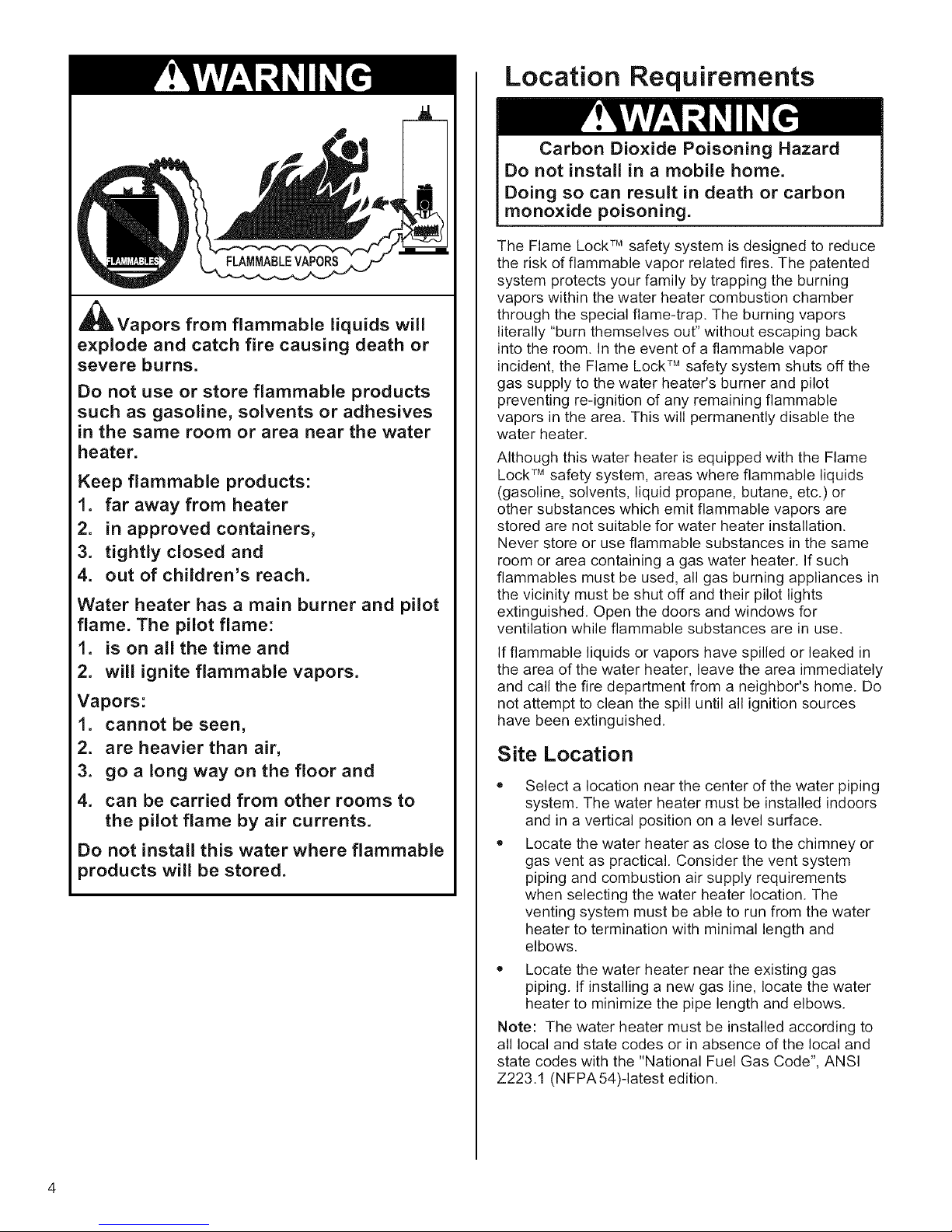
_lLVapors from flammable liquids will
explode and catch fire causing death or
severe burns.
Do not use or store flammable products
such as gasoline, solvents or adhesives
in the same room or area near the water
heater.
Keep flammable products:
1. far away from heater
2. in approved containers,
3. tightly closed and
4. out of children's reach.
Water heater has a main burner and pilot
flame. The pilot flame:
1. is on all the time and
2. will ignite flammable vapors.
Vapors:
1. cannot be seen,
2. are heavier than air,
3. go a long way on the floor and
4. can be carried from other rooms to
the pilot flame by air currents.
Do not install this water where flammable
products will be stored.
Location Requirements
Carbon Dioxide Poisoning Hazard
Do not install in a mobile home.
Doing so can result in death or carbon
monoxide poisoning.
The Flame Lock TM safety system is designed to reduce
the risk of flammable vapor related fires. The patented
system protects your family by trapping the burning
vapors within the water heater combustion chamber
through the special flame-trap. The burning vapors
literally "burn themselves out" without escaping back
into the room. In the event of a flammable vapor
incident, the Flame Lock TM safety system shuts off the
gas supply to the water heater's burner and pilot
preventing re-ignition of any remaining flammable
vapors in the area. This will permanently disable the
water heater.
Although this water heater is equipped with the Flame
Lock TM safety system, areas where flammable liquids
(gasoline, solvents, liquid propane, butane, etc.) or
other substances which emit flammable vapors are
stored are not suitable for water heater installation.
Never store or use flammable substances in the same
room or area containing a gas water heater. If such
flammables must be used, all gas burning appliances in
the vicinity must be shut off and their pilot lights
extinguished. Open the doors and windows for
ventilation while flammable substances are in use.
If flammable liquids or vapors have spilled or leaked in
the area of the water heater, leave the area immediately
and call the fire department from a neighbor's home. Do
not attempt to clean the spill until all ignition sources
have been extinguished.
Site Location
Select a location near the center of the water piping
system. The water heater must be installed indoors
and in a vertical position on a level surface.
Locate the water heater as close to the chimney or
gas vent as practical. Consider the vent system
piping and combustion air supply requirements
when selecting the water heater location. The
venting system must be able to run from the water
heater to termination with minimal length and
elbows.
* Locate the water heater near the existing gas
piping. If installing a new gas line, locate the water
heater to minimize the pipe length and elbows.
Note: The water heater must be installed according to
all local and state codes or in absence of the local and
state codes with the "National Fuel Gas Code", ANSI
Z223.1 (NFPA54)-Iatest edition.
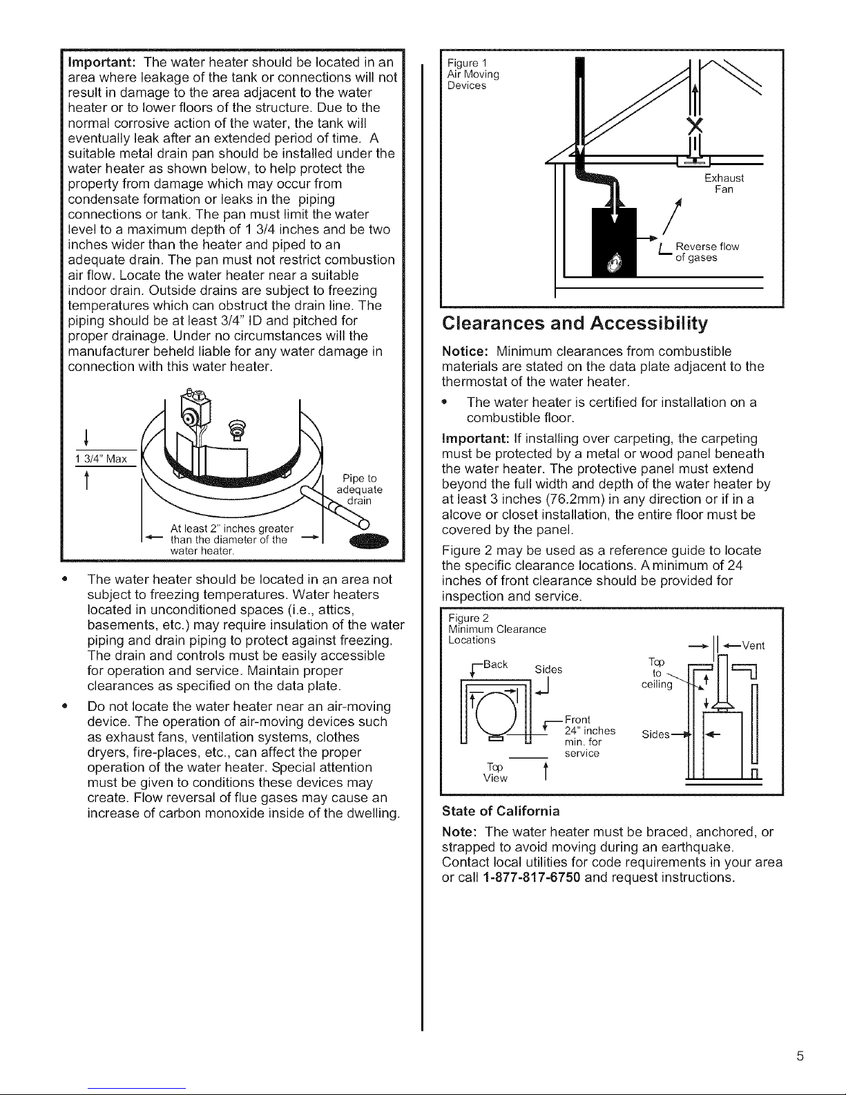
Important:Thewaterheatershouldbelocatedinan
areawhereleakageofthetankorconnectionswillnot
resultindamagetotheareaadjacenttothewater
heaterortolowerfloorsofthestructure.Duetothe
normalcorrosiveactionofthewater,thetankwill
eventuallyleakafteranextendedperiodoftime.A
suitablemetaldrainpanshouldbeinstalledunderthe
waterheaterasshownbelow,tohelpprotectthe
propertyfromdamagewhichmayoccurfrom
condensateformationorleaksinthe piping
connectionsortank.Thepanmustlimitthewater
leveltoa maximumdepthof13/4inchesandbetwo
incheswiderthantheheaterandpipedtoan
adequatedrain.Thepanmustnotrestrictcombustion
airflow.Locatethewaterheaternearasuitable
indoordrain.Outsidedrainsaresubjecttofreezing
temperatureswhichcanobstructthedrainline.The
pipingshouldbeatleast3/4"IDandpitchedfor
properdrainage.Undernocircumstanceswillthe
manufacturerbeheldliableforanywaterdamagein
connectionwiththiswaterheater.
1 3/4" Max
t
At least 2" inches greater
than the diameter of the "--_
water heater.
,, The water heater should be located in an area not
subject to freezing temperatures. Water heaters
located in unconditioned spaces (i.e., attics,
basements, etc.) may require insulation of the water
piping and drain piping to protect against freezing.
The drain and controls must be easily accessible
for operation and service. Maintain proper
clearances as specified on the data plate.
• Do not locate the water heater near an air-moving
device. The operation of air-moving devices such
as exhaust fans, ventilation systems, clothes
dryers, fire-places, etc., can affect the proper
operation of the water heater. Special attention
must be given to conditions these devices may
create. Flow reversal of flue gases may cause an
increase of carbon monoxide inside of the dwelling.
Pipe to
adequate
drain
Figure 1
Air Moving
Devices
Exhaust
Fan
/
L Reverse flow
of gases
Clearances and Accessibility
Notice: Minimum clearances from combustible
materials are stated on the data plate adjacent to the
thermostat of the water heater.
,, The water heater is certified for installation on a
combustible floor.
Important: If installing over carpeting, the carpeting
must be protected by a metal or wood panel beneath
the water heater. The protective panel must extend
beyond the full width and depth of the water heater by
at least 3 inches (76.2mm) in any direction or if in a
alcove or closet installation, the entire floor must be
covered by the panel.
Figure 2 may be used as a reference guide to locate
the specific clearance locations. A minimum of 24
inches of front clearance should be provided for
inspection and service.
Figure 2
Minimum Clearance
Locations
vi"-Back Sides
CTI_i°Pn___
service
II* Vent
si es- lFI!
T® l
View
State of California
Note: The water heater must be braced, anchored, or
strapped to avoid moving during an earthquake.
Contact local utilities for code requirements in your area
or call 1-877-817-6750 and request instructions.
Gas Supply
Explosion Hazard
Use a new AGA or CSA approved gas
supply line.
Install a shut-off valve.
Do not connect a natural gas water
heater to a L.P. Gas Supply.
Failure to follow these instructions can
result in death, explosion, or carbon
monoxide poisoning.
OBSERVE ALL GOVERNING CODES AND ORDINANCES.
Gas Requirements
Read the data plate to be sure the water heater is
made for the type of gas you will be using in your
home. This information will be found on the data plate
located near the gas control valve. If the information
does not agree with the type of gas available, do not
install or light. Call your dealer.
Note: An odorant is added by the gas supplier to the
gas used by this water heater. This odorant may fade
over an extended period of time. Do not depend upon
this odorant as an indication of leaking gas.
Gas Piping
The gas piping must be installed according to all local
and state codes or in absence of local and state codes
with the "National Fuel Gas Code", ANSI Z223.1
(NFPA54)-Iatest edition.
Tables 1 and 2 on page 7 are provided as a sizing
reference for commonly used gas pipe materials.
Consult the "National Fuel Gas Code" for the
recommended gas pipe size of other materials.
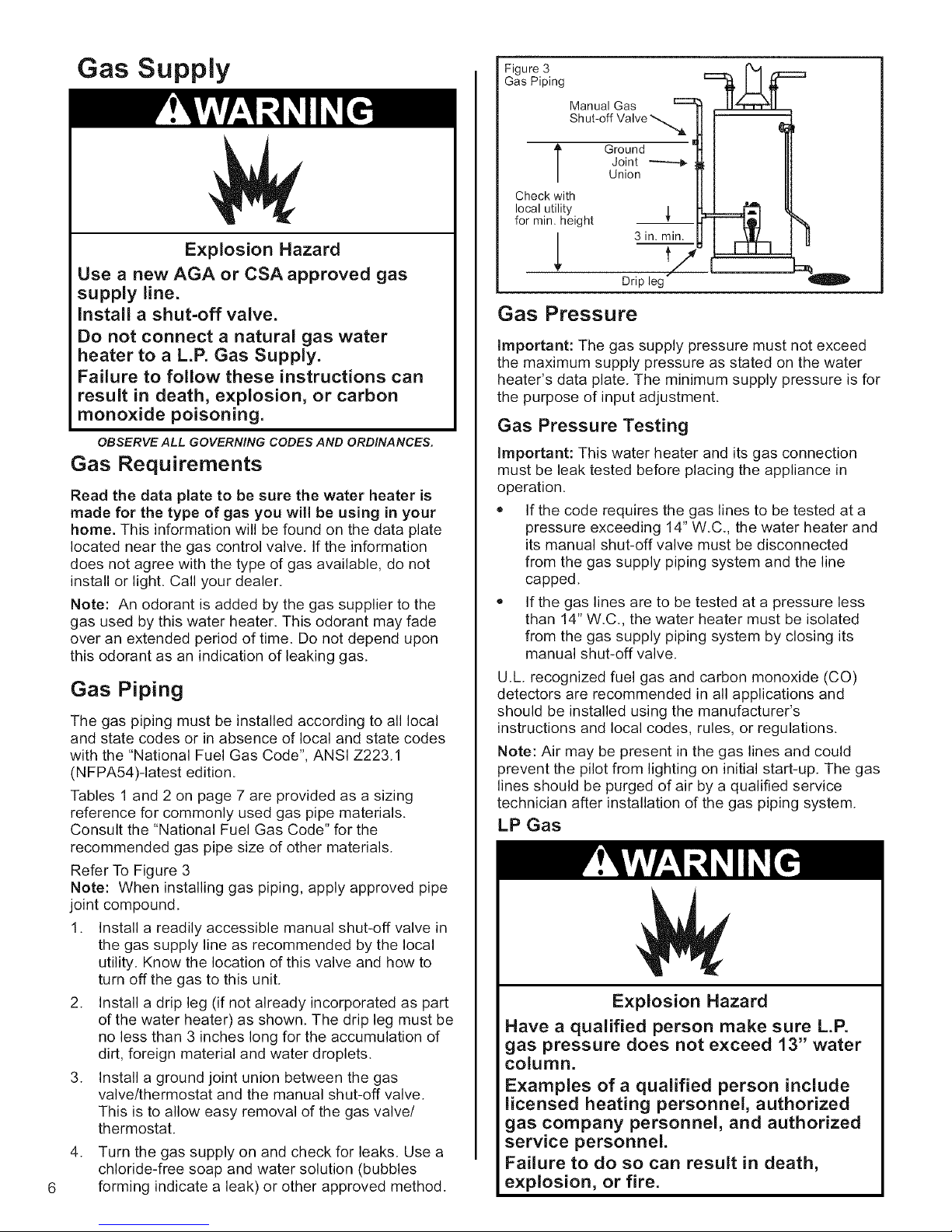
Refer To Figure 3
Note: When installing gas piping, apply approved pipe
joint compound.
1. Install a readily accessible manual shut-off valve in
the gas supply line as recommended by the local
utility. Know the location of this valve and how to
turn off the gas to this unit.
2. Install a drip leg (if not already incorporated as part
of the water heater) as shown. The drip leg must be
no less than 3 inches long for the accumulation of
dirt, foreign material and water droplets.
3. Install a ground joint union between the gas
valve/thermostat and the manual shut-off valve.
This is to allow easy removal of the gas valve/
thermostat.
.
Turn the gas supply on and check for leaks. Use a
chloride-free soap and water solution (bubbles
forming indicate a leak) or other approved method.
Figure 3
Gas Piping
Manual Gas c:::3
Shut-off Valve
Ground
[
Check with
local utility
for min. height
1
Joint _---_
Union
3 in. min.
t/
Drip leg"
Gas Pressure
Important: The gas supply pressure must not exceed
the maximum supply pressure as stated on the water
heater's data plate. The minimum supply pressure is for
the purpose of input adjustment.
Gas Pressure Testing
Important: This water heater and its gas connection
must be leak tested before placing the appliance in
operation.
• If the code requires the gas lines to be tested at a
pressure exceeding 14" W.C., the water heater and
its manual shut-off valve must be disconnected
from the gas supply piping system and the line
capped.
_, If the gas lines are to be tested at a pressure less
than 14" W.C., the water heater must be isolated
from the gas supply piping system by closing its
manual shut-off valve.
U.L recognized fuel gas and carbon monoxide (CO)
detectors are recommended in all applications and
should be installed using the manufacturer's
instructions and local codes, rules, or regulations.
Note: Air may be present in the gas lines and could
prevent the pilot from lighting on initial start-up. The gas
lines should be purged of air by a qualified service
technician after installation of the gas piping system.
LP Gas
Explosion Hazard
Have a qualified person make sure L.R
gas pressure does not exceed 13" water
column.
Examples of a qualified person include
licensed heating personnel, authorized
gas company personnel, and authorized
service personnel.
Failure to do so can result in death,
explosion, or fire.

Table 1
Natural Gas Pipe Capacity Table (Cu. Ft./hr)
Capacity of gas pipe of different diameters and lengths in cu. ft. per hr. with pressure drop of 0.3 in. and specific gravity
of 0.60 (natural gas).
Nominal Iron Pipe Length of Pipe, Feet
Size, in. 10 20 30 40 50 60 70 80 90 100 125 150 175 200
1/2 132 92 73 63 56 50 46 43 40 38 34 31 28 26
3/4 278 190 152 130 115 105 96 90 84 79 72 64 59 55
1 520 350 285 245 215 195 180 170 160 150 130 120 110 100
1-1/4 1050 730 590 500 440 400 370 350 320 305 275 250 225 210
I-I/2 1600 1100 890 760 670 610 560 530 490 460 410 380 350 320
After the length of pipe has been determined, select the pipe size which will provide the minimum cubic feet per hour
required for the gas input rating of the water heater. By formula:
Cu. Ft. Per Hr. Required=
The gas input of the water heater is marked on the water heater data plate. The heating value of the gas (BTU/FT _)
may be determined by consulting the local natural gas utility.
Gas Input of Water Heater (BTU/HR)
Heating Value of Gas (BTU/FT 3)
Table 2
LP Gas Capacity Table
Maximum capacity of pipe in thousands of BTU per hour of undiluted liquefied petroleum gases (at 11 inches water
column pressure). Based on a Pressure Drop of 0.5 Inch Water Column.
Nominal Iron Pipe Length of Pipe, Feet
Size, in. 10 20 30 40 50 60 70 80 90 100 125 150
1/2 275 189 152 129 114 103 96 89 83 78 69 63
3/4 576 393 315 267 237 217 196 185 173 162 146 132
1 1071 732 590 504 448 409 378 346 322 307 275 252
I-1/4 2205 1496 1212 1039 913 834 771 724 677 630 567 511
Example: Input BTU requirement of the water heater I00,000 BTUH
Total pipe length, 80 feet = 3/4" IPS required.
Additional tables are available in the latestedition of the "National Fuel Gas Code", ANSI Z223.1
Combustion Air Supply and
Ventilation
Carbon Monoxide Warning
Follow all the local and state codes or in
absence of local and state codes the
"National Fuel Gas Code", ANSI Z223.1
(NFPA 54)- latest edition to properly
install vent system.
Failure to do so can result in death,
explosion, or carbon monoxide poisoning.
Important: Air for combustion and ventilation must not
come from a corrosive atmosphere. Any failure due to
corrosive elements in the atmosphere is excluded from
warranty coverage.
The following types of installation (but not limited to the
following) will require outdoor air for combustion due to
chemical exposure and may reduce but not eliminate
the presence of corrosive chemicals in the air:
,, Beauty shops
,, Photo processing labs
,, Buildings with indoor pools
,, Water heaters installed in laundry, hobby or
craft rooms.
Water heaters installed near chemical storage
areas.
Combustion air must be free of acid-forming chemicals
such as sulfur, fluorine, and chlorine. These elements
are found in aerosol sprays, detergents, bleaches,
cleaning solvents, air fresheners, paint and varnish
removers, refrigerants, and many other commercial and
household products. When burned, vapors from these
products form highly corrosive acid compounds. These
products should not be stored or used near the water
heater or air inlet.
Combustion and ventilation air requirements are
determined by the location of the water heater. The
water heater may be located in either an open
(unconfined) area or in a confined area or small
enclosure such as a closet or small room. Confined
spaces are areas with less than 50 cubic feet for each
1,000 BTUH of the total input for all gas-using
appliances.
Unconfined Space
A water heater in an unconfined space uses indoor air
for combustion and requires at least 50 cubic feet for
each 1,000 BTUH of the total input for all gas
appliances. The table below shows a few examples of
the minimum square footage (area) required for various
BTUH inputs.
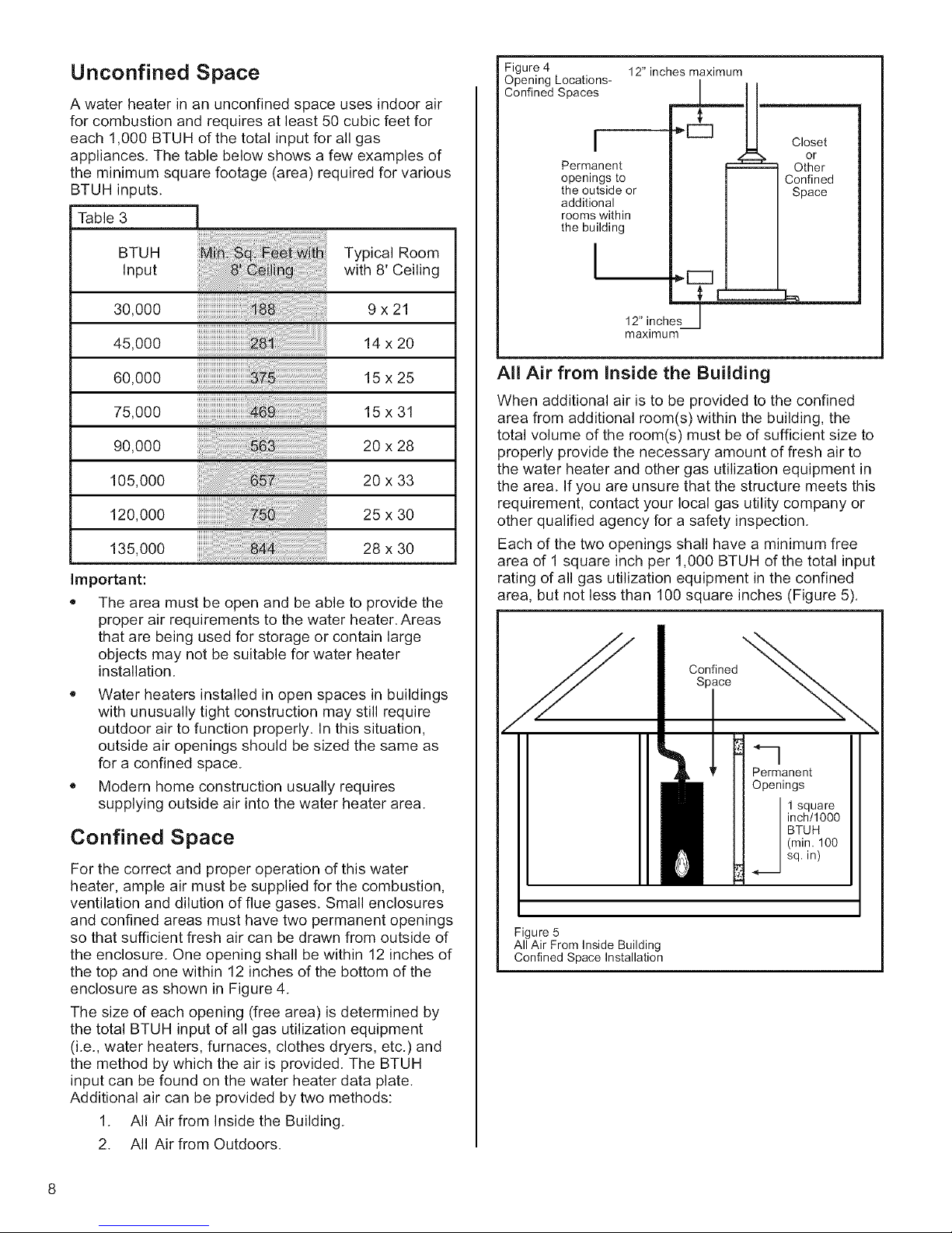
Table 3
BTUH Typical Room
Input with 8' Ceiling
Figure 4
Opening Locations-
Confined Spaces
I
Permanent
openings to
the outside or
additional
rooms within
the building
I
12" inches maximum
...1.._
Closet
or
-- Other
Confined
Space
30,000
45,000
60,000
75,000
90,000
105,000
120,000
135,000
9x21
14x20
15x25
15x31
20 x 28
20 x 33
25x 30
28 x 30
Important:
,, The area must be open and be able to provide the
proper air requirements to the water heater. Areas
that are being used for storage or contain large
objects may not be suitable for water heater
installation.
,, Water heaters installed in open spaces in buildings
with unusually tight construction may still require
outdoor air to function properly. In this situation,
outside air openings should be sized the same as
for a confined space.
• Modern home construction usually requires
supplying outside air into the water heater area.
Confined Space
For the correct and proper operation of this water
heater, ample air must be supplied for the combustion,
ventilation and dilution of flue gases. Small enclosures
and confined areas must have two permanent openings
so that sufficient fresh air can be drawn from outside of
the enclosure. One opening shall be within 12 inches of
the top and one within 12 inches of the bottom of the
enclosure as shown in Figure 4.
The size of each opening (free area) is determined by
the total BTUH input of all gas utilization equipment
(i.e., water heaters, furnaces, clothes dryers, etc.) and
the method by which the air is provided. The BTUH
input can be found on the water heater data plate.
Additional air can be provided by two methods:
1. All Air from Inside the Building.
2. All Air from Outdoors.
12" inch
maximum
All Air from Inside the Building
When additional air is to be provided to the confined
area from additional room(s) within the building, the
total volume of the room(s) must be of sufficient size to
properly provide the necessary amount of fresh air to
the water heater and other gas utilization equipment in
the area. If you are unsure that the structure meets this
requirement, contact your local gas utility company or
other qualified agency for a safety inspection.
Each of the two openings shall have a minimum free
area of 1 square inch per 1,000 BTUH of the total input
rating of all gas utilization equipment in the confined
area, but not less than 100 square inches (Figure 5).
Confined
Space
Permanent
Openings
inch/1000
BTUH
(min, 100
+_.....1 square
sq. in)
Figure 5
All Air From Inside Building
Confined Space Installation
All Air from Outdoors
Outdoor fresh air can be provided to a confined area
either directly or by the use of vertical and horizontal
ducts. The fresh air can be taken from the outdoors or
from crawl or attic spaces that freely communicate with
the outdoors. Attic or crawl spaces cannot be closed
and must be properly ventilated to the outside.
Ductwork must be of the same cross-sectional area as
the free area of the opening to which they connect. The
minimum dimension of rectangular air ducts cannot be
less than 3 inches.
The size of each of the two openings is determined by
the method in which the air is to be provided. Refer to
Table 4 to calculate the minimum free area for each
opening. Figures 6, 7, and 8 are typical examples of
each method.
Louvers and Grilles
In calculating free area for ventilation and combustion
air supply openings, consideration must be given to the
blocking effect of protection louvers, grilles, and
screens. These devices can reduce airflow, which in
turn may require larger openings to achieve the
required minimum free area. Screens must not be
smaller than 1/4-inch mesh. If the free area through a
particular design of louver or grille is known, it should
be used in calculating the specified free area of the
opening. If the design and free area are not known, it
can be assumed that most wood louvers will allow
20 - 25% of free area while metal louvers and grilles will
allow 60 - 75% of free area.
Louvers and grilles must be locked open or
interconnected with the equipment so that they are
opened automatically during equipment operation.
Keep louvers and grilles clean and free of debris or
other obstructions.
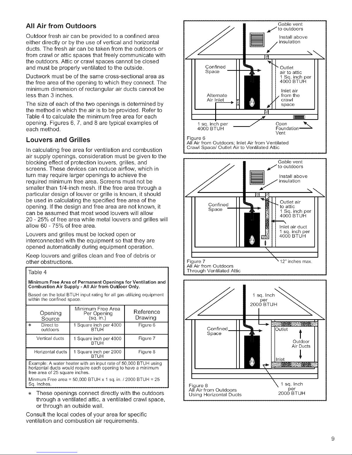
Table 4
Gable vent
to outdoors
Install above
insulation
Confined " Outlet
Space -- air to attic
Alternate _ from the
Air Inlet.. / crawl
/€_ space
F
1 sq. inch per Open
4000 BTUH Foundation '_
Figure 6
All Air from Outdoors; Inlet Air from Ventilated
Crawl Space/Outlet Air to Ventilated Attic
[_S nstall above
Confined
Space
i _! Outletair
Vent
Gable vent
to outdoors
insulation
b to attic
4000 BTUH
\
\
Figure 7
All Air from Outdoors
Through Ventilated Attic
\ 12" inches max.
1 Sq. inch per
4000 BTUH
Inlet air
1 Sq. inch per
4000 BTUH
Inlet air duct
1 sq. inch per
-,-.,,,
Minimum Free Area of Permanent Openings for Ventilation and
Combustion Air Supply - All Air from Ou_oor Only.
Based on the total BTUH input rating for all gas utilizing equipment
within the confined space.
Minimum Free Area
Opening Per Opening Reference
Source (sq. in.) Drawing
Direct to 1 Square inch per 4000 Figure 6
outdoors BTUH
Vertical ducts 1 Square inch per 4000 Figure 7
Horizontal ducts 1 Square inch per 2000 Figure 8
Example: A water heater with an input rate of 50,000 BTUH using
horizontal ducts would require each opening to have a minimum
free area of 25 square inches.
Minmum Free area = 50,000 BTUH x 1 sq. in. / 2000 BTUH = 25
Sq. Inches.
BTUH
BTUH
These openings connect directly with the outdoors
through a ventilated attic, a ventilated crawl space,
or through an outside wall.
Consult the local codes of your area for specific
ventilation and combustion air requirements.
1 Sqe,rnCh_..
2000 BTU H "___
Confined
Space
Figure 8 1 sq. Inch
All Air from Outdoors per
Using Horizontal Ducts 2000 BTUH
Outlet t
Outdoor
Air Ducts
Inlet _'
 Loading...