

Page 1

SERVICE MANUAL
for the
FREESTANDING
SELF-CLEAN
GAS RANGE
LIT 4321891Printed in U.S.A.July, 1996
Page 2

THIS MANUAL CONTAINS INFORMATION
NECESSARY FOR INSTALLING AND SERVICING
THE FOLLOWING FREESTANDING SELF-CLEAN
GAS RANGES, MODELS:
WHIRLPOOL
SF350BEE W SF375PEE Q/Z
SF360BEE W/N SF385PEE W/N
SF372BEE W/N SF385PEE Q/Z
SF372BEE Q/Z SF395LEE Q/Z/B
SF375PEE W/N
ROPER
FGS335E W/N
FGS335E Q
ESTATE
TGS325E W
THE MANUAL IS DESIGNED TO BE USED
ONLY BY QUALIFIED SERVICE PERSONNEL.
THE SERVICE INFORMATION IS ORGANIZED
TO HELP YOU EASILY FIND WHAT YOU NEED.
CHECK YOUR LOCAL BUILDING CODE FOR THE
PROPER MODE OF INSTALLATION. IN THE
ABSENCE OF LOCAL CODES, THIS UNIT
SHOULD BE INSTALLED IN ACCORDANCE WITH
THE
NATIONAL STANDARD, NATIONAL FUEL
GAS CODE ANSI Z223.1 — LATEST EDITION*.
* National Gas Association
1515 Wilson Boulevard
Arlington, Virginia 22209
- ii -
Page 3
Cooking Products Service Manual
Original July, 1996 4321891
© 1996 Whirlpool Corporation
Page iii
Table of Contents
Page
Important Safety Information ........................................................................................................ v
Installation Highlights .......................................................................................................................1-1
Range Dimensions ......................................................................................................................1-1
Cabinet Dimensions ....................................................................................................................1-2
Tools & Material You Will Need ................................................................................................1-3
Electrical Supply Requirements ................................................................................................1-4
Gas Supply Requirements .........................................................................................................1-6
Installing The Range ...................................................................................................................1-7
Converting The Pressure Regulator & Maintop Burners For L.P. Gas............................. 1-10
Checking The Maintop Burner Operation ............................................................................. 1-13
Adjusting The Air Shutters .................................................................................................. 1-14
Converting The Oven Burners For L.P. Gas ........................................................................ 1-15
Checking the Oven Burner Operation ................................................................................... 1-16
Removing/Reinstalling The Oven Door ................................................................................. 1-20
Theory Of Operation .........................................................................................................................2-1
Component Access ...........................................................................................................................3-1
Removing The Maintop—Sealed Burner Models ....................................................................3-2
Removing The Maintop—Conventional Burner Models ......................................................... 3-4
Removing A Sealed Burner & A Venturi ..................................................................................3-5
Removing A Conventional Burner ............................................................................................. 3-6
Removing A Spark Ignitor Switch & Gas Valve ......................................................................3-7
Removing The Ignitor Module & A Burner Ignitor—Sealed Burner Models ........................ 3-8
Removing The Ignitor Module & A Burner Ignitor—Conventional Burner Models .......... 3-10
Removing The Oven Door Latch & Actuator Rod—Sealed Burner Models ..................... 3-12
Removing The Oven Door Latch & Actuator Rod—Conventional Burner Models .......... 3-14
Removing The Latch Sensing Switches, The Door Latch Solenoid,
& The Mechanical Latch....................................................................................................... 3-16
Removing The Upper Console................................................................................................ 3-18
Removing The Electronic Oven Control ................................................................................ 3-20
Removing An Oven Light Switch ............................................................................................ 3-21
Removing The Gas Safety Valve & Pressure Regulator .................................................... 3-22
Removing The Bake Burner & Ignitor .................................................................................... 3-23
Removing The Broil Burner & Ignitor..................................................................................... 3-24
Removing The Oven Temperature Sensor ........................................................................... 3-25
Removing A Side Panel ........................................................................................................... 3-26
Removing An Oven Light Socket ........................................................................................... 3-28
Removing The Oven Door Gasket ......................................................................................... 3-29
Removing The Oven Door Handle, Top Trim, & Outer Door Glass .................................. 3-30
Removing A Hinge Assembly.................................................................................................. 3-31
Removing The Inner Door Glass ............................................................................................ 3-33
Removing The Storage Drawer Glides .................................................................................. 3-34
- iii -
Page 4

Page
Component Description & Testing .................................................................................................. 4-1
Troubleshooting ...........................................................................................................................4-1
Troubleshooting Chart ......................................................................................................... 4-11
Oven Temperature Calibration ............................................................................................... 4-13
Error Codes ............................................................................................................................... 4-13
Tech Tips ............................................................................................................................................5-1
Wiring Diagram 1 ......................................................................................................................... 5-1
Wiring Diagram 2 ......................................................................................................................... 5-2
Strip Circuits.................................................................................................................................5-3
Specifications ...............................................................................................................................5-5
Model And Serial Number Explanation ................................................................................. 5-20
Warranty .................................................................................................................................... 5-21
- iv -
Page 5
IMPORTANT SAFETY INFORMATION
WARNING
This service manual is intended for factory-service
technicians only. We recommend that customers
DO NOT service their own units, because of the
complexity and risk of high-voltage electrical shock.
The following information is used throughout this
manual, and should be read carefully.
NOTE
Helpful information that explains a more complicated step, prior to carrying it out .
Cooking Products Service Manual
Original July, 1996 4321891
© 1996 Whirlpool Corporation
Fire Hazard
Do not obstruct the flow of combustion and
ventilation air.
Electrical Shock Hazard
It is the customer’s responsibility to:
• Contact a qualified electrical installer.
• Assure that electrical installation is adequate
and in conformance with the National Electrical Code, ANSI/NFPA 70—latest edition*,
and all local codes and ordinances.
Page v
CAUTION
Information that will help you avoid actions
that could cause product damage (scratches,
dents, etc.) and damage to personal property.
WARNING
Information that alerts you to potentially dangerous conditions. These conditions can
cause serious personal injury (burns, fire and
electrical shock, etc.) if the suggested procedures are not observed.
WHIRLPOOL CORPORATION ASSUMES NO RE-
SPONSIBILITY FOR ANY REPAIRS MADE ON
OUR PRODUCTS BY ANYONE OTHER THAN
AUTHORIZED WHIRLPOOLSM SERVICE TECH-
NICIANS.
Failure to do so could result in fire, electrical
shock, or other personal injury.
Take special care when drilling holes into the
wall for venting or electrical wiring. Electrical
wires may be concealed behind the wall covering.
Failure to do so could result in fire, electrical
shock, or other personal injury.
* National Fire Protection Association
Batterymarch Park
Quincy, Massachusetts 02269
- v -
Page 6
WARNING
To reduce the risk of fire, electrical shock,
injury to persons, or damage when using
the range, follow these basic precautions:
1. Read all instructions before using the
range.
2. Install or locate the range only in accordance with the provided installation instructions. It is recommended that the
range be installed by a qualified installer.
The range must be properly connected to
the correct gas supply and checked for
leaks. The range must also be properly
connected to a grounded electrical supply.
3. Gas fuels and combustion can result in
potential exposure to chemicals known to
cause cancer or reproductive harm. For
example, benzene is a chemical which is
a part of the gas supplied to the range. It
is consumed in the flame during combustion. However, exposure to a small amount
of benzene is possible if a gas leak occurs. Formaldehyde and soot are by-products of incomplete combustion. Properly
adjusted burners with a bluish rather than
a yellow flame will minimize incomplete
combustion.
4. Do not use the range for heating the room.
Persons could be burned or injured, or a
fire could start.
5. Do not leave children alone or unattended
in area where the range is in use. They
should never be allowed to sit or stand on
any part of the range. They could be
burned or injured.
6. Do not wear loose or hanging garments
when using the range. Clothing could ignite if it touches a surface burner and you
could be burned.
7. Do not repair or replace any part of the
range unless specifically recommended
in this manual. All other servicing should
be referred to a qualified technician.
8. Do not operate the range if it is not working properly, or if it has been damaged or
dropped.
9. Know where your main gas shut off valve
is located.
10. Clean your range regularly. See “Care
and Cleaning” instructions that are included with the range.
11. Use the range only for its intended use as
described in this manual.
12. Do not store flammable materials on or
near the range. They could explode or
burn.
13. Do not use water on grease fires. Never
pick up a flaming pan. Smother flaming
pan on range by covering with a wellfitting lid, cookie sheet or flat tray. Flaming grease outside of pan can be extinguished with baking soda, or if available,
a multipurpose dry chemical or foam-type
extinguisher.
14. Use only dry potholders. Moist or damp
potholders on hot surfaces may result in
burns from steam. Do not let potholder
touch an open flame. Do not use a towel
or bulky cloth for a potholder. It could
catch on fire.
15. Make sure the utensils you use are large
enough to contain food and avoid boilovers
and spillovers. Heavy splattering or
spillovers left on a range can ignite and
burn you. Pan size is especially important
in deep fat frying.
16. Never leave burners unattended at high
flame settings. A boilover could result
and cause smoking and greasy spillovers
that may ignite.
- vi -
Page 7
Cooking Products Service Manual
Original July, 1996 4321891
© 1996 Whirlpool Corporation
Page vii
17. Grease is flammable and should be
handled carefully. Let fat cool before attempting to handle it. Do not allow grease
to collect around range or in vents. Wipe
spillovers immediately.
18. Check to be sure glass cooking utensils
are safe for use on the range. Only certain
types of glass, glass-ceramic, earthenware or other glazed utensils are suitable
for ranges. Other types may break due to
the sudden change in temperature.
19. Turn pan handles inward, but not over
other burners. This will help reduce the
chance of burns, igniting of flammable
materials, and spills due to bumping the
pan.
20. Do not heat unopened containers. They
could explode. The hot contents could
cause burns and container particles could
cause injury.
21. Do not use decorative covers or trivets
over the surface burners.
22. Do not store things children might want
above the range. Children could be burned
or injured while climbing on range.
23. Do not touch hot burners or areas near
burners. Areas near burners become hot
enough to cause burns. During use, do
not touch or let clothing or other flammable materials contact burners, or areas near burners.
24. Do not block the ventilation.
25. Never use a match or other flame to look
for a gas leak. Explosion and injury could
result.
26. Make sure the burners are off when you
are finished, and when you are not watching.
27. Be sure all range parts are cool before
cleaning.
- vii -
Page 8

— NOTES —
- viii -
Page 9

Cooking Products Service Manual
Original July, 1996 4321891
© 1996 Whirlpool Corporation
INSTALLATION HIGHLIGHTS
RANGE DIMENSIONS
Page 1-1
GENERAL
Proper installation is your responsibility. A qualified technician must install this range. Make sure
you have everything necessary for correct installation. It is the responsibility of the installer to comply
with the installation clearances specified on the
oven model/serial rating plate. This plate is located
on the frame behind the storage door panel. IM-
PORTANT: Be sure to observe all governing codes
and ordinances. In the absence of local codes,
installation must conform with American National
Standard, National Fuel Gas Code ANSI Z223.1 —
latest edition*.
* American Gas Association
1515 Wilson Boulevard
Arlington, Virginia 22209
The dimensions of the range are shown below.
Check the location where the range will be installed. The location should be away from strong
draft areas, such as windows, doors, and strong
heating vents or fans. The range should be located
for convenient use in the kitchen.
ALL OPENINGS IN THE WALL OR FLOOR ARE
TO BE SEALED AFTER THE RANGE IS INSTALLED.
MOBILE HOME INSTALLATION
The installation of this range must conform with the
Manufactured Home Construction and Safety Standard, Title 24 CFR, Part 3280 (formerly the Federal
Standard for Mobile Home Construction and Safety,
Title 24, HUD, Part 280), or when such standard is
not applicable, the Standard for Manufactured
Home Installations, ANSI A225.1/NFPA 510A, or
with local codes.
When this range is installed in a mobile home, it
must be secured to the floor during transit. Any
method of securing the range is adequate as long
as it conforms to the standards listed above.
Copies of standards listed may be obtained from:
National Fire Protection Association
Batterymarch Park
Quincy, Massachusetts 02269
27-1/8" depth
with handle
24-13/16
46-7/8
"
overall
height
36
"
cooktop
height
"
29-7/8" width
1-1
Page 10
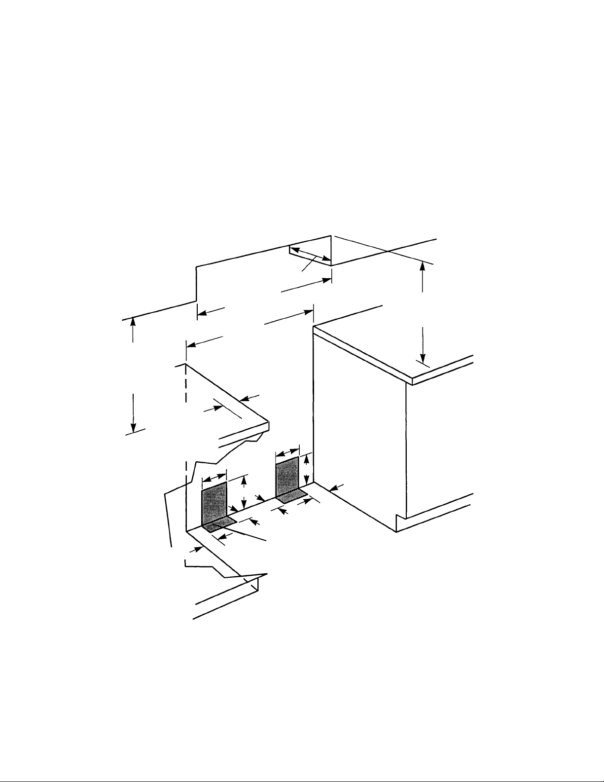
CABINET DIMENSIONS
Use only the cabinet opening dimensions that are
shown below. The dimensions shown are for minimum clearances.
A grounded electrical outlet is required (see page
1-4).
A proper gas supply connection must be available
(see page 1-6).
max. upper
cabinet depth
"
min.
30
cabinet opening width
1
/8" min.
30-
opening width
18
"
min.
clearance upper
cabinet to
countertop
2" minimum
countertop
space to side
wall or other
combustible
material
8
Contact a qualified
floor covering installer
to check that the floor
covering can withstand
at least 90˚F above
room temperature.
Use an insulated
pad, or 1/4" plywood
under the range if
installing the range
over carpeting.
The Anti-Tip bracket MUST be
installed. (See page 1-7 for
details.)
4-1/2
"
"
17
"
2
"
This shaded area shown in the illustration is the recommended area for
installation of rigid gas pipe.
Flexible gas pipe and an electrical
outlet are recommended in either
shaded area.
Do not pinch the power cord between the range and the wall when
you push the range into its mounting location.
Clearance Note:
A clearance of 30" minimum is
required when the bottom of a wood or metal
1
cabinet is protected by not less than
/4" of flameretardant millboard covered with not less than #28
MSG sheet steel, 0.015
stainless steel, 0.024
"
"
aluminum, or 0.020" copper. A minimum clearance
"
between the top of the cooking platform and
of 36
the bottom of an unprotected wood or metal cabinet is required.
13
"
Refer to
“Clearance
Note” above.
Do not seal the range to
the side cabinets.
If the cabinet depth
is greater than 24", the
oven frame must extend
beyond the cabinet
8
"
17
"
4-1/2
"
2
"
front by 1/2" minimum.
1-2
Page 11
Cooking Products Service Manual
Original July, 1996 4321891
© 1996 Whirlpool Corporation
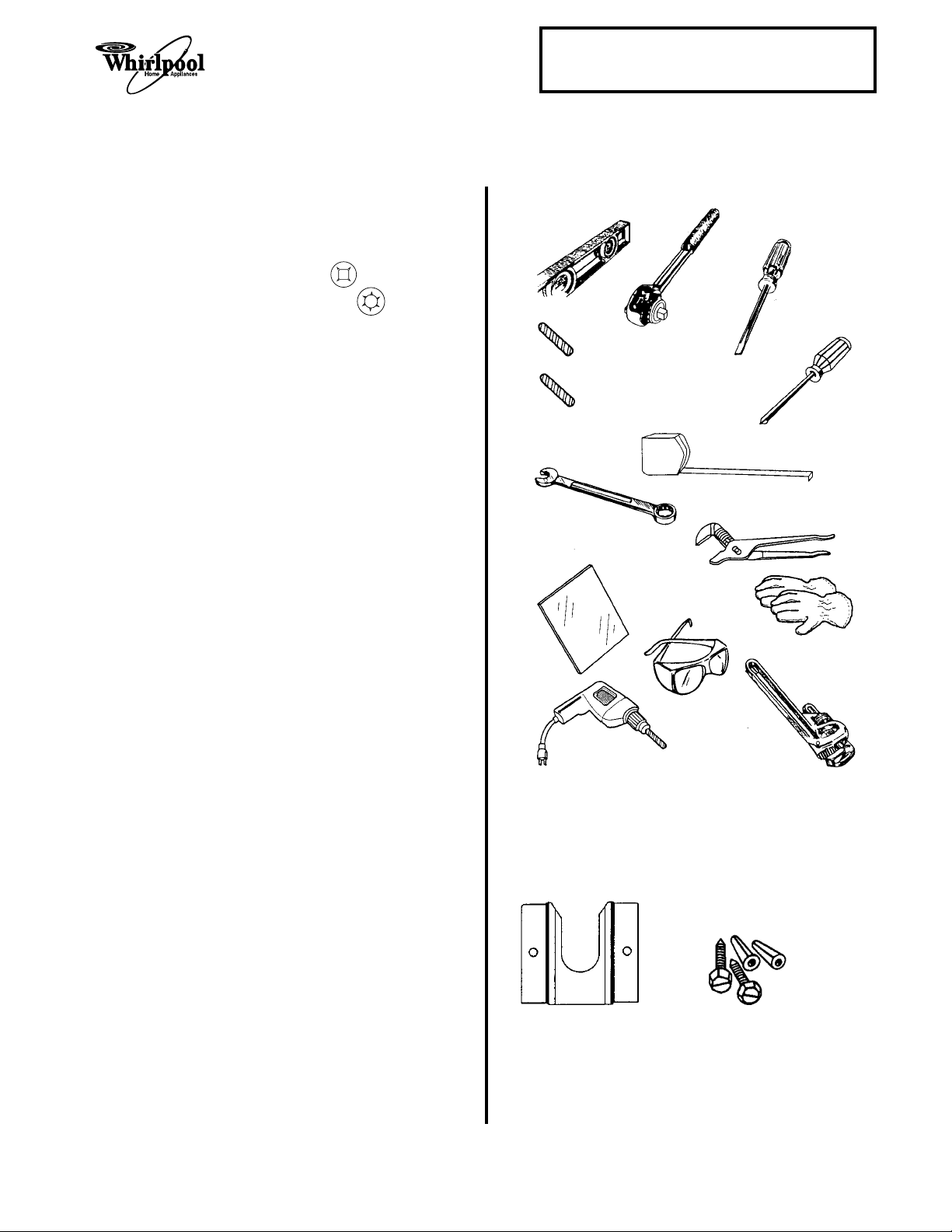
TOOLS & MATERIAL YOU WILL NEED
Page 1-3
TOOLS
Standard (flat-bladed) screwdriver
Phillips screwdriver
Robertson (S2) screwdriver
Torx (T10 & T20) screwdrivers
Spirit level
Pipe wrench
Channel lock pliers
Measuring tape
3
/8" ratchet drive
Hand or electric drill
1
/8" wood drill bit or 3/16" carbide-tipped
masonry drill bit
15
/16" , 1/2", & 3/8" combination wrench
Mirror
Safety glasses
Gloves
ADDITIONAL MATERIAL
ILLUSTRATIONS
spirit level
3/8" ratchet
drive
wood floor:
1/8" drill bit
concrete/ceramic floors:
3/16" carbide-tipped
masonry drill bit
15/16", 1/2" and
3/8" combination
wrench
mirror
flat-blade
screwdriver
Phillips
screwdriver
tape measure
or ruler
channel lock
pliers
gloves
Gas line shutoff valve
1
/2" male pipe thread for connection to pressure
regulator
L.P. gas-resistant pipe-joint compound
A.G.A. design-certified flexible metal connector
(4 to 5 feet), or rigid gas supply line
1
Insulated pad or
/4" plywood, if range is installed
over carpeting
PARTS SUPPLIED
1 Anti-tip bracket
2 Plastic anchors
2 Screws (#10 x 1-
ness of the flooring may require longer
screws. These are available at your local
hardware store.
1
/2" ) NOTE: The thick-
hand or
electric drill
ANTI-TIP BRACKET
safety glasses
pipe wrench
#10 X 1-1/2" SCREWS
PLASTIC
ANCHORS
1-3
Page 12
ELECTRICAL SUPPLY REQUIREMENTS
WARNING
Electrical Shock Hazard
An electrical ground is required on this appliance.
If a cold water pipe is interrupted by plastic,
nonmetallic gaskets, or other insulating materials, do not use for grounding.
Do not ground to a gas pipe.
Do not change the power supply cord plug. If the
plug will not fit the outlet, have a proper outlet
installed by a qualified electrician.
Do not use a fuse in the neutral or grounding
circuit. It could result in an electrical shock.
Do not use an extension cord with this range.
Check with a qualified electrician if you are in
doubt as to whether the appliance is properly
grounded.
Failure to follow these instructions could result in
serious injury or death.
The following information applies to the gas range
wiring:
• A 3-wire, single phase, 120-volt, 60 Hz, AC-
only electrical supply is required on a separate 10-ampere circuit, fused on both sides of
the line. A time-delay fuse, or circuit breaker,
is recommended. The fuse must be sized as
per local codes in accordance with the electrical rating of the appliance specified on the
model/serial rating plate, which is located on
the frame behind the storage door panel.
• The gas range must be connected with cop-
per wire only.
• Wire sizes and connections must conform to
the requirements of the National Electrical
Code, ANSI/NFPA 70—latest edition*, and all
local codes and ordinances. Wire sizes and
connections must conform with the rating of
the appliance. Copies of the standards listed
above may be obtained from:
National Fire Protection Association
*
Batterymarch Park
Quincy, Massachusetts 02269
Equipment & Property Damage
Use a separate power line for this gas range,
and make sure that you connect it to the proper
voltage source. Failure to do so could result in
improper operation, equipment, or property damage.
GENERAL
If codes permit, and a separate grounding wire is
used, it is recommended that a qualified electrician
determine that the grounding path is adequate.
• The gas range should be connected directly
to the fused disconnect (or circuit breaker)
through flexible, armored, or nonmetallic
sheathed, copper cable. The flexible, armored
cable that extends from the appliance should
be connected directly to the junction box.
• Locate the junction box to allow as much slack
as possible between the junction box and the
appliance so that the appliance can be moved
if servicing is ever necessary. Do not cut the
conduit.
1
• A U.L.-listed,
provided at the junction box.
• A wiring diagram is located in the “Tech Tips”
(Section 5) of this manual.
/2" conduit connector must be
1-4
Page 13
WARNING
Personal Injury/Fire Hazard
Do not, under any circumstances, cut or remove the grounding prong from the range cord.
Failure to provide proper polarization may cause
shock and fire hazard.
ELECTRONIC IGNITION SYSTEM
Cooking Products Service Manual
Original July, 1996 4321891
© 1996 Whirlpool Corporation
Page 1-5
Once you are sure that the plug is polarized properly, perform the next step.
2. Connect the power cord plug on the gas range
to a 120-volt AC receptacle that is on a separately fused line.
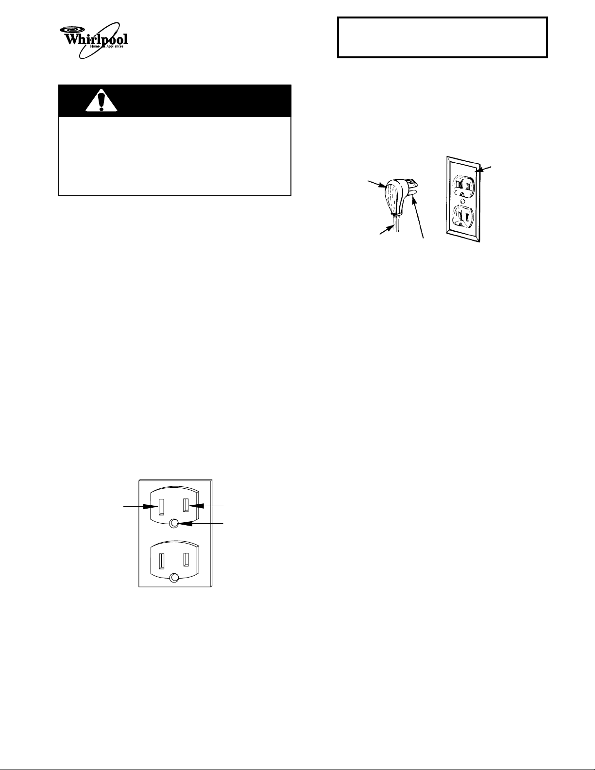
3-PRONG
GROUNDING-
3-PRONG
GROUNDING PLUG
TYPE WALL
RECEPTACLE
When connecting an appliance that has an electronic ignition system to a 120-volt AC receptacle, it
is very important that the receptacle wiring is correctly polarized and properly grounded. If the plug is
not polarized properly, the ignitor module will not
operate correctly.
1. The 120-volt AC receptacle should use 3wires, and be polarized with two plug slots
and a round grounding pin. Proper wiring for
this type of receptacle is as follows:
a) The white wire is connected to the neutral
side of the plug.
b) The black wire is connected to the hot
(120-volt ac) side of the plug.
c) The green, or bare wire is connected to
the round grounding pin of the plug.
3-WIRE
AC RECEPTACLE
WHITE
BLACK
POWER SUPPLY
CORD
GROUNDING PRONG
GREEN
1-5
Page 14
GAS SUPPLY REQUIREMENTS
WARNING
Fire Hazard
The gas appliance must be connected to a
regulated gas supply.
Do not use an open flame to test for gas leaks
from gas connections.
New A.G.A.-designed and certified flexible gas
line should be used, when codes permit.
Do not store or use gasoline, or any other
flammable vapors and liquids, in the vicinity of
this, or any other appliance.
If you smell gas:
• Do not light any appliance.
• Do not operate any electrical switches.
• Do not use the telephone.
• Call the gas supplier immediately from a
neighbor’s telephone, and follow the gas
supplier’s instructions carefully.
• If you cannot reach the gas supplier, call the
fire department.
Failure to follow these instructions could result in
fire, explosion, or other personal injury.
This range is factory set for use with natural gas. It
is designed-certified by the American Gas Association (A.G.A.) for natural or L.P. gases with the
appropriate conversion. The model/serial rating
plate has information on the type of gas that can be
used. If the type of gas listed does not agree with
the type of gas available, check with the local gas
supplier. Conversion must be done by a qualified
service technician.
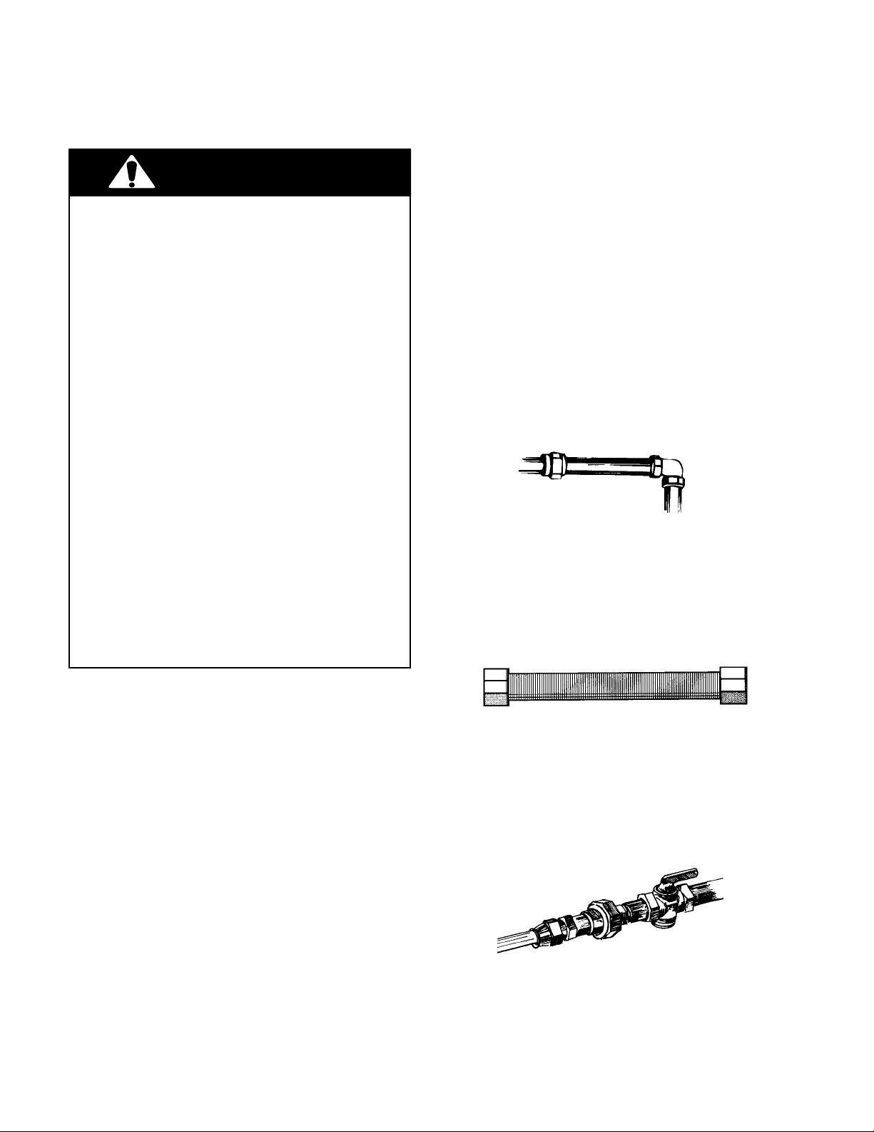
3
A rigid,
both natural and L.P. gas at the gas range installation location. Long lengths of smaller size pipe may
result in an insufficient supply of gas to the range.
Pipe-joint compounds, made for use with natural
and L.P. gas, must be used.
If local codes and ordinances permit, new A.G.A.approved, flexible metal tubing can be used for
connecting the appliance to the gas supply line. Do
not kink or damage the flexible tubing when moving
the appliance. A
connecting to the female pipe threads of the pressure-regulator.
/4" gas supply pipe, must be provided for
3
/4" male pipe thread is needed for
GENERAL
This installation must conform with local codes and
ordinances. In the absence of local codes, installation must conform with the American National
Standard, National Fuel Gas Code ANSI Z223.1—
latest edition.*
Copies of the standards listed above may be obtained from:
* American Gas Association
1515 Wilson Boulevard
Arlington, Virginia 22209
Input ratings shown on the model/serial rating plate
(located on the frame behind the storage door
panel) are for elevations up to 2,000 feet. For
elevations above 2,000 feet, contact the local service company.
The supply line must be equipped with an approved shutoff valve. This valve should be located
in the same room as the appliance, and should be
in a location that allows easy access to turn the gas
supply on and off. Do not block the access to the
shutoff valve. Never reuse an old connector
when installing a new range.
1-6
Page 15
INSTALLING THE RANGE
WARNING
Electrical Shock Hazard
Take special care when drilling holes in the
floor or wall. Electrical wires may be behind the
wall or floor covering and could cause an
electrical shock if you touch them.
Locate the electrical circuits that could be affected by the installation of the anti-tip bracket
and turn off power to these circuits.
Cooking Products Service Manual
Original July, 1996 4321891
© 1996 Whirlpool Corporation
5. Remove the cardboard shipping base from
under the range.
6. Remove the storage drawer from the range.
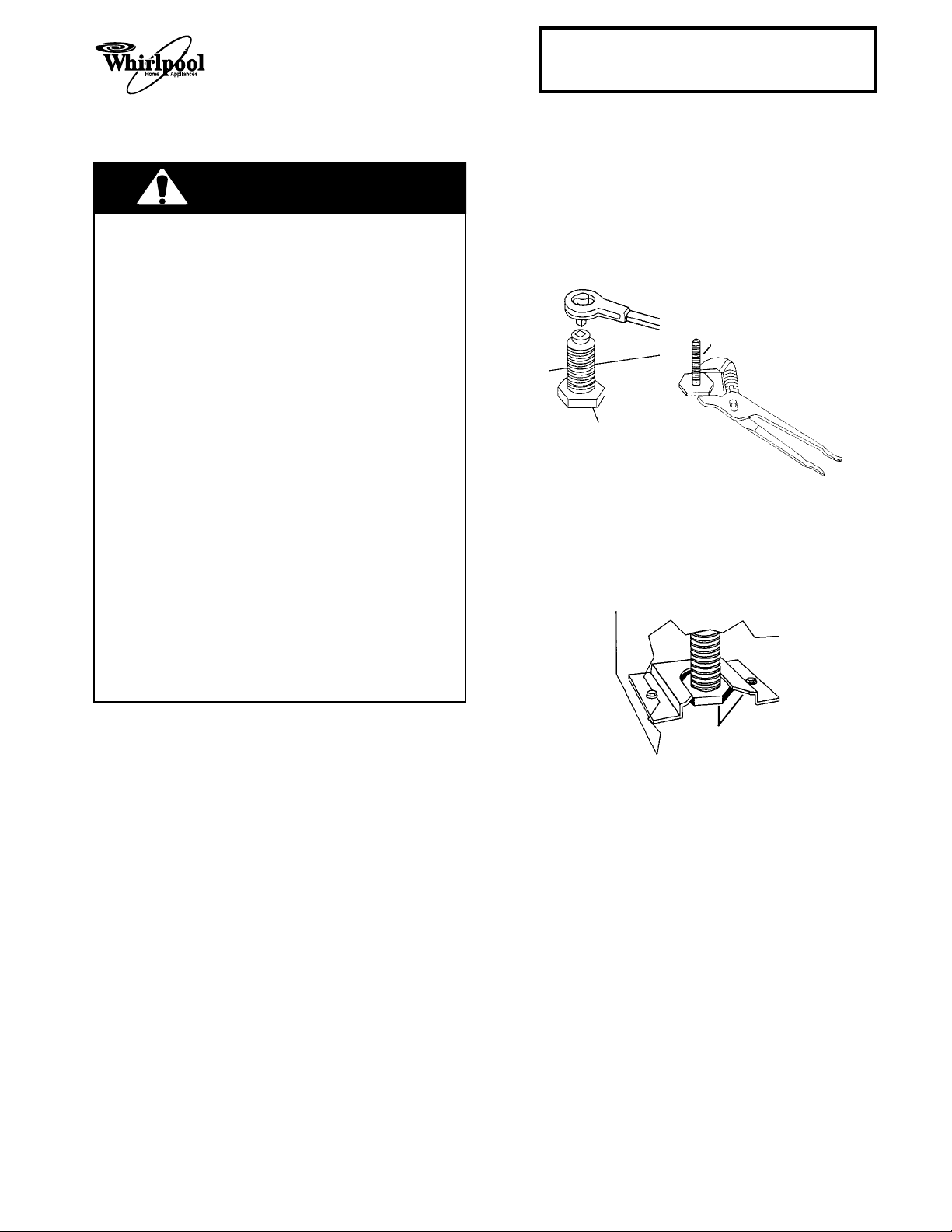
3
7. Using a
ing legs
/8" drive ratchet, lower the rear level-
1
/2 -turn.
front leveling leg
Page 1-7
Personal Injury Hazard
To reduce the risk of tipping of the range, the
range must be secured by a properly installed
floor-mounted anti-tip bracket, supplied with
the range.
If range is moved to a new location, the anti-tip
bracket must be reinstalled in the new location.
Because of the weight and size of this range,
two or more people are required to move it.
Do not use the handle for lifting.
Failure to follow these instructions could result
in injury.
INSTALLING THE ANTI-TIP
BRACKET
1. Use safety glasses and gloves to install the
range.
2. Remove the oven racks and parts package
from inside the oven. Also remove all shipping
materials, tape, and protective film from the
range.
3. Slide a cardboard shipping base under the
range to prevent damage to the floor covering.
4. Use the anti-tip bracket template/instruction
sheet, and install the anti-tip bracket. The
anti-tip bracket must be anchored securely to
the sub floor. Depending on the thickness of
the flooring, longer screws may be needed to
anchor the bracket to the sub floor.
rear leveling leg
8. Use channel lock pliers and lower the front
leveling legs
9. Carefully move the range to its final operating
location. Make sure that the rear leveling leg
is engaged in the anti-tip bracket .
10. If you are installing the range in a mobile
home, secure the range to the floor. Use a
method that complies with the standards in
the “Mobile Home Installation” instructions on
page 1-1.
11. Place the racks in the oven, then place a level
on a rack, and check to make sure that the
range is level. Readjust the legs, as necessary. NOTE: For proper baking conditions,
the range must be level.
1
/2 -turn.
slide leg in anti-tip bracket
1-7
Page 16
WARNING
Fire Hazard
pressure regulator
When you make gas line connections, especially to the pressure regulator, do not make the
connections too tight. If you do, you may crack
the regulator (or pipe) and cause a gas leak,
which could result in a possible fire, or explosion.
INSTALLING THE GAS LINE
The following procedure is for a typical gas line
installation and its associated components to the
gas range. Use pipe-joint compound that is made
for use with natural and L.P. gas to seal all of the
connections. Tighten all of the connections with an
adjustable (pipe) wrench.
1. Turn all of the range knobs to OFF.
2. Remove the storage drawer so you can access the regulator.
3. Remove the plastic dust cap from the inlet of
the pressure regulator.
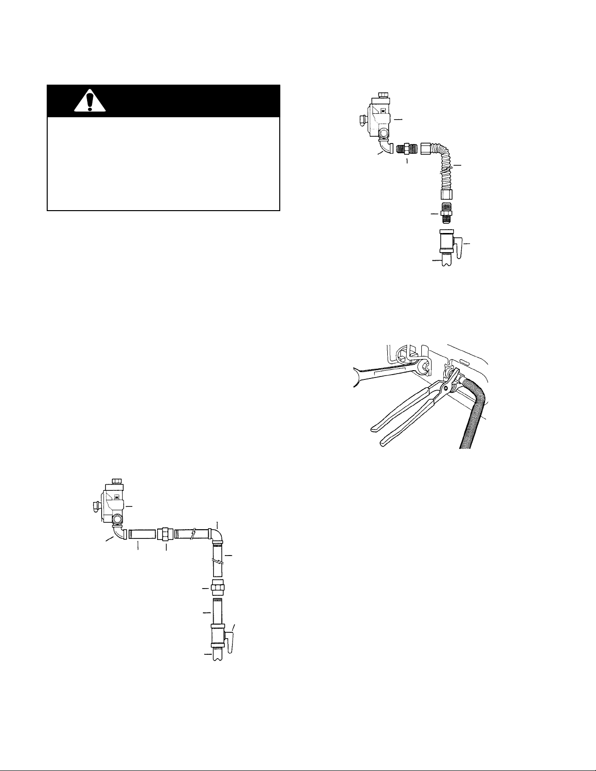
4. Assemble the rigid or flexible gas line between the gas supply pipe and the pressure
regulator. Typical installations are shown in
the following two illustrations. Use pipe-joint
compound that is made for L.P. gas to seal the
connections.
90˚ elbow
adapter
adapter
1/2" to 3/4
gas pipe
A Typical Flexible Gas Line
flexible line
gas shutoff valve
"
5. Use a 15/16" combination wrench and channel
lock pliers and tighten all of the fittings securely.
6. Seal all of the openings in the floor or wall
around the range installation.
90˚ elbow
pressure regulator
90˚ elbow
nipple union iron pipe
union
nipple
1/2" to 3/4
gas pipe
A Typical Rigid Gas Line
gas shutoff
valve
"
1-8
Page 17
Cooking Products Service Manual
Original July, 1996 4321891
© 1996 Whirlpool Corporation
Page 1-9
CHECKING FOR LEAKS
WARNING
Fire Hazard
Turn off the main gas supply before you try to
stop a leak.
Be sure that all leaks are stopped before lighting
pilots or burners.
Do not use an open flame to test for gas leaks.
Failure to follow these instructions could result in
a possible fire, or explosion.
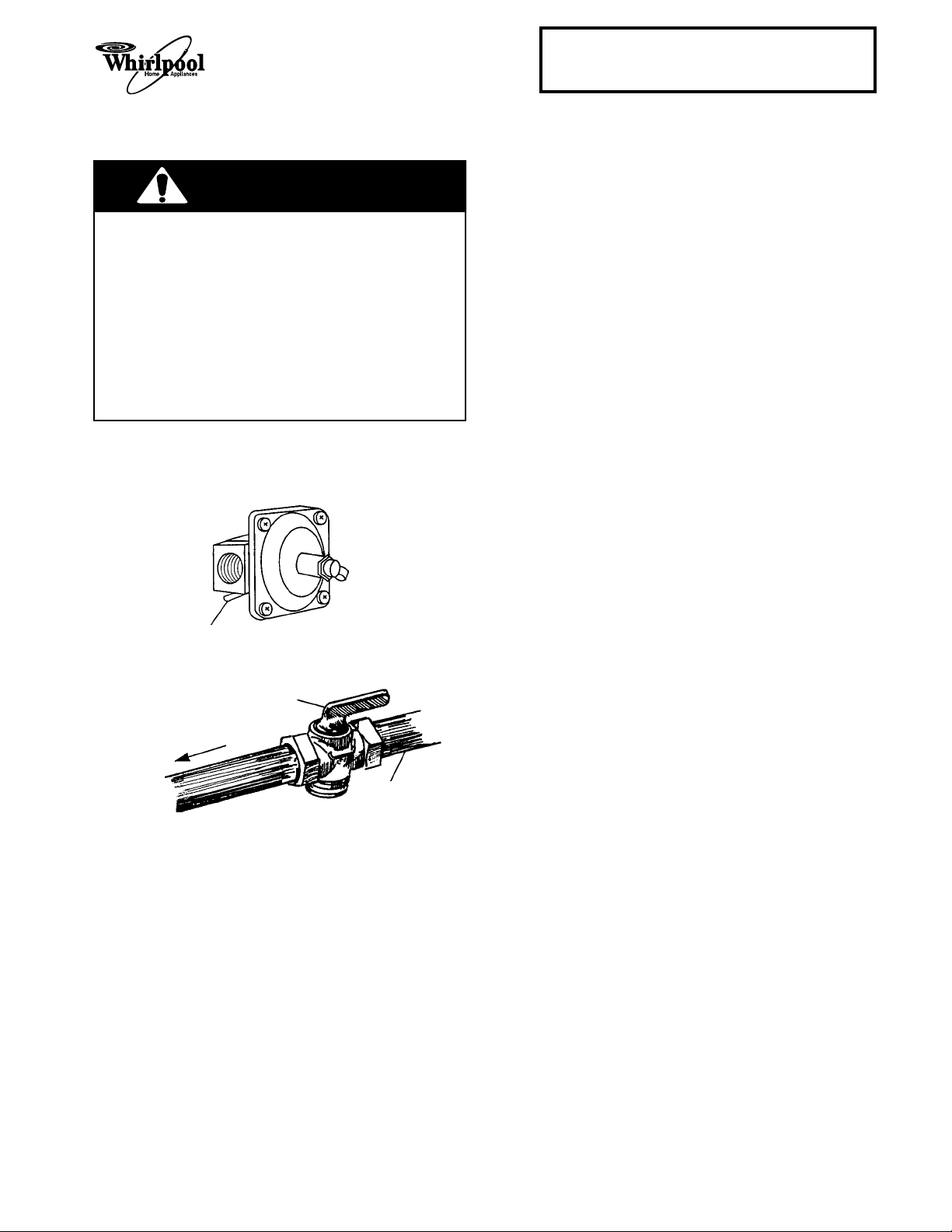
1. Make sure that no open flame is present, then
open the gas line shutoff valve and the regulator shutoff valve.
regulator shutoff valve
to “open” position
CHECKING THE PRESSURE
REGULATOR
The pressure regulator must be checked at a
"
minimum 1
The inlet pressure to the regulator should be set as
follows:
a) Set the minimum pressure using natural
b) Set the maximum pressure at 14".
For testing the line pressure above
pressure gauge:
a) Disconnect the appliance and its individual
For testing the line pressure @
a pressure gauge:
a) Close the gas supply shutoff valve to the
NOTE: If you are converting the range for L.P. gas,
proceed to the next page. If not, proceed to “Checking The Maintop Burner Operation” on page 1-13.
water column above the set pressure.
gas @ 5
and for L.P. gas @ 11
".
1
/2 psi with a
"
shutoff valve from the gas supply when the
1
pressures are greater than
/2 psi (3.5 kPa).
1
/2 psi or lower with
appliance when the pressures are equal to,
1
or less than
/2 psi (3.5 kPa).
open gas line
shutoff valve
to range
gas supply
2. Turn one of the burner gas valves on until the
air in the line is expelled and gas begins to
flow out the burner, then turn the valve off.
3. Use a brush and liquid detergent and check all
the connections for possible leaks. If bubbling
occurs around the joint, tighten the connection further until the bubbling just stops. Do
not overtighten the connection.
1-9
Page 18
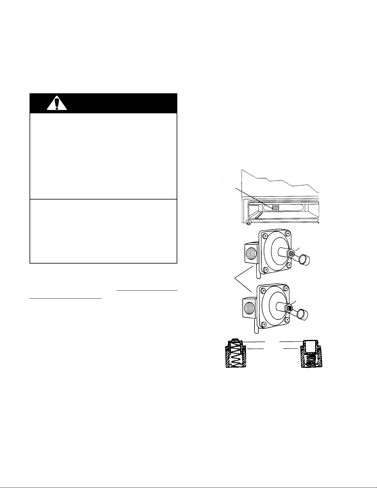
CONVERTING THE PRESSURE REGULATOR &
MAINTOP BURNERS FOR L.P. GAS
THE PRESSURE REGULATOR
WARNING
Personal Injury Hazard
Do not operate the burners of this range when
using L.P. (bottled) gas before converting the
pressure regulator, burner orifices, and oven
pilot adjustment screw (if applicable), for L.P.
gas usage.
Failure to follow these instructions could result
in high flames and toxic fumes, causing serious
injury.
Fire Hazard
Shut off the gas supply line valve.
Make all conversions before turning gas supply
valve back on.
Failure to follow these instructions could result
in explosion, fire, or other injury.
1. Remove the storage drawer from the range.
2. Remove the plastic cover from the pressure
regulator.
3. Use a wrench, and turn the cap marked “N” on
the front of the pressure regulator counterclockwise, and remove it. NOTE: Do not disturb the spring under the cap.
L.P.
4. Turn the cap over so that the letters
visible and reinstall it into the regulator.
5. Reinstall the plastic cover on the pressure
regulator.
Pressure Regulator
Natural Gas
are
Conversions to the pressure regulator and burner
orifices for L.P. gas usage must be done by a
qualified service technician.
regulator to convert it.
To convert the regulator from natural to L.P. gas,
use the following procedure:
Do not remove the
Pressure Regulator
Natural Gas
L.P. Gas
cap
washer
L.P. Gas
1-10
Page 19
Cooking Products Service Manual
LEFT VENTURI
RIGHT VENTURI
Original July, 1996 4321891
© 1996 Whirlpool Corporation
Page 1-11
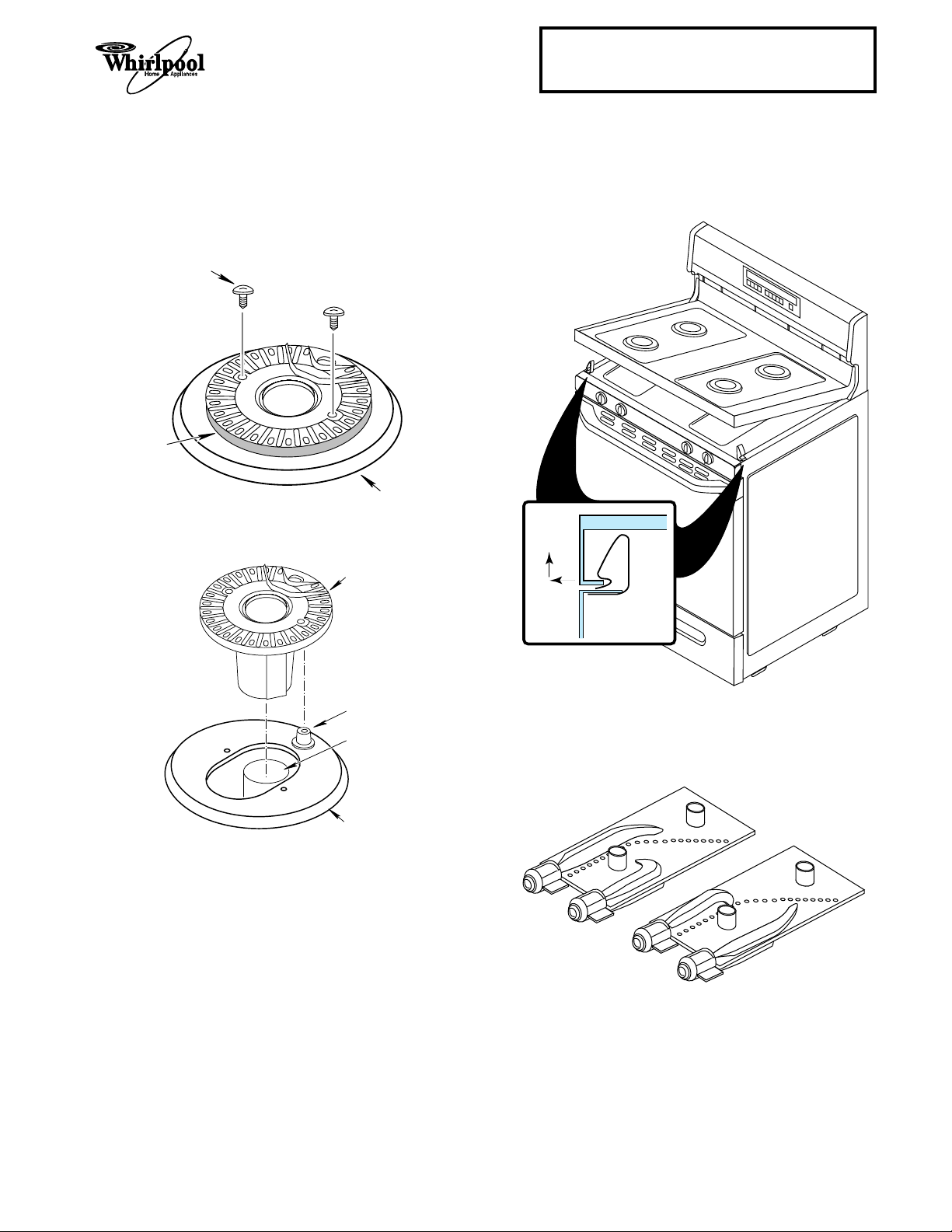
SEALED BURNERS
1. Remove the grates and burner caps from the
burners.
2. Remove the screws from each of the four
burners.
SCREW
BURNER
MAINTOP
3. Lift each burner off the venturi and burner
ignitor.
BURNER
4. Push the front of the maintop to the right while
lifting the right corner and unclip it, then push
to the left and unclip the left corner. Lift the
front of the maintop and prop it up.
PUSH TO
SIDE AND
LIFT TO
UNCLIP
MAINTOP
CLIP
BURNER
IGNITOR
VENTURI
MAINTOP
SIDE PANEL
5. Remove the left and right venturi from the
burner box.
1-11
Page 20
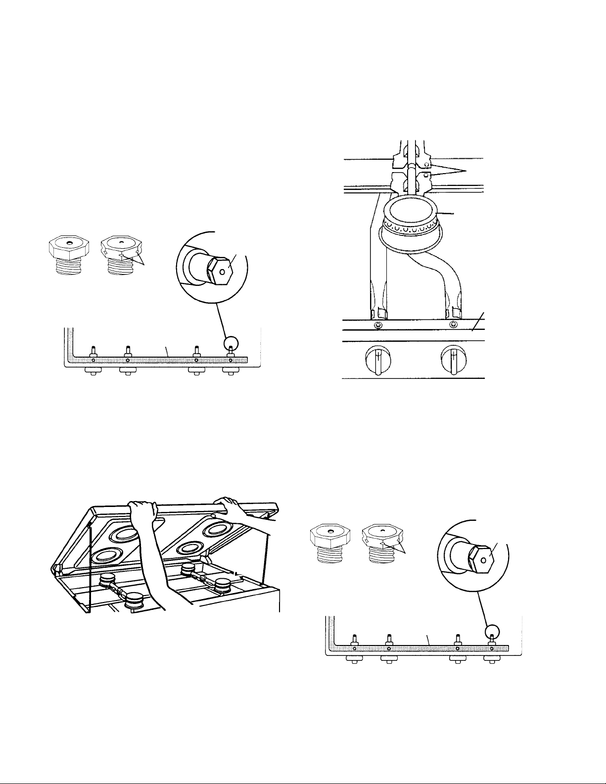
6. Removing one orifice spud at a time, use a
3
/8" combination wrench, and replace the four
color-coded natural gas orifice spuds with the
same color L.P. gas orifice spuds. NOTE:
When you are finished, place the natural gas
orifice spuds in a plastic bag, and store them
in a safe place for possible future use. Also,
keep the literature that was supplied with the
orifice spuds, in the same bag.
3. Remove the four burners from the burner
support bracket and from over the gas valves.
NOTE: If installed, remove the shipping screws
from the burners before you remove them.
burner shipping
screw
Remove and
orifice spuds
notches
#70 #65 gas #65 #68
black brass manifold brass nickel
L.R. L. F. R. F. R.R.
7,500 BTU 8,500 BTU 8,500 BTU 6,500 BTU
replace the
orifice spuds
with the same
color spuds.
7. Reassemble the range.
CONVENTIONAL BURNERS
1. Remove the grates from the burners.
2. Lift the maintop until the support rods lock .
burner
gas valve
4. Removing one orifice spud at a time, use a
3
/8" combination wrench, and replace the natural gas orifice spuds with the L.P. gas orifice
spuds. NOTE: When you are finished, place
the natural gas orifice spuds in a plastic bag,
and store them in a safe place for possible
future use. Also, keep the literature that was
supplied with the orifice spuds, in the same
bag.
orifice spuds
Remove and
replace the
orifice spuds.
notches
brass brass brass brass
L.R. L. F. R. F. R.R.
9,500 BTU 9,500 BTU 9,500 BTU 9,500 BTU
gas manifold
5. Reassemble the range.
1-12
Page 21
Cooking Products Service Manual
Original July, 1996 4321891
© 1996 Whirlpool Corporation
Page 1-13
CHECKING THE MAINTOP BURNER OPERATION
1. Install the maintop burner caps on the burners.
2. If not already done, turn on the gas and
electrical supplies to the range.
3. Push and turn each of the maintop burner
knobs to the LITE position. You should hear a
snapping sound as the burner ignitors spark.
The gas at each burner should ignite after
approximately 4-seconds. When this occurs,
turn the knob to the HI setting. NOTE: Do not
leave the knob in the LITE position after the
burner lights, otherwise the ignitors will continue to spark.
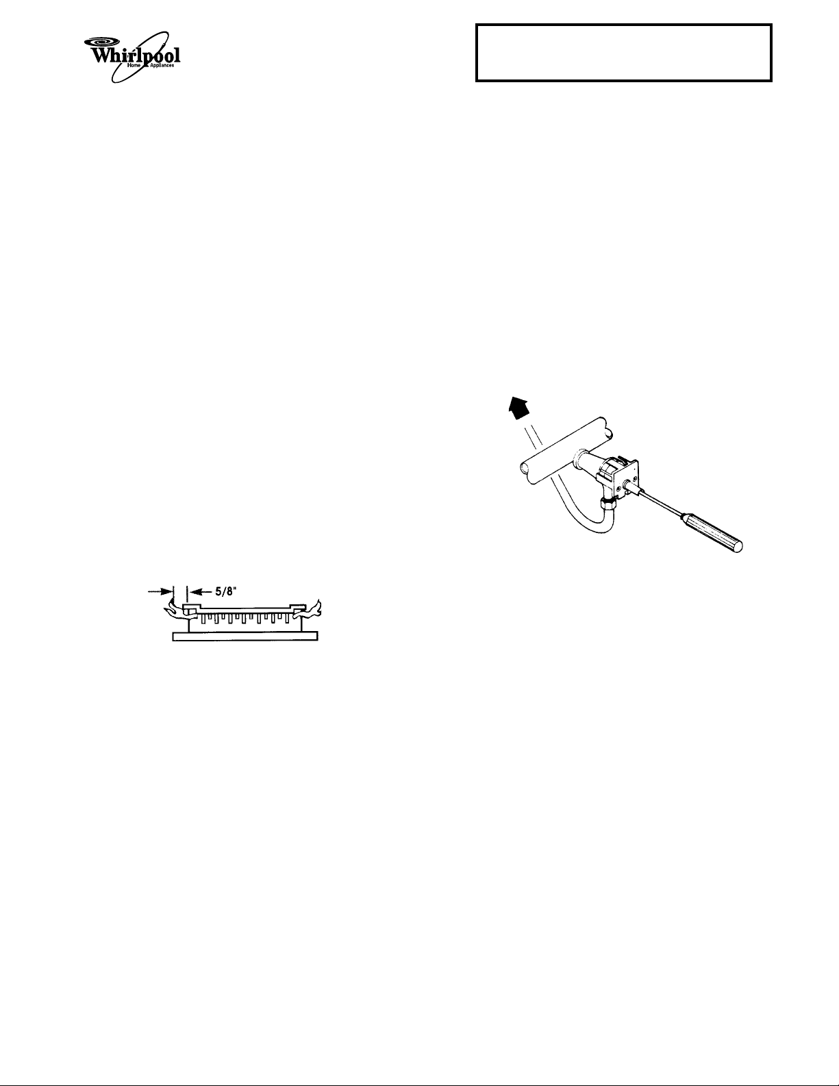
4. Check the maintop burners for the proper
flame. The small inner cone should have a
very distinct blue flame that is approximately
5
/8" long. The outer cone will not be as distinct
as the inner cone. If the flame is noisy or is
blowing, there is too much air during combustion. If the flame is soft and not high enough,
there is not enough air. If either of these
conditions occur, adjust the air shutters, as
shown on the next page.
LO F LAME SETTING
ADJUSTMENT (SOME MODELS)
Some gas ranges have a low flame burner adjustment, located inside the shaft of each gas valve
(see the illustration below). To adjust the flame:
1. Turn the gas valve knob to its LOW, or SIMMER setting, and remove the control knob.
2. Adjust the screw inside the gas valve stem so
that the flame size is as small as possible
without going out when the valve is turned
quickly from the LITE position to WARM position.
3. Turn off the burners and reinstall the knob.
5. Turn the maintop burners off.
1-13
Page 22
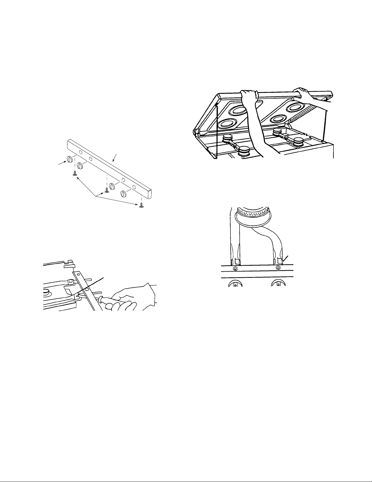
Adjusting The Air Shutters
SEALED BURNERS
1. Lift the maintop and prop it up (see page 1-11
for the procedure).
2. Remove the control knobs.
3. Open the oven door and remove the three
screws from the bottom of the manifold panel,
then pull down slightly on the panel, and pull
it away from the range.
MANIFOLD PANEL
KNOB
SCREWS
4. Use a screwdriver blade, and adjust the air
shutter, as needed. Close the air shutter to
decrease the amount of air to the flame. Open
the air shutter to increase the amount of air to
the flame.
CONVENTIONAL BURNERS
1. Lift the maintop until the support rods lock.
2. Adjust the air shutter openings, as needed.
Close the air shutter to decrease the amount
of air to the flame. Open the air shutter to
increase the amount of air to the flame.
air shutter
venturi air shutter
5. Replace the manifold panel and control knobs
and lower the maintop.
3. Lower the maintop.
1-14
Page 23
Cooking Products Service Manual
Original July, 1996 4321891
© 1996 Whirlpool Corporation
Page 1-15
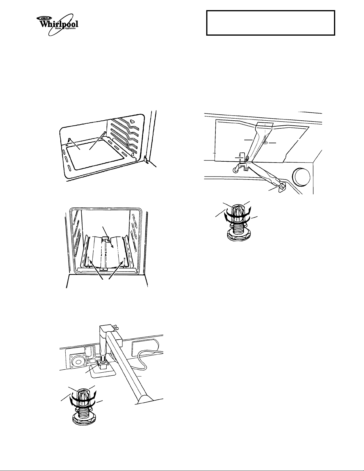
CONVERTING THE OVEN BURNERS FOR L.P. GAS
THE BAKE BURNER
1. Remove the oven racks.
2. Remove the two screws from the oven floor
and remove the floor.
screws
3. Remove the screws from the heat shield over
the bake burner and remove the shield.
heat shield
THE BROIL BURNER
1. Remove the oven racks.
2. Remove the two screws (shown in the illustration) from the broil burner and lift the burner
off the orifice hood.
broil burner
screw
orifice hood
pin
Natural gas L.P. gas
increases decreases flame
flame size in size in this direction
this direction
hood
screw
screws
4. Use a 1/2" combination wrench and turn the
orifice hood at the base of the bake burner
clockwise until it is just snug (approximately
1
/2 turns). NO NOT OVERTIGHTEN THE
2HOOD.
orifice hood bake burner
pin
Natural gas L.P. gas
increases decreases flame
flame size in size in this direction
this direction
hood
3. Use a 1/2" combination wrench and turn the
orifice hood at the base of the broil burner
clockwise until it is just snug (approximately
1
/2 turns). NO NOT OVERTIGHTEN THE
2HOOD.
1-15
Page 24
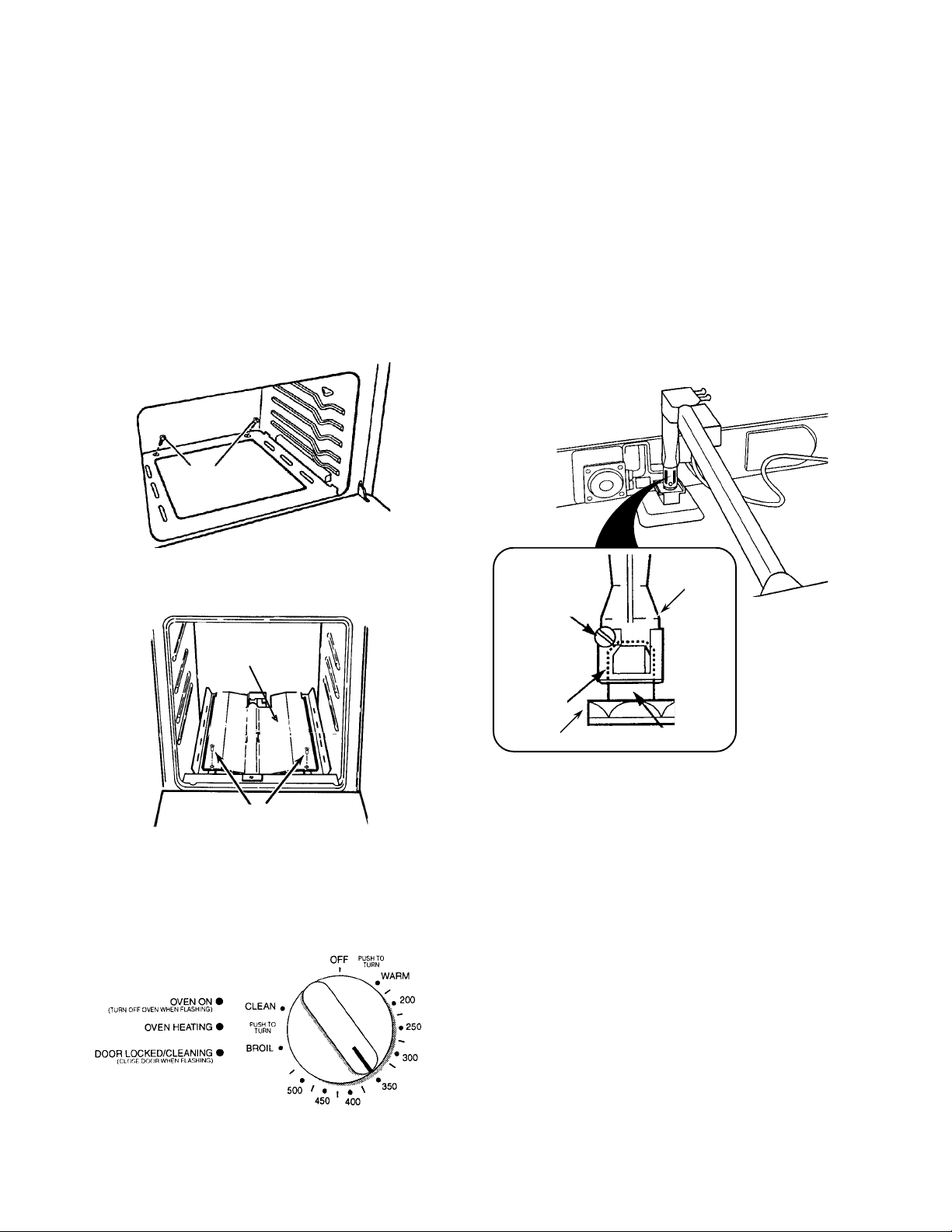
CHECKING THE OVEN BURNER OPERATION
THE BAKE BURNER
NOTE: The bake burner may be controlled by a
knob, or an electronic keypad. Refer to the oven
control that is used on the range you are testing.
Control Knob
1. Remove the oven racks.
2. Remove the two screws from the oven floor
and remove the floor.
screws
5. Check the flame coming from the burner bar.
If the flame is noisy, or is blowing away from
the bar, there is too much air during combustion. If the flame is soft and not high enough,
there is not enough air. If either of these
conditions occur, proceed to the next step.
6. With the burner lit, loosen the locking screw,
and adjust the venturi air shutter opening for
the best flame, then retighten the locking
screw.
3. Remove the screws from the heat shield over
the bake burner and remove the shield.
heat shield
screws
4. Push and turn the oven selector control knob
for a setting of 350˚F. The oven burner should
light in 50- to 60-seconds (the delay is due to
the time it takes for the gas valve to open and
the gas to flow to the burner).
bake burner
venturi
locking screw
air shutter
oven base
gas orifice
7. Turn the oven control knob to OFF. When the
oven cools, reinstall the heat shield, the oven
floor, and the oven racks.
1-16
Page 25

Cooking Products Service Manual
Original July, 1996 4321891
© 1996 Whirlpool Corporation
Page 1-17
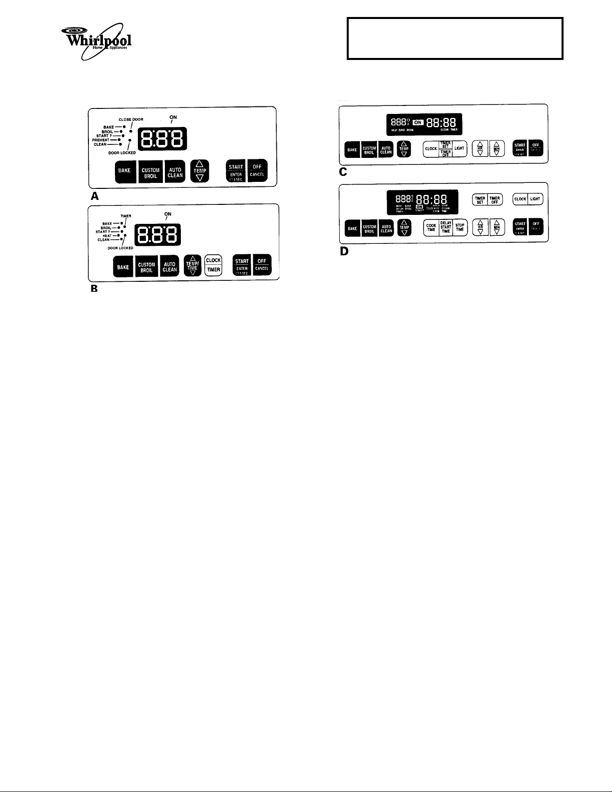
Electronic Oven Control 1
1. Press the BAKE keypad.
• The BAKE indicator will light.
• 350 will appear in the display.
• The START? indicator will begin to flash
after 5-seconds.
2. Press the START/ENTER keypad.
• The PREHEAT or HEAT and ON indicators will appear. NOTE: The PREHEAT
indicator light will not be displayed if the
oven temperature is over 170˚F.
• The display will show the automatic countdown time (10-minutes) needed to preheat the oven for the selected temperature.
• The oven burner should light in 50- to 60seconds (the delay is due to the time it
takes for the gas valve to open and the gas
to flow to the burner).
• After preheat, the PREHEAT indicator light
will go out (Control A only).
• A 1-second tone will sound.
• The countdown timer will change to 350.
3. Open the storage drawer and check the flame
coming from the burner bar. If the flame is
noisy, or is blowing away from the bar, there
is too much air during combustion. If the flame
is soft and not high enough, there is not
enough air. If either of these conditions occur,
refer to step 6 on page 1-16.
4. Press the OFF/CANCEL keypad.
Electronic Oven Control 2
1. Press the BAKE keypad.
• The BAKE indicator will light.
• 350 will appear in the display.
• The START? indicator will begin to flash
after 5-seconds (Control D only).
2. Press the START/ENTER keypad.
• PrE and 10:00 will appear.
• The HEAT and ON indicators will light.
• The oven burner should light in 50- to 60seconds (the delay is due to the time it
takes for the gas valve to open and the gas
to flow to the burner).
• The oven is preheated when the time in
the display counts down to 0:00.
• A 1-second tone will sound.
• PrE will change to 350.
3. Open the storage drawer and check the flame
coming from the burner bar. If the flame is
noisy, or is blowing away from the bar, there
is too much air during combustion. If the flame
is soft and not high enough, there is not
enough air. If either of these conditions occur,
refer to step 6 on page 1-16.
4. Press the OFF/CANCEL keypad.
1-17
Page 26
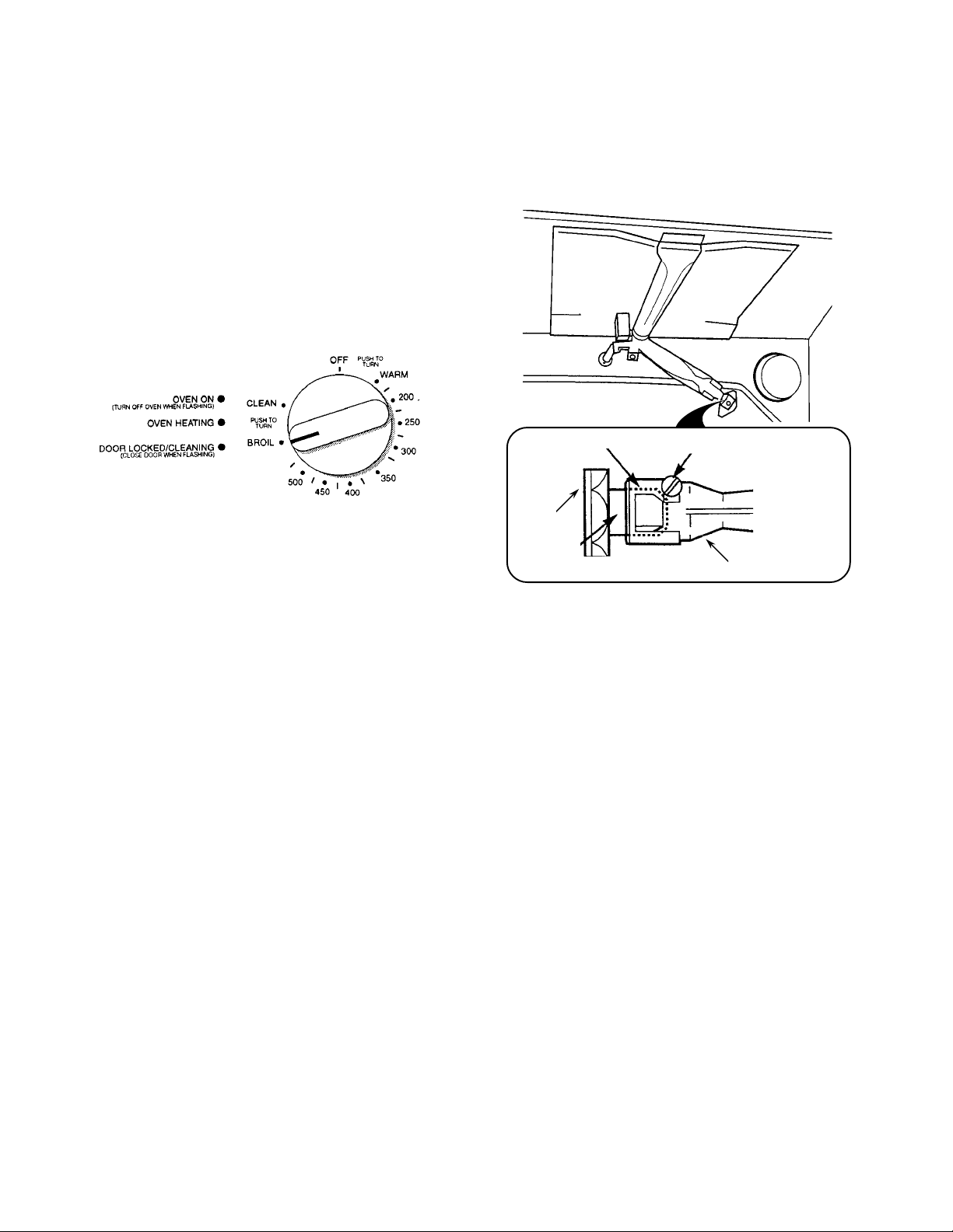
THE BROIL BURNER
NOTE: The broil burner may be controlled by a
knob, or an electronic keypad. Refer to the oven
control that is used on the range you are testing.
Control Knob
1. Push and turn the oven selector control knob
to BROIL. The broil burner should light in 50to 60-seconds (the delay is due to the time it
takes for the gas valve to open and the gas to
flow to the burner).
3. With the burner lit, loosen the locking screw,
and adjust the air shutter opening for the best
flame, then retighten the locking screw.
2. Check the flame coming from the broil burner
bar. If the flame is noisy, or is blowing away
from the bar, there is too much air during
combustion. If the flame is soft and not high
enough, there is not enough air. If either of
these conditions occur, proceed to the next
step.
air shutter
rear of
oven liner
gas orifice
locking screw
broil burner venturi
4. Turn the oven control knob to OFF.
1-18
Page 27
Cooking Products Service Manual
Original July, 1996 4321891
© 1996 Whirlpool Corporation
Page 1-19
Electronic Oven Control 1
1. Press the CUSTOM BROIL keypad.
• 525 or HI will appear in the display.
• The BROIL indicator will light.
• The START? indicator will begin to flash
after 5-seconds.
2. Press the START/ENTER keypad.
• The HEAT (Control B only) and ON indicators will light.
• The broil burner should light in 50- to 60seconds (the delay is due to the time it
takes for the gas valve to open and the gas
to flow to the burner).
3. Open the storage drawer and check the flame
coming from the broil burner bar (use a mirror,
if necessary). If the flame is noisy, or is blowing away from the bar, there is too much air
during combustion. If the flame is soft and not
high enough, there is not enough air. If either
of these conditions occur, refer to step 3 on
page 1-18.
Electronic Oven Control 2
1. Press the CUSTOM BROIL keypad.
• HI will appear in the display.
• The BROIL indicator will light.
• The START? indicator will begin to flash
after 5-seconds.
2. Press the START/ENTER keypad.
• The HEAT and ON indicators will light.
• The broil burner should light in 50- to 60seconds (the delay is due to the time it
takes for the gas valve to open and the gas
to flow to the burner).
3. Open the storage drawer and check the flame
coming from the broil burner bar (use a mirror,
if necessary). If the flame is noisy, or is blowing away from the bar, there is too much air
during combustion. If the flame is soft and not
high enough, there is not enough air. If either
of these conditions occur, refer to step 3 on
page 1-18.
4. Press the OFF/CANCEL keypad.
4. Press the OFF/CANCEL keypad.
1-19
Page 28
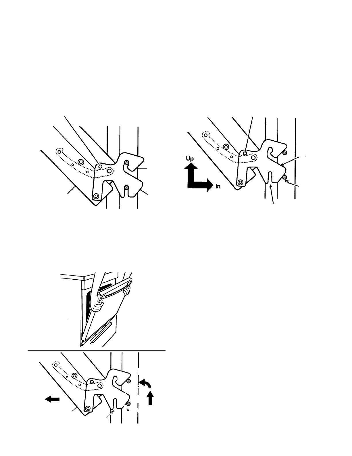
REMOVING/REINSTALLING THE OVEN DOOR
To remove the oven door:
1. Open the door approximately half way and
install the shipping pin (supplied with the
range), or a
hangers on each side of the door.
insert shipping pin or
allen wrench in this hole
oven door hinge
2. Close the oven door as far as the shipping
pins will allow.
3
/16" allen wrench, into the hinge
range
hanger
To reinstall the oven door:
1. Insert the hinge hangers into the front slots of
the range as far as they will go, then lift the
door while you push against it, and hook the
hinge slots in the pins.
remove shipping pin or
allen wrench from this hole
hinge
hanger
pin
slot
2. Remove the shipping pins and close the door.
3. Lift the door as far as possible so the slots in
the hinge hangers clear the pins, then rotate
the top toward you, and pull the hinges from
the slots in the front of the range.
2. ROTATE
3. PULL
oven door
1. LIFT
slot pin
1-20
Page 29
THEORY OF OPERATION
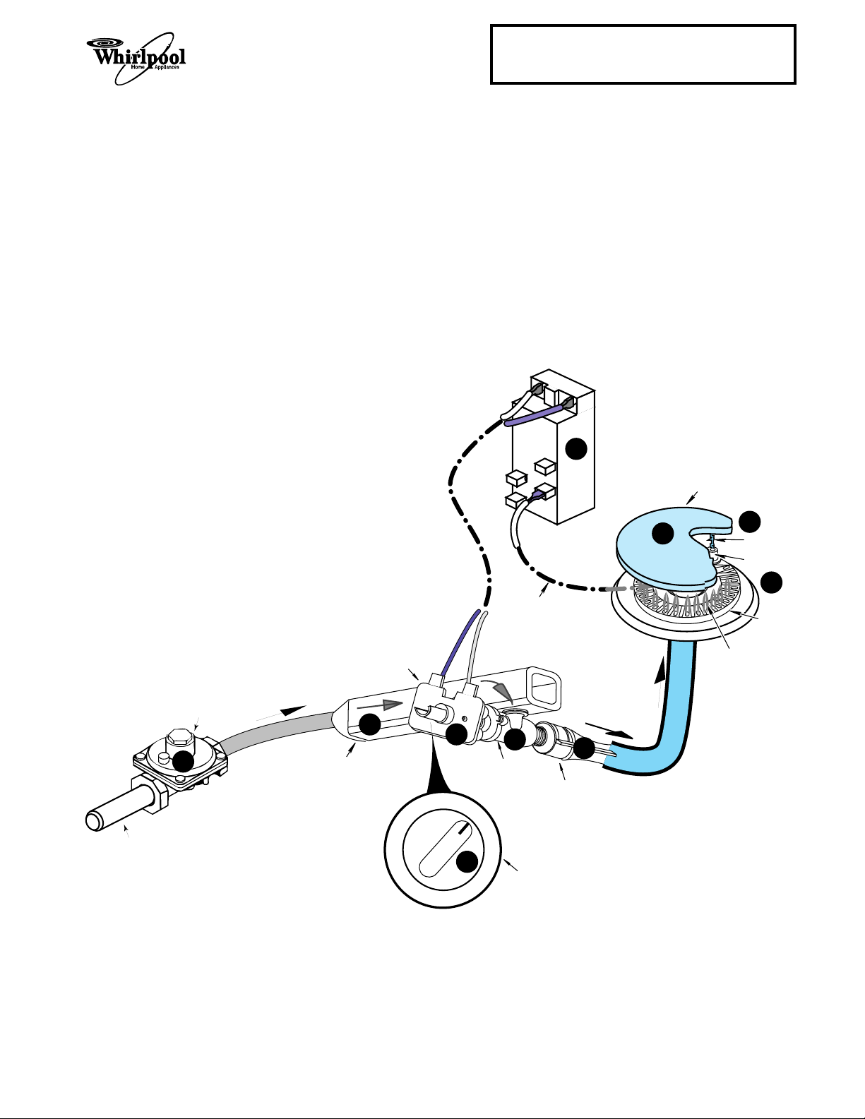
THE COOKTOP BURNERS
Refer to the illustration below while you read
this description.
When a surface burner control knob is turned
to the “lite” position, the gas valve r opens,
and gas from the pressure regulator s flows
into the manifold t, and through the open
valve. As gas passes through the valve and its
orifice, it is directed into the venturi u, where
it mixes with air to create the proper mixture
necessary for combustion.
At the same time, line voltage is applied through
the ignitor switch v to the ignitor module w,
which produces high-voltage pulses to all of
the burner ignitors x. The pulses cause a
spark y to occur between the burner ignitor
and the grounded burner cap z, which ignites
the gas and air mixture at the burner head, and
produces a flame.
Cooking Products Service Manual
Original July, 1996 4321891
© 1996 Whirlpool Corporation
IGNITOR
MODULE
7
Page 2-1
GAS INLET
PRESSURE
REGULATOR
3
GAS FLOW
IGNITOR SWITCH
GAS
MANIFOLD
4
120 VAC
LINE VOLTAGE
6
OFF
LITE
1
2
GAS VALVE
BURNER
CONTROL
HIGH VOLTAGE
PULSES
TO BURNER
IGNITOR
VENTURI
KNOB
GAS FLOW
5
BURNER CAP
10
9
SPARK
BURNER
IGNITOR
8
BURNER
BURNER FLAME
2-1
Page 30
IGNITOR SYSTEM OVERVIEW
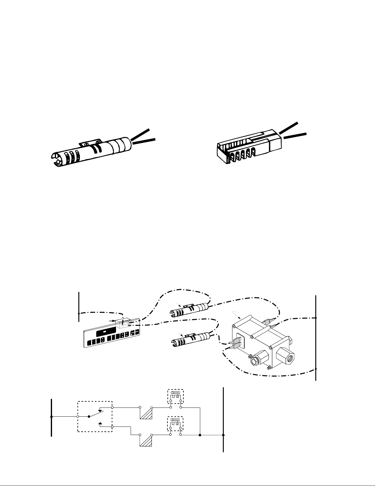
This gas range uses two Carborundum ignitors to provide a source for igniting gas from
the bake and broil burners. Norton ignitors
were previously used in the Whirlpool gas
ranges, and both of these ignitors operate the
same way. The only differences are in the
design (see the illustrations), and in the current ratings.
Carborundum Ignitor
2.5 - 3.0 Amps
IGNITOR SYSTEM OPERATION
The oven ignitor system in these Whirlpool
gas ranges has the following three main components, and is wired in a series-parallel circuit (see the illustration below):
1. An Electronic Oven Control (EOC).
2. Two Carborundum Ignitors (Bake &
Broil).
3. Dual Gas Safety Valve.
L1
BROIL IGNITOR
RELAY
CUSTOM
BAKE
O
F
HEAT BAKE BROIL LOCKED CLEAN TIMER
AUTO
CLEAN
BROIL
ON
TA
PF
DELAY
TIMER
CLOCK
SET
TIME
ELECTRONIC
OVEN CONTROL
(EOC)
S
N
E
MIN
HR
STOP
TIMER
OFF
OFF
RT
CANCEL
TER
5 SEC
BAKE IGNITOR
A Carborundum ignitor uses a round design,
and limits the operating current flow to between 2.5 and 3.0 amperes.
A Norton ignitor uses a rectangular design,
and limits the operating current flow to between 3.2 and 3.6 amperes.
Norton Ignitor
3.2 - 3.6 Amps
All of the self-clean gas ranges use these
components. When the EOC is set to the bake
or broil mode and a temperature is selected,
the relay on the EOC closes, and provides
power to the ignitor. With power applied, current flows through the ignitor circuit, and the
ignitor begins to heat and glow.
N
DUAL GAS
SAFETY VALVE
ELECTRONIC OVEN CONTROL
L1
RELAY
N
BROIL VALVE
BROIL IGNITOR
BAKE VALVE
BAKE IGNITOR
2-2
Page 31

Cooking Products Service Manual
Original July, 1996 4321891
© 1996 Whirlpool Corporation
Page 2-3
As the ignitor heats up and its electrical resistance decreases, current flow increases
through the bimetal arm heater inside the dual
gas safety valve. When the ignitor becomes
hot enough and its electrical resistance low
enough, sufficient current is provided (2.5 to
3.0 amps) through the bimetal arm heater, to
cause the arm to flex. This opens the gas
valve and allows gas to flow to the burner,
where the heat from the ignitor (approximately
2500˚F) ignites it, and produces a flame.
GAS OUTLET
BIMETAL ARM
LOW CURRENT
FROM IGNITOR
BIMETAL HEATER
VALVE CLOSED
The ignitor will remain energized at all times
when the burner is lit. As soon as the oven
reaches its selected temperature, the EOC
relay opens, and power is removed from the
circuit. Once this occurs, the ignitor cools, and
the bimetal arm flexes and closes the gas
safety valve, turning off the gas to the burner
and extinguishing the flame.
GAS OUTLET
GAS VALVE
HIGH CURRENT
FROM IGNITOR
HEAT FROM
BIMETAL HEATER
FLEXES ARM
OPENS
GAS INLET
IGNITOR
DUAL GAS
SAFETY VALVE
GAS INLET
BURNER
GAS FLOW
2-3
Page 32

TROUBLESHOOTING THE IGNITOR SYSTEM
Refer to the illustration below while you read
the following troubleshooting information.
Ignitor Does Not Glow
Diagram B—Broil:
With the EOC programmed
for the Broil mode, you should obtain a reading of 120 VAC between P2-1 and Neutral.
1. Disconnect or remove the ignitor and measure its resistance. Cold resistance should
be between 50 and 150 Ohms. (The value
of the resistance is not important as long
as the ignitor is not open or shorted).
2. Check the internal fuses, switches, and
120 VAC power supply.
3. If power is working:
a) Disconnect the oven power and re-
move wires at “B” and “C”.
1. Check continuity between wire “B”
and terminal “C”. If continuity is
present, go to Step 4.
b) If continuity is NOT present, remove
wire at “D” and probe terminals “D”
and “C” for continuity. If NO continuity, replace the bimetal valve.
c) If continuity is present at “D” and “C”,
probe wires “B” and “D”. If NO continuity, replace the ignitor.
4. Check for
120 VAC
at the following locations, and the relay(s) on the Electronic
Oven Control you are servicing. Also refer to the wiring diagrams on the next
page.
PROGRAM DIAGRAM A DIAGRAM B
Bake P3-1 to P2-1 P2-3 to P2-4
Broil P3-1 to P2-1 P2-2 to P2-1
Ignitor Glows With No Ignition
1. Check that gas is turned on to the range.
2. Turn the power on and set the thermostat
to 350˚F.
3. Check the ampere draw at the bimetal
valve.
a) Using a wraparound ammeter, test one
leg for ampere draw at "D" or "C".
1. NORTON (flat) Ignitor - 3.2 to 3.6
amps.
2. CARBORUNDUM (round) Ignitor-
2.5 to 3.0 amps.
If the ampere draw is NOT within the
proper range, replace the ignitor.
b) If the correct ampere draw is present,
replace the valve.
For safety purposes, when measuring the
current flow through the ignitor circuit, shut
off the main, or the oven gas shut-off valve.
NOTE: A simple circuit is shown. The actual
circuit may include fuses, clock, selector
switch, or other items.
ELECTRONC OVEN CONTROL
O
ON
350
F
BAKE
CUSTOM
BROIL
CLEAN
10:30
HEAT BAKE BROIL LOCKED CLEAN TIMER
CLOCK
DELAY
TIMER
TIME
SET
AUTO
STOP
TIMER
HR MIN
OFF
AB
OFF
START
ENTER
CANCEL
5 SEC
L1
Diagram A—Bake:
With the EOC programmed
for the Bake mode, you should obtain a reading of 120 VAC between P3-1 and P2-4, and
between P3-4 and P2-1.
Diagram A—Broil:
With the EOC programmed
for the Broil mode, you should obtain a reading of 120 VAC between P3-2 and P2-1, and
between P3-1 and P2-2.
Diagram B—Bake:
With the EOC programmed
for the Bake mode, you should obtain a reading of 120 VAC between P2-4 and Neutral.
DUAL GAS
SAFETY VALVE
2-4
IGNITOR
C
D
BURNER
N
Page 33

Cooking Products Service Manual
Original July, 1996 4321891
© 1996 Whirlpool Corporation
Page 2-5
L1
BK
OVEN
TEMP
SENSOR
BK
N
OVEN LIGHT
GND
BK
OVEN CONTROL
TRANSFORMER
V
V
P3-1
P2-1
P1-6
P1-7
LATCH SOLENOID
RELAY
BROIL
RELAY
BAKE
RELAY
W
P5
P1-1
P1-5
BU
P1-3
BR
P4
P3-4
BU
P3-2
W
P2-4
P2-2
W
W
DOOR
LIGHT SW.
LATCH
SOLENOID
W
BK
YY
GY
DOOR
LATCH SW.
W
RR
BAKE VALVE
BAKE IGNITOR
BU
BROIL VALVE
BROIL IGNITOR
W
N.O.
L1
BK
BK
OVEN TEMP
SENSOR
BK
BK
DOOR
SW.
GND
Wiring Diagram A
Wiring Diagram B
OVEN CONTROL
P4-3 P4-1
OVEN LIGHT
TRANSFORMER
P4-4
P4-5
P3-1
P3-2
P2-1
P2-4
BK
BR
BU
R
DOOR LOCK
SOLENOID
GY
GY
BROIL IGNITOR
BAKE IGNITOR
LATCH SW.
N.O.
COM
BU
BROIL VALVE
RW
BAKE VALVE
Y
P3-3
Y
P3-4
LATCH SOLENOID
V
V
P3-6
P3-7
P2-2
P2-3
G
P3-5
RELAY
BROIL RELAY
BAKE RELAY
GND
W
W
DOOR
BU
R
N
W
W
2-5
Page 34

THE OVEN CONTROL
Refer to the illustrations on pages 2-6 and
2-7 while you read this description.
When the range is plugged in, line voltage is
applied to the electronic oven control.
L1
BK
BK
OVEN CONTROL
OVEN
TEMP
SENSOR
V
V
P1-6
P1-7
TRANSFORMER
LATCH SOLENOID
RELAY
The voltage travels through the low voltage
transformer to the neutral side of the line, and
turns the oven control on. “PF” is displayed on
the control display.
OVEN LIGHT
P5
P1-1
P1-5
P1-3
P4
W
DOOR
LIGHT SW.
BU
BR
W
YY
LATCH
SOLENOID
BK
W
GY
N.O.
DOOR
LATCH SW.
N
GND
W
BK
BK
W
P3-1
P2-1
BROIL
RELAY
BAKE
RELAY
P3-4
P3-2
P2-4
P2-2
RR
BAKE VALVE
BU
BAKE IGNITOR
W
BROIL IGNITOR
W
BU
BROIL VALVE
2-6
Page 35

L1
N
BK
BK
V
Y
Y
V
BU
RW
R
R
BU
BU
BR
W
W
W
W
BK
BK
G
GND
OVEN CONTROL
TRANSFORMER
P3-3
P4-3 P4-1
P4-4
P4-5
P3-4
P3-6
P3-7
P2-2
P2-3
P3-5
P2-1
P2-4
LATCH SOLENOID
RELAY
DOOR LOCK
SOLENOID
BAKE VALVE
BROIL VALVE
BAKE IGNITOR
BROIL IGNITOR
OVEN LIGHT
GND
BAKE RELAY
BROIL RELAY
GY
GY
P3-1
P3-2
DOOR
LATCH SW.
DOOR
SW.
OVEN TEMP
SENSOR
N.O.
COM
O
ON
F
HEAT BAKE BROIL LOCKED CLEAN TIMER
PF
Cooking Products Service Manual
Original July, 1996 4321891
© 1996 Whirlpool Corporation
Page 2-7
BAKE
CUSTOM
BROIL
AUTO
CLEAN
CLOCK
TIME
DELAY
TIMER
SET
STOP
TIMER
OFF
HR MIN
START
ENTER
5 SEC
OFF
CANCEL
2-7
Page 36

THE BAKE FUNCTION
Refer to the illustrations on pages 2-8 and
2-9 while you read this description.
When the unit is plugged in and line voltage is
applied to the electronic oven control, the
following keyboard actions are used to set the
BAKE function:
• The clock is set to the time-of-day.
• The BAKE keypad is selected.
• The BAKE temperature is selected.
L1
BK
BK
OVEN CONTROL
OVEN
TEMP
SENSOR
V
V
P1-6
P1-7
TRANSFORMER
LATCH SOLENOID
RELAY
When the preceding events occur, the BAKE
relay energizes, and its contacts close. This
provides an electrical circuit through the BAKE
ignitor and the BAKE valve to the neutral side
of the line*.
As electrical current flows through the BAKE
ignitor, it heats up. When the BAKE valve
opens, gas flows through the burner, and the
hot ignitor ignites the gas and air mixture, and
a flame is produced.
OVEN LIGHT
GND
P5
P1-1
P1-5
P1-3
P4
W
DOOR
LIGHT SW.
BU
BR
W
YY
LATCH
SOLENOID
W
BK
GY
N.O.
DOOR
LATCH SW.
N
W
BK
BK
P3-1
BROIL
RELAY
P2-1
BAKE
RELAY
W
= Oven Control On
= BAKE Circuit
* The BAKE path is also through the normally
closed (N.C.) contacts of the BROIL relay.
2-8
P3-4
P3-2
P2-4
P2-2
RR
BAKE VALVE
BU
BAKE IGNITOR
W
BROIL IGNITOR
W
BU
BROIL VALVE
Page 37

Cooking Products Service Manual
Original July, 1996 4321891
© 1996 Whirlpool Corporation
O
BAKE TEMPERATURE TIME OF DAY
350
HEAT BAKE BROIL LOCKED CLEAN TIMER
ON
F
10:30
Page 2-9
L1
BK
BK
OVEN TEMP
SENSOR
DOOR
SW.
V
V
BAKE
CUSTOM
BROIL
AUTO
CLEAN
OVEN CONTROL
P4-3 P4-1
TRANSFORMER
Y
P3-3
Y
P3-4
LATCH SOLENOID
P3-6
P3-7
RELAY
P4-4
P4-5
P3-1
P3-2
CLOCK
TIME
BK
DELAY
TIMER
SET
BR
STOP
TIMER
OFF
OVEN LIGHT
DOOR LOCK
SOLENOID
GY
GY
HR MIN
COM
N.O.
START
ENTER
5 SEC
W
W
DOOR
LATCH SW.
OFF
CANCEL
GND
N
W
W
BK
G
GND
= Oven Control On
= BAKE Circuit
P2-2
P2-3
P3-5
BROIL RELAY
BAKE RELAY
P2-1
P2-4
2-9
BU
R
BU
BROIL IGNITOR
BAKE IGNITOR
BU
BROIL VALVE
RW
BAKE VALVE
R
Page 38

THE BROIL FUNCTION
Refer to the illustrations on pages 2-10 and
2-11 while you read this description.
When the unit is plugged in and line voltage is
applied to the electronic oven control, the
following keyboard actions are used to set the
BROIL function:
• The clock is set to the time-of-day.
• The CUSTOM BROIL keypad is se-
lected.
L1
BK
BK
OVEN CONTROL
OVEN
TEMP
SENSOR
V
V
P1-6
P1-7
TRANSFORMER
LATCH SOLENOID
RELAY
When the preceding events occur, the BROIL
relay energizes, and its contacts close. This
provides an electrical circuit through the BROIL
ignitor and the BROIL valve to the neutral side
of the line*.
As electrical current flows through the BROIL
ignitor, it heats up. When the BROIL valve
opens, gas flows through the burner, and the
hot ignitor ignites the gas and air mixture, and
a flame is produced.
OVEN LIGHT
GND
P5
P1-1
P1-5
P1-3
P4
W
LIGHT SW.
BU
BR
DOOR
LATCH
SOLENOID
W
YY
W
BK
GY
DOOR
LATCH SW.
N.O.
N
W
BK
BK
P3-1
P2-1
W
= Oven Control On
= BROIL Circuit
BROIL
RELAY
BAKE
RELAY
* The BROIL path is also through the normally
closed (N.C.) contacts of the BAKE relay.
P3-4
P3-2
P2-4
P2-2
2-10
RR
BAKE VALVE
BU
BAKE IGNITOR
W
BROIL IGNITOR
W
BU
BROIL VALVE
Page 39

Cooking Products Service Manual
L1
N
BK
BK
V
Y
Y
V
BU
RW
R
R
BU BU
BR
W
W
W
W
BK
BK
G
GND
OVEN CONTROL
TRANSFORMER
P3-3
P4-3 P4-1
P4-4
P4-5
P3-4
P3-6
P3-7
P2-2
P2-3
P3-5
P2-1
P2-4
LATCH SOLENOID
RELAY
DOOR LOCK
SOLENOID
BAKE VALVE
BROIL VALVE
BAKE IGNITOR
BROIL IGNITOR
OVEN LIGHT
GND
BAKE RELAY
BROIL RELAY
GY
GY
P3-1
P3-2
DOOR
LATCH SW.
DOOR
SW.
OVEN TEMP
SENSOR
N.O.
COM
= Oven Control On
= BROIL Circuit
Original July, 1996 4321891
© 1996 Whirlpool Corporation
Page 2-11
BROIL TEMPERATURE TIME OF DAY
CUSTOM
BAKE
BROIL
HI
HEAT BAKE BROIL LOCKED CLEAN TIMER
AUTO
CLEAN
O
ON
F
10:30
TIME
DELAY
TIMER
SET
CLOCK
STOP
TIMER
OFF
HR MIN
START
ENTER
5 SEC
OFF
CANCEL
2-11
Page 40

THE CLEAN FUNCTION
Refer to the illustrations on pages 2-12 and
2-13 while you read this description.
When the unit is plugged in and line voltage is
applied to the electronic oven control, the
following keyboard actions are used to set the
oven CLEAN function:
• The CLEAN function is selected.
• The desired cleaning time is selected.
When the preceding events occur, the BAKE
relay energizes, and its contacts close. This
provides an electrical circuit through the BAKE
ignitor and the BAKE valve to the neutral side
of the line.
L1
BK
= Oven Control On
= BAKE Circuit
= LATCH Circuit
BK
OVEN CONTROL
P5
Because the oven reaches extremely hot temperatures, the oven door is latched during the
CLEAN cycle, and remains latched until the
oven has cooled to a safe temperature.
The door latching operation occurs when the
LATCH SOLENOID relay closes, and electrical current flows through the LATCH SOLENOID.
After the CLEAN cycle has been completed,
the door latch will release when the oven
temperature drops below 400˚F.
N
OVEN LIGHT
GND
W
W
BK
W
OVEN
TEMP
SENSOR
BK
BK
P1-1
TRANSFORMER
V
V
W
P1-6
P1-7
LATCH SOLENOID
RELAY
P3-1
BROIL
RELAY
P2-1
BAKE
RELAY
P1-5
P1-3
P4
P3-4
P3-2
P2-4
P2-2
DOOR
LIGHT SW.
BU
SOLENOID
BR
RR
BU
W
W
YY
LATCH
BAKE IGNITOR
BROIL IGNITOR
GY
LATCH SW.
W
BAKE VALVE
BU
BROIL VALVE
DOOR
N.O.
2-12
Page 41

O
ON
F
HEAT BAKE BROIL LOCKED CLEAN TIMER
3 :50
Cooking Products Service Manual
Original July, 1996 4321891
© 1996 Whirlpool Corporation
CLEAN TIME
Page 2-13
L1
BK
BK
DOOR
SW.
OVEN TEMP
SENSOR
5 SEC
OFF
CANCEL
BAKE
CUSTOM
BROIL
AUTO
CLEAN
CLOCK
TIME
DELAY
TIMER
SET
STOP
TIMER
OFF
HR MIN
START
ENTER
N
OVEN CONTROL
GND
W
W
P4-3 P4-1
OVEN LIGHT
TRANSFORMER
Y
P3-3
Y
P3-4
LATCH SOLENOID
RELAY
V
P3-6
P3-7
P4-4
P4-5
P3-1
P3-2
BK
BR
DOOR LOCK
SOLENOID
GY
GY
COM
W
W
DOOR
LATCH SW.
N.O.
V
BK
GND
= Oven Control On
= BAKE Circuit
= LATCH Circuit
P2-2
BROIL RELAY
P2-3
G
P3-5
BAKE RELAY
P2-1
P2-4
BU
R
BROIL IGNITOR
BAKE IGNITOR
BU
BROIL VALVE
RW
BAKE VALVE
BU
R
2-13
Page 42

THE OVEN LIGHT
Refer to the illustration while you read this
description.
When the range is plugged in, line voltage is
applied to the electronic oven control.
O
F
HEAT BAKE BROIL LOCKED CLEAN TIMER
3 :50
When the door switch, or the switch in the
oven control closes, the line voltage travels
through the light to the neutral side of the line.
L1
BAKE
BK
BK
OVEN TEMP
SENSOR
DOOR
SW.
CUSTOM
BROIL
V
V
AUTO
CLEAN
TEMP
OVEN CONTROL
P4-3 P4-1
TRANSFORMER
Y
P3-3
Y
P3-4
LATCH SOLENOID
P3-6
P3-7
RELAY
COOK
TIME
P4-4
P4-5
P3-1
P3-2
TIMER
SET
TIMER
OFF
BK
BR
LIGHT
OVEN LIGHT
DOOR LOCK
SOLENOID
GY
GY
HR MIN
N.O.
COM
W
W
DOOR
LATCH SW.
START
ENTER
5 SEC
GND
OFF
CANCEL
N
W
W
BK
GND
= Oven Control On
= LIGHT Circuit
P2-2
BROIL RELAY
P2-3
G
P3-5
BAKE RELAY
P2-1
P2-4
BU
R
BROIL IGNITOR
BAKE IGNITOR
BU
BROIL VALVE
RW
BAKE VALVE
BU
R
2-14
Page 43

COMPONENT ACCESS
Cooking Products Service Manual
Original July, 1996 4321891
© 1996 Whirlpool Corporation
Page 3-1
This section of the manual instructs you on how to
service the individual components inside the sealed
burner and conventional burner gas ranges.
SEALED BURNER MODELS
UPPER CONSOLE
IGNITOR MODULE
SEALED BURNER
& BURNER IGNITOR
VENTURI
BROIL BURNER
& IGNITOR
OVEN DOOR
LATCH
GAS VALVE
& SPARK
IGNITOR SWITCH
PRESSURE
REGULATOR
BAKE BURNER
& IGNITOR
The illustrations below show the location of all the
major components in the range. Refer to them as
necessary.
OVEN CONTROL
MANUAL OVEN
LIGHT SWITCH
LATCH SENSING
SWITCHES & DOOR
LATCH SOLENOID
OVEN LIGHT
OVEN TEMPERATURE
SENSOR
AUTOMATIC OVEN
LIGHT SWITCH
GAS SAFETY
VALVE
CONVENTIONAL BURNER MODELS
OVEN CONTROL
MANUAL OVEN
LIGHT SWITCH
OVEN TEMPERATURE
SENSOR
AUTOMATIC OVEN
LIGHT SWITCH
GAS SAFETY
VALVE
LATCH SENSING
SWITCHES & DOOR
LATCH SOLENOID
OVEN LIGHT
BURNER IGNITOR
CONVENTIONAL
BURNER
BROIL BURNER
& IGNITOR
OVEN DOOR
LATCH
GAS VALVE
& SPARK IGNITOR
SWITCH
PRESSURE
REGULATOR
BAKE BURNER
& IGNITOR
UPPER CONSOLE
IGNITOR MODULE
3-1
Page 44

REMOVING THE MAINTOP
Sealed Burner Models
WARNING
Electrical Shock Hazard
Disconnect from electrical supply before servicing unit.
Failure to do so could result in death or electrical shock.
CAUTION: When you work on the gas range, be
careful when handling the sheet metal parts. Sharp
edges may be present, and you can cut yourself if
you are not careful.
4. Lift each burner off the venturi and burner
ignitor.
BURNER
BURNER
IGNITOR
VENTURI
1. Turn off the gas to the range and disconnect
the power cord from the wall outlet.
2. Remove the grates and burner caps from the
maintop.
3. Remove the screws from each burner.
SCREW
BURNER
MAINTOP
MAINTOP
5. Push the front of the maintop to the right while
lifting the right corner and unclip it, then push
to the left and unclip the left corner. Lift the
maintop and prop it up.
PUSH TO
SIDE AND
LIFT TO
UNCLIP
MAINTOP
CLIP
SIDE PANEL
If you are removing the maintop, continue to step 6
on the next page.
3-2
Page 45

Cooking Products Service Manual
HINGE PIN
MOUNTING
SCREW
UPPER
ACCESS
PANEL
MAINTOP
INSERT HINGE
PIN IN BRACKET
HOLE IN UPPER
ACCESS PANEL
HINGE
BRACKET
HINGE PIN
UPPER
CONSOLE
MAINTOP
Original July, 1996 4321891
© 1996 Whirlpool Corporation
Page 3-3
6. Pull the range away from the wall so that you
can access the back.
7. From behind the range, remove the upper and
lower access covers and the lower heat shield.
IGNITOR MODULE
UPPER
CONSOLE
ROUTE WIRES
THROUGH
UPPER CONSOLE
BURNER
IGNITOR
(4)
UPPER
ACCESS COVER
LOWER
HEAT
SHIELD
9. Slide the maintop to the right so that the left
hinge pin is free of the hinge bracket, (see the
inset), and then to the left so that the right
hinge pin is free of its bracket, then set the
maintop with the burner ignitors on top of the
range. CAUTION: Be careful not to pull on
the spark ignitor wires or you will pull them
out of the ignitors.
LOWER
ACCESS
COVER
8. Unplug the burner ignitor wires from the ignitor module, pull them through the back of the
upper console to the front, and remove them
from the maintop.
BURNER IGNITOR
MAINTOP
10. Remove the hinge pins from the old maintop
and install them on the new one.
11. Install the new maintop and burner ignitors
and reassemble the range.
3-3
Page 46

REMOVING THE MAINTOP
HINGE PIN
MOUNTING
SCREW
UPPER
ACCESS
PANEL
MAINTOP
INSERT HINGE
PIN IN BRACKET
HOLE IN UPPER
ACCESS PANEL
Conventional Burner Models
WARNING
Electrical Shock Hazard
Disconnect from electrical supply before servicing unit.
Failure to do so could result in death or electrical shock.
CAUTION: When you work on the gas range, be
careful when handling the sheet metal parts. Sharp
edges may be present, and you can cut yourself if
you are not careful.
1. Turn off the gas to the range and disconnect
the power cord from the wall outlet.
2. Remove the grates from the maintop.
3. Lift the maintop as far as it will go and unsnap
the support rods from the body sides.
4. Slide the maintop to the left so that the hinge
pin is free of the right hinge bracket, (see the
inset), and to the right so that it is free of the
left bracket, then remove the maintop.
UPPER
CONSOLE
HINGE
BRACKET
HINGE PIN
MAINTOP
5. Remove the hinge pins from the old maintop
and mount them to the new one.
6. Install the new maintop.
3-4
Page 47

Cooking Products Service Manual
Original July, 1996 4321891
© 1996 Whirlpool Corporation
REMOVING A SEALED BURNER & A VENTURI
REMOVING A VENTURI
Page 3-5
WARNING
Electrical Shock Hazard
Disconnect from electrical supply before servicing unit.
Failure to do so could result in death or electrical shock.
CAUTION: When you work on the gas range, be
careful when handling the sheet metal parts. Sharp
edges may be present, and you can cut yourself if
you are not careful.
REMOVING A BURNER
1. Turn off the gas to the range and disconnect
the power cord from the wall outlet.
2. Remove the grates and burner caps from the
maintop.
3. Remove the screws from the defective burner.
SCREW
1. Turn off the gas to the range and disconnect
the power cord from the wall outlet.
2. Lift the maintop and prop it up (use the procedure on page 3-2).
3. Lift the defective venturi from the burner box
and replace it with a new one.
4. Lift the top of the coil around both venturi
openings so they are even with the top.
5. Reassemble the range.
SLIDE COIL UP
TO TOP OF VENTURI
INSERT TAB
INTO SLOT
BURNER
MAINTOP
4. Lift the defective burner off the venturi and
replace it with a new one, then reassemble
the range.
BURNER
BURNER
IGNITOR
VENTURI
MAINTOP
BURNER
BOX
3-5
Page 48

REMOVING A CONVENTIONAL BURNER
WARNING
Electrical Shock Hazard
Disconnect from electrical supply before servicing unit.
Failure to do so could result in death or electrical shock.
CAUTION: When you work on the gas range, be
careful when handling the sheet metal parts. Sharp
edges may be present, and you can cut yourself if
you are not careful.
1. Turn off the gas to the range and disconnect
the power cord from the wall outlet.
2. Remove the grates from the maintop.
3. Lift the maintop until the support rods lock.
4. If installed, remove the shipping screw from
the burner, then lift and unhook the burner
from the burner bracket, and remove it from
the range.
BURNER BRACKET
SHIPPING SCREWS
BURNER
5. Install the new burner (do not reinstall the
shipping screw).
6. Reassemble the range.
3-6
Page 49

Cooking Products Service Manual
1/4" HEX
WASHER-HEAD
SCREW W/
RUBBER WASHER
GAS VALVE
(1 of 4)
VALVE STEM
VENTURI
SPARK
IGNITOR SWITCH
(1 of 4)
GAS MANIFOLD
SCREW HEAD
RUBBER WASHER
Original July, 1996 4321891
© 1996 Whirlpool Corporation
REMOVING A SPARK IGNITOR SWITCH & GAS VALVE
8. To remove a defective spark ignitor switch,
WARNING
Electrical Shock Hazard
Disconnect from electrical supply before servicing unit.
Failure to do so could result in death or electrical shock.
CAUTION: When you work on the gas range, be
careful when handling the sheet metal parts. Sharp
edges may be present, and you can cut yourself if
you are not careful.
1. Turn off the gas to the range and disconnect
the power cord from the wall outlet.
2. Remove the grates from the maintop.
3. Lift the maintop and prop it up (use the procedure on page 3-2 or page 3-4).
4. Pull the knobs off the gas valves.
5. Open the oven door and remove the three
screws from the bottom of the manifold panel,
and remove the panel.
press a small screwdriver blade into the wire
slots, and pull the wires out of the connector,
then insert the wires into the new switch.
SPARK IGNITOR SWITCH
PULL WIRE TO
RELEASE
PRESS SCREWDRIVER
BLADE INTO SLOTS
TO RELEASE WIRES
9. To remove a defective gas valve, remove the
screw and rubber washer, and remove the
valve from the manifold.
Page 3-7
MANIFOLD PANEL
KNOB
SCREWS
6. Remove the burner from the defective ignitor
switch/gas valve.
7. Pull the spark ignitor switch off the front of the
defective gas valve.
10. Mount the new gas valve to the manifold.
11. Mount the spark ignitor switch to the gas
valve.
12. Reassemble the range.
3-7
Page 50

REMOVING THE IGNITOR MODULE & A BURNER IGNITOR
Sealed Burner Models
REMOVING A BURNER IGNITOR
WARNING
Electrical Shock Hazard
Disconnect from electrical supply before servicing unit.
Failure to do so could result in death or electrical shock.
CAUTION: When you work on the gas range, be
careful when handling the sheet metal parts. Sharp
edges may be present, and you can cut yourself if
you are not careful.
REMOVING THE IGNITOR MODULE
1. Pull the range away from the wall so that you
can access the back.
2. Turn off the gas to the range and disconnect
the power cord from the wall outlet.
3. From behind the range, remove the upper
access cover.
4. Disconnect the wires from the old ignitor module (see the inset on the next page).
1. Pull the range away from the wall so that you
can access the back.
2. Turn off the gas to the range and disconnect
the power cord from the wall outlet.
3. Lift the maintop and prop it up (use the procedure on page 3-2).
4. From behind the range remove the upper
access cover.
5. Locate the wire coming from the defective
burner ignitor and disconnect it from the ignitor module.
6. Remove the defective burner ignitor from the
maintop and install the new one in its place.
BURNER IGNITOR
MAINTOP
5. Remove the old ignitor module from the upper
console and mount the new one in its place.
6. Connect the burner ignitor wires to the ignitor
module terminals.
7. Reassemble the range.
7. Route the wire coming from the new burner
ignitor to the ignitor module and connect it to
the terminal.
8. Reassemble the range.
3-8
Page 51

SIDE OF UPPER CONSOLE
WHITE
TO BURNER
IGNITORS
LOCKING TAB
RED
IGNITOR
MODULE
Cooking Products Service Manual
Original July, 1996 4321891
© 1996 Whirlpool Corporation
Page 3-9
IGNITOR MODULE
UPPER
CONSOLE
ROUTE WIRES
THROUGH
UPPER CONSOLE
BURNER
IGNITOR
(4)
MOUNTING
SCREW
REMOVE UPPER
ACCESS COVER
3-9
Page 52

REMOVING THE IGNITOR MODULE & A BURNER IGNITOR
Conventional Burner Models
4. Lift the maintop until the support rods lock.
WARNING
Electrical Shock Hazard
Disconnect from electrical supply before servicing unit.
Failure to do so could result in death or electrical shock.
CAUTION: When you work on the gas range, be
careful when handling the sheet metal parts. Sharp
edges may be present, and you can cut yourself if
you are not careful.
REMOVING THE IGNITOR MODULE
1. Pull the range away from the wall so that you
can access the back.
2. Turn off the gas to the range and disconnect
the power cord from the wall outlet.
5. Remove the screw from the burner ignitor
ground strap and unhook the strap from the
burner bracket.
GROUND STRAP
TAB
SNAP IGNITOR
INTO SLOTS
SCREW
3. From behind the range, remove the upper
access cover.
4. Disconnect the wires from the old ignitor module (see the inset on the next page).
5. Remove the old ignitor module from the upper
console and mount the new one in its place.
6. Connect the burner ignitor wires to the ignitor
module terminals.
7. Reassemble the range.
REMOVING A BURNER IGNITOR
1. Pull the range away from the wall so that you
can access the back.
2. Turn off the gas to the range and disconnect
the power cord from the wall outlet.
3. Remove the grates from the maintop.
BURNER IGNITOR
BURNER
BRACKET
6. Remove the ground strap from the old burner
ignitor and snap the new ignitor into it.
7. Mount the burner ignitor and ground strap to
the burner bracket with its mounting screw.
8. From behind the range, remove the upper
access cover.
9. Locate and disconnect the old burner ignitor
wire from the ignitor module.
10. Route the wire from the new burner ignitor,
through the upper console to the ignitor module, and connect it to the terminal.
11. Reassemble the range.
3-10
Page 53

SIDE OF UPPER CONSOLE
LOCKING TAB
WHT
BRN
MOUNTING
SCREWS
IGNITOR
MODULE
Cooking Products Service Manual
Original July, 1996 4321891
© 1996 Whirlpool Corporation
Page 3-11
TO BURNER
IGNITORS
UPPER
CONSOLE
BURNER
IGNITORS
IGNITOR MODULE
REMOVE UPPER
ACCESS COVER
3-11
Page 54

REMOVING THE OVEN DOOR LATCH & ACTUATOR ROD
Sealed Burner Models
7. Remove the screws from the three gas mani-
WARNING
Electrical Shock Hazard
Disconnect from electrical supply before servicing unit.
Failure to do so could result in death or electrical shock.
CAUTION: When you work on the gas range, be
careful when handling the sheet metal parts. Sharp
edges may be present, and you can cut yourself if
you are not careful.
1. Pull the range away from the wall so that you
can access the back.
2. Turn off the gas to the range and disconnect
the power cord from the wall outlet.
3. Remove the maintop (use the procedure starting on page 3-2).
fold brackets.
GAS MANIFOLD
BRACKETS
8. Remove the two screws holding the burner
box to the back of the range (see the large
inset on the next page).
9. Remove the eight top screws from the oven
burner box.
4. Lift the left and right venturi from the burner
box.
LEFT VENTURI
RIGHT VENTURI
5. Pull the knobs off the gas valves.
6. Open the oven door, remove the three screws
from the bottom of the manifold panel, and
remove the panel.
MANIFOLD PANEL
KNOB
SCREWS
BURNER
BOX
10. Lift the front of the burner box and spread the
left and right insulation retainers, (see the
illustration on the next page), then pull the
burner box forward, and remove it.
11. Remove the screws and rubber spacer from
the oven door latch, (see the small inset on the
next page), and unhook the end of the actuator rod from the oven door latch arm.
12. To remove the actuator rod, raise it straight
up, and unhook it from the solenoid and switch
assembly bracket.
3-12
Page 55

13. Hook the end of the actuator rod, with the
shorter bend, to the solenoid and switch assembly bracket. Hook the other end of the rod
to the oven door latch arm.
BACK OF RANGE
Cooking Products Service Manual
Original July, 1996 4321891
© 1996 Whirlpool Corporation
ACTUATOR ROD
LONGER
BEND AT
FRONT
14. Reassemble the range.
SHORTER
BEND AT
BACK
Page 3-13
ACTUATOR ROD
ARM
FRONT
RAIL
FLAT-HEAD
+
SCREWS
DOOR LATCH
RUBBER
SPACER
+
2 REAR BURNER
BOX SCREWS
PULL TOP
TO REMOVE
BURNER BOX
INSULATION
RETAINER
ACTUATOR ROD
PULL TOP
TO REMOVE
BURNER BOX
INSULATION
RETAINER
UPPER
ACCESS COVER
LOWER
ACCESS COVER
LOWER
HEAT SHIELD
3-13
Page 56

REMOVING THE OVEN DOOR LATCH & ACTUATOR ROD
GAS MANIFOLD
BRACKETS
Conventional Burner Models
8. Remove the two screws from the burner sup-
WARNING
port bracket, (see the previous illustration),
and remove the bracket and burner ignitors.
Electrical Shock Hazard
Disconnect from electrical supply before servicing unit.
Failure to do so could result in death or electrical shock.
CAUTION: When you work on the gas range, be
careful when handling the sheet metal parts. Sharp
edges may be present, and you can cut yourself if
you are not careful.
1. Pull the range away from the wall so that you
can access the back.
2. Turn off the gas to the range and disconnect
the power cord from the wall outlet.
3. Remove the maintop (use the procedure on
page 3-4).
4. From behind the range, remove the upper and
lower access covers and the lower heat shield.
5. Remove the two screws holding the burner
box to the back of the range (see the large
inset on the next page).
6. Unplug the burner ignitor wires from the ignitor module (see page 3-9).
9. Pull the knobs off the gas valves.
10. Open the oven door, remove the three screws
from the bottom of the manifold panel, and
remove the panel.
MANIFOLD PANEL
KNOB
SCREWS
11. Remove the screws from the three gas manifold brackets.
12. Remove the top screws from the oven burner
box.
7. Remove the four burners from the burner
support bracket.
BURNER
IGNITORS
BURNER
SUPPORT
BRACKET
BURNER
BURNER BOX
13. Lift the front of the burner box, and from the
underside of the box, push down on the left
and right insulation retainers, then pull the
burner box forward, and remove it.
14. Remove the screws and rubber spacer from
the oven door latch, (see the small inset on the
next page), and unhook the end of the actuator rod from the oven door latch arm.
3-14
Page 57

Cooking Products Service Manual
Original July, 1996 4321891
© 1996 Whirlpool Corporation
Page 3-15
15. To remove the actuator rod, raise it straight
up, and unhook it from the solenoid and switch
assembly bracket.
16. Hook the end of the actuator rod, with the
shorter bend, to the solenoid and switch assembly bracket. Hook the other end of the rod
to the oven door latch arm.
BACK OF RANGE
ACTUATOR ROD
LONGER
BEND AT
FRONT
17. Reassemble the range.
SHORTER
BEND AT
BACK
ACTUATOR ROD
ARM
FRONT
RAIL
FLAT-HEAD
+
SCREWS
DOOR LATCH
RUBBER
SPACER
+
2 REAR BURNER
BOX SCREWS
UPPER
CONSOLE
ACTUATOR ROD
UPPER
ACCESS COVER
LOWER
ACCESS
COVER
LOWER
HEAT
SHIELD
3-15
Page 58

REMOVING THE LATCH SENSING SWITCHES, THE DOOR
LATCH SOLENOID, & THE MECHANICAL LATCH
REMOVING THE DOOR
WARNING
Electrical Shock Hazard
Disconnect from electrical supply before servicing unit.
Failure to do so could result in death or electrical shock.
LATCH SOLENOID
1. Pull the range away from the wall so that you
can access the back.
2. Turn off the gas to the range and disconnect
the power cord from the wall outlet.
3. From behind the range, remove the upper and
lower access covers and tthe lower heat shield.
CAUTION: When you work on the gas range, be
careful when handling the sheet metal parts. Sharp
edges may be present, and you can cut yourself if
you are not careful.
REMOVING A LATCH
SENSING SWITCH
1. Pull the range away from the wall so that you
can access the back.
2. Turn off the gas to the range and disconnect
the power cord from the wall outlet.
3. From behind the range, remove the upper and
lower access covers and the lower heat shield.
4. Remove the wires from the latch sensing
switch.
5. Remove the latch sensing switch screws and
remove the switch from the bracket.
6. Mount the new latch sensing switch with the
switch arm and the terminals as shown, and
connect the wires to the terminals.
7. Reassemble the range.
4. Disconnect the wires and remove the solenoid from the bracket. NOTE: The plunger is
separate from the solenoid. If you wish to use
the old plunger with the new solenoid, leave it
connected to the latching assembly, otherwise remove the pin, and disconnect it.
5. If you are using the old plunger, insert it into
the body of the new solenoid. If not, connect
the plunger of the new solenoid to the latching
assembly, place the actuating pin between
the arms of the two sensing switches, and
mount the new solenoid to the bracket.
6. Connect the wires to the new solenoid.
7. Reassemble the range.
REMOVING THE MECHANICAL
LATCH
1. Pull the range away from the wall so that you
can access the back.
2. Turn off the gas to the range and disconnect
the power cord from the wall outlet.
3. From behind the range, remove the upper and
lower access covers and tthe lower heat shield.
4. Remove the two screws from the mechanical
latch and remove it and the solenoid plunger
from the bracket.
5. Hook the arm of the mechanical latch over the
actuator rod on the bracket and slide the
solenoid plunger into the solenoid body, then
mount the latch assembly to the bracket with its
two screws.
6. Reassemble the range.
3-16
Page 59

Cooking Products Service Manual
Original July, 1996 4321891
© 1996 Whirlpool Corporation
BACK OF RANGE
Page 3-17
LATCHING
ARM
MECHANICAL
LATCH
MECHANICAL LATCH
SCREWS
LATCH SENSING
SWITCHES
SWITCH ARMS
PIN
LATCH
SOLENOID
ASSEMBLY
BRACKET
SCREW
SOLENOID
SCREWS
BRN
WHT
SWITCH
SCREW
UPPER ACCESS
COVER
LOWER HEAT
SHIELD
LOWER ACCESS
COVER
3-17
Page 60

REMOVING THE UPPER CONSOLE
WARNING
Electrical Shock Hazard
Disconnect from electrical supply before servicing unit.
Failure to do so could result in death or electrical shock.
CAUTION: When you work on the gas range, be
careful when handling the sheet metal parts. Sharp
edges may be present, and you can cut yourself if
you are not careful.
1. Pull the range away from the wall so that you
can access the back.
5. Remove the ignitor module from the console
(use the procedure on page 3-8 or on page
3-10). It is not necessary to disconnect the
wires from the module.
6. Disconnect the wires from the terminals of the
manual oven light switch (not on all models).
7. Note the orientation of the rocker arm color on
the manual oven light switch, and then press
the locking arms against the body of the
switch, and push it out of the upper console.
COLORED PART
MANUAL
OVEN LIGHT
SWITCH
OF ROCKER ARM
2. Turn off the gas to the range and disconnect
the power cord from the wall outlet.
3. From behind the range, remove the upper
access cover (5 screws) and the lower access
cover (8 screws).
OVEN CONTROL
UPPER
UPPER
CONSOLE
ACCESS COVER
LOWER
ACCESS
COVER
4. Remove the oven control and green ground
wire (if present) from the upper console. It is
not necessary to disconnect the wires from
the control.
LOCKING
TAB
WIRES
UPPER
CONSOLE
8. Remove the maintop from the range (use the
procedure on page 3-2 or page 3-4).
Refer to the inset and main illustration on the next
page for the following steps.
9. Remove the upper console screws from the
back and the two screws from the endcaps
that secure the upper console to the side
panels.
10. Lift the upper console assembly straight up
and off the range.
11. Remove the upper heat shield from the upper
console.
12. Remove the screws from the left and right
endcaps and endcap posts and remove them
from the upper console.
13. Reassemble the upper console and mount it
to the range.
14. Reassemble the range.
3-18
Page 61

REMOVE THESE
TWO SCREWS
AT BOTH SIDES
OF THE RANGE
TO REMOVE THE
UPPER CONSOLE
UPPER CONSOLE
END
CAP
END
CAP
POST
Cooking Products Service Manual
Original July, 1996 4321891
© 1996 Whirlpool Corporation
UPPER CONSOLE
GREEN GROUND
WIRE
REMOVE THESE 3 SCREWS
AT BOTH ENDS OF THE
UPPER CONSOLE TO DISASSEMBLE
AND REASSEMBLE THE UPPER CONSOLE
UPPER HEAT SHIELD
Page 3-19
CONSOLE
PANEL
UPPER HEAT
SHIELD
CONTROL
SCREW
OVEN CONTROL
CONTROL
BRACKET
MANUAL OVEN
LIGHT SWITCH
GREEN GROUND WIRE
ENDCAP POST
ENDCAP
(3)
ENDCAP
SCREWS
REMOVE THESE TWO SCREWS
TO FREE UPPER CONSOLE
3-19
Page 62

REMOVING THE ELECTRONIC OVEN CONTROL
4. Pull the knob off the control shaft (if present).
WARNING
Electrical Shock Hazard
Disconnect from electrical supply before servicing unit.
Failure to do so could result in death or electrical shock.
CAUTION: When you work on the gas range, be
careful when handling the sheet metal parts. Sharp
edges may be present, and you can cut yourself if
you are not careful.
1. Pull the range away from the wall so that you
can access the back.
2. Turn off the gas to the range and disconnect
the power cord from the wall outlet.
3. From behind the range, remove the upper
access cover.
UPPER CONSOLE
OVEN CONTROL
REMOVE UPPER
ACCESS COVER
OVEN CONTROL
CONSOLE PANEL
OVEN ON
OVEN HEATING
DOOR LOCKED/CLEANING
PUSH TO
CONTROL KNOB
CLEAN
TURN
BROIL
OFF
PUSH TO
TURN
WARM
200
500
450
250
300
350
450
400
5. Without disconnecting any wires, remove the
mounting screws from the electronic oven
control and remove it from the back of the
console.
OVEN CONTROL
MOUNTING
SCREWS
CONSOLE PANEL
6. Mount the new electronic oven control to the
upper console and install the knob (if applicable) on the control shaft.
7. Unplug the connectors from the old oven
control, and reconnect them to the new oven
control at the same callout (P1, P2, etc.)
location.
8. Reassemble the range.
3-20
Page 63

REMOVING AN OVEN LIGHT SWITCH
WARNING
Electrical Shock Hazard
Disconnect from electrical supply before servicing unit.
Failure to do so could result in death or electrical shock.
CAUTION: When you work on the gas range, be
careful when handling the sheet metal parts. Sharp
edges may be present, and you can cut yourself if
you are not careful.
REMOVING THE MANUAL
OVEN LIGHT SWITCH
Cooking Products Service Manual
Original July, 1996 4321891
© 1996 Whirlpool Corporation
Page 3-21
REMOVING THE AUTOMATIC
OVEN LIGHT SWITCH
NOTE: The automatic oven light switch can have
two or four terminals. The 4-terminal switch has
different size terminals so that the wiring cannot be
interchanged.
1. Pull the range away from the wall so that you
can access the back.
2. Turn off the gas to the range and disconnect
the power cord from the wall outlet.
3. Remove the grates from the maintop.
4. Lift the maintop and prop it up (use the procedure on page 3-2 or 3-4).
Sealed Burner Models
1. Pull the range away from the wall so that you
can access the back.
2. Turn off the gas to the range and disconnect
the power cord from the wall outlet.
3. From behind the range, remove the upper
access cover.
4. Disconnect the wires from the manual oven
light switch terminals.
5. Note the orientation of the rocker arm color on
the manual oven light switch, and then press
the locking arms against the body of the
switch, and push it out of the upper console.
6. Connect the wires to the terminals of the new
manual oven light switch, and snap the switch
into the upper console opening.
7. Reassemble the range.
COLORED PART
MANUAL
OVEN LIGHT
SWITCH
LOCKING
OF ROCKER ARM
TAB
WIRES
1. Reach down through the corner of the cooktop,
and push the automatic oven light switch out
of its cutout in front of the oven, then disconnect the wires.
2. Connect the wires to the new automatic oven
light switch, then press the oven light switch
into the oven cutout.
3. Reassemble the range.
Conventional Burner Models
1. Remove the screws from the right side panel
at the back and top, but do not remove the
panel (see page 3-26).
2. Pull the back of the side panel out just enough
to access the automatic oven light switch,
then push the old switch out of the cutout, and
disconnect the wires from the terminals.
3. Connect the wires to the new automatic oven
light switch, then press the oven light switch
into the oven cutout.
4. Reassemble the range.
SEALED BURNER
MODELS:
REACH DOWN
THROUGH COOKTOP
TO ACCESS
LIGHT SWITCH
UPPER
CONSOLE
BACK
PANEL
3-21
AUTOMATIC
OVEN LIGHT
SWITCH
BLACK
LOCKING ARM
RED
CONVENTIONAL
BURNER MODELS:
MOVE SIDE PANEL
OUT TO ACCESS
LIGHT SWITCH
Page 64

REMOVING THE GAS SAFETY VALVE &
PRESSURE REGULATOR
4. From behind the range, disconnect the four
WARNING
wires and the gas line fittings from the gas
safety valve and the pressure regulator.
Electrical Shock Hazard
Disconnect from electrical supply before servicing unit.
Failure to do so could result in death or electrical shock.
CAUTION: When you work on the gas range, be
careful when handling the sheet metal parts. Sharp
edges may be present, and you can cut yourself if
you are not careful.
1. Pull the range away from the wall so that you
can access the back.
2. Turn off the gas to the range and disconnect
the power cord from the wall outlet.
3. Remove the bake burner from the oven (see
page 3-23 for the procedure).
5. Remove the gas safety valve and the pressure regulator from the range.
6. If you are not replacing the complete assembly, separate the gas safety valve from the
pressure regulator, then replace the defective
component. NOTE: Apply pipe sealant that is
recognized by U.L. to the threads of the fitting
before you connect the two components together again.
7. Mount the new gas safety valve and pressure
regulator assembly to the range with its mounting hardware. NOTE: Make sure that the bake
burner is positioned over the orifice hood.
TO BROIL
BURNER
GAS SAFETY
VALVE
BAKE BURNER
MOUNTING
BRACKET
BLUE
WHITE
3-22
TO MAINTOP
BURNERS
GAS SHUTOFF LEVER
TO BAKE
RED
SHUTOFF VALVE
TERMINALS
WHITE
PRESSURE
REGULATOR
GAS INLET
Page 65

REMOVING THE BAKE BURNER & IGNITOR
WARNING
Electrical Shock Hazard
Disconnect from electrical supply before servicing unit.
Failure to do so could result in death or electrical shock.
CAUTION: When you work on the gas range, be
careful when handling the sheet metal parts. Sharp
edges may be present, and you can cut yourself if
you are not careful.
1. Turn off the gas to the range and disconnect
the power cord from the wall outlet.
2. Remove the oven door (see page 1-20 for the
procedure).
3. Remove the racks from the oven.
4. Remove the two screws from the oven floor
and remove it.
Cooking Products Service Manual
Original July, 1996 4321891
© 1996 Whirlpool Corporation
Page 3-23
5. Remove the heat shield from the oven .
REMOVE SCREWS
6. Remove the front and back mounting screws
from the bake burner.
BACK OF
OVEN LINER
BRACKET
MOUNTING
SCREWS
HOLE IN
BOTTOM LINER
QUICK-DISCONNECT
PLUGS (LOCATED IN
STORAGE AREA)
MOUNTING
SCREW
BAKE BURNER
BAKE
IGNITOR
MOUNTING
SCREW
REMOVE
SCREWS
7. Remove the storage drawer.
8. From inside the storage drawer area, disconnect the bake ignitor quick-disconnect plug
from the main harness.
9. Remove the bake burner and ignitor assembly from the oven.
10. Reinstall the new bake burner and ignitor
assembly and reassemble the range.
3-23
Page 66

REMOVING THE BROIL BURNER & IGNITOR
WARNING
Electrical Shock Hazard
Disconnect from electrical supply before servicing unit.
Failure to do so could result in death or electrical shock.
CAUTION: When you work on the gas range, be
careful when handling the sheet metal parts. Sharp
edges may be present, and you can cut yourself if
you are not careful.
1. Turn off the gas to the range and disconnect
the power cord from the wall outlet.
2. Remove the oven door (see page 1-20 for the
procedure).
3. Remove the oven racks.
4. Remove the four heat shield screws and the
front broil burner screw.
5. Remove the clip holding the ignitor wires to
the rear oven liner.
BROIL BURNER
BROIL IGNITOR
MOUNTING BRACKET
BACK OF
OVEN LINER
QUICK–DISCONNECT PLUGS
(LOCATED BEHIND RANGE)
MOUNTING SCREWS
CLIP
6. Remove the broil burner and ignitor assembly
screws, and pull the quick-disconnect plugs
for the ignitor through the hole at the rear of
the oven liner.
FRONT BROIL
BURNER SCREW
HEAT SHIELD
7. Disconnect the broil ignitor quick-disconnect
plug from the main harness plug.
8. Remove the broil ignitor from the broil burner
bracket.
9. Mount the new broil ignitor to the new broil
burner.
10. Mount the broil burner and ignitor assembly to
the oven.
11. Reassemble the range.
3-24
Page 67

REMOVING THE OVEN TEMPERATURE SENSOR
WARNING
Electrical Shock Hazard
Disconnect from electrical supply before servicing unit.
Failure to do so could result in death or electrical shock.
CAUTION: When you work on the gas range, be
careful when handling the sheet metal parts. Sharp
edges may be present, and you can cut yourself if
you are not careful.
1. Pull the range away from the wall so that you
can access the back.
2. Turn off the gas to the range and disconnect
the power cord from the wall outlet.
Cooking Products Service Manual
Original July, 1996 4321891
© 1996 Whirlpool Corporation
Page 3-25
3. From behind the range, remove the lower
access cover.
OVEN
TEMPERATURE
SENSOR
LOWER ACCESS
COVER
4. Disconnect the wire harness from the old
oven temperature sensor and remove the
sensor from the range.
REAR PANEL
OF OVEN
MOUNTING
SCREWS
2-WIRE
HARNESS
CONNECTOR
OVEN TEMPERATURE
SENSOR
2-WIRE
SENSOR
CONNECTOR
5. Mount the new oven temperature sensor to
the range and connect the wire harness.
6. Reassemble the range.
3-25
Page 68

REMOVING A SIDE PANEL
WARNING
Electrical Shock Hazard
Disconnect from electrical supply before servicing unit.
Failure to do so could result in death or electrical shock.
NOTE: The range is shown in the illustration on the
next page with the maintop and burners removed
for clarity. Also, the right side panel is shown
removed. The left side panel is removed in the
same manner.
5. Remove the five screws that secure the side
panel to the back of the range.
6. Remove the top screw from the upper console
end cap.
CAUTION: When you work on the gas range, be
careful when handling the sheet metal parts. Sharp
edges may be present, and you can cut yourself if
you are not careful.
1. Pull the range away from the wall so that you
can access the back.
2. Turn off the gas to the range and disconnect
the power cord from the wall outlet.
3. Remove the grates from the maintop.
4. Lift the maintop and prop it up (use the procedure on page 3-2 or 3-4).
7. Remove the two screws from the burner box
that secure the side panel to the top of the
range.
8. Remove the front control knobs.
9. Open the oven door and remove the three
screws from the bottom of the manifold panel
and remove the panel.
10. Pull the rear of the side panel away from the
range, push the panel forward, and unhook
the three tabs from the slots at the front of the
side panel.
11. Replace the side panel. IMPORTANT REAS-
SEMBLY NOTE: When you install the side
panel, position the top flange
burner box.
12. Reassemble the range.
under the
3-26
Page 69

Cooking Products Service Manual
Original July, 1996 4321891
© 1996 Whirlpool Corporation
Page 3-27
MANIFOLD PANEL
KNOB
2 BURNER
BOX SCREWS
MANIFOLD PANEL
SCREWS
3 TABS
RIGHT
SIDE PANEL
SLOTS
REMOVE TOP
END CAP SCREW
REMOVE
5 REAR
SCREWS
3-27
Page 70

REMOVING AN OVEN LIGHT SOCKET
2. Remove the racks from inside the oven.
WARNING
Electrical Shock Hazard
Disconnect from electrical supply before servicing unit.
Failure to do so could result in death or electrical shock.
CAUTION: When you work on the gas range, be
careful when handling the sheet metal parts. Sharp
edges may be present, and you can cut yourself if
you are not careful.
1. Turn off the gas to the range and disconnect
the power cord from the wall outlet.
3. Unscrew the lens and the light bulb from the
old oven light socket.
4. Pry the oven light socket out of the oven liner
cutout and disconnect the two wires from the
terminals.
5. Connect the wires to the new oven light socket
and snap the socket into the oven liner cutout.
6. Screw the bulb and lens into the light socket.
OVEN LINER
SOCKET
BULB
LENS
3-28
Page 71

REMOVING THE OVEN DOOR GASKET
WARNING
Electrical Shock Hazard
Disconnect from electrical supply before servicing unit.
Failure to do so could result in death or electrical shock.
CAUTION: When you work on the gas range, be
careful when handling the sheet metal parts. Sharp
edges may be present, and you can cut yourself if
you are not careful.
Cooking Products Service Manual
Original July, 1996 4321891
© 1996 Whirlpool Corporation
1. Turn off the gas to the range and disconnect the
power cord from the wall outlet.
2. Open the oven door and pull the clips on the old
fiberglass gasket out of the holes in the front of
the oven, and install the new gasket in its place.
3. Close the oven door and check to make sure
that the gasket seal is tight and even around the
door.
Page 3-29
FIBERGLASS
GASKET
SNAP CLIP
INTO HOLE
OVEN
LINER
3-29
Page 72

REMOVING THE OVEN DOOR HANDLE,
TOP TRIM, & OUTER DOOR GLASS
WARNING
Electrical Shock Hazard
Disconnect from electrical supply before servicing unit.
Failure to do so could result in death or electrical shock.
CAUTION: When you work on the gas range, be
careful when handling the sheet metal parts. Sharp
edges may be present, and you can cut yourself if
you are not careful.
REMOVING THE OVEN
DOOR HANDLE
1. Turn off the gas to the range and disconnect
the power cord from the wall outlet.
2. Remove the oven door (see page 1-20 for the
procedure), and position it on the floor with the
handle and outer door glass facing up.
3. Remove the two door handle screws from the
liner side of the door. Remove the old handle
and install the new one with the two screws.
REMOVING THE TOP TRIM
& OUTER DOOR GLASS
1. Turn off the gas to the range and disconnect
the power cord from the wall outlet.
2. Remove the oven door (see page 1-20 for the
procedure), and position it on the floor with the
handle and outer door glass facing up.
3. Raise the top of the door and remove the two
screws that secure the top of the door trim and
the handle to the door liner, then remove the
handle and top trim.
4. Lift the outer door glass off the door and set
the new glass in its place so that the bottom
edge is against the bottom trim.
5. Install the new top trim and handle on the oven
door and secure them in place with their two
mounting screws.
6. Reinstall the oven door on the range.
4. Reinstall the oven door on the range.
MOUNTING SCREWS
TOP TRIM
HANDLE
OUTER DOOR
GLASS
SET GLASS
BOTTOM TRIM
3-30
Page 73

REMOVING A HINGE ASSEMBLY
WARNING
Electrical Shock Hazard
Disconnect from electrical supply before servicing unit.
Failure to do so could result in death or electrical shock.
CAUTION: When you work on the gas range, be
careful when handling the sheet metal parts. Sharp
edges may be present, and you can cut yourself if
you are not careful.
1. Turn off the gas to the range and disconnect
the power cord from the wall outlet.
Cooking Products Service Manual
Original July, 1996 4321891
© 1996 Whirlpool Corporation
6. On the hinge assembly that you wish to remove, place the bottom of your shoe against
the end of the hinge , and move it just enough
to remove the pin, then slowly allow the spring
to move the hinge back to the “broil stop”
position, and leave it there. IMPORTANT: Be
careful not to disturb the arm when you remove the hinge assembly on the next page.
Page 3-31
HINGE PIN
LOCATION
2. Remove the oven door (see page 1-20 for the
procedure).
3. Remove the door handle, top trim, and outer
door glass from the oven door (see page
3-30).
4. Position the oven door with the hinge assembly arms facing up.
5. Remove the flat-head screws from the bottom
trim and remove the trim from the oven door.
CAUTION: Personal Injury Hazard—The hinge
assembly arms are spring-loaded and can snap
back when the arm pins are removed. Keep your
fingers clear of the space between the oven door
liner and the arms when you perform the following
steps.
HINGE IN “CLOSED” POSITION
HINGE PIN
LOCATION
HINGE IN “BROIL STOP” POSITION
3-31
Page 74

7. Remove the two flat-head screws from the
bottom of the hinge assembly, then, without
disturbing the arm, carefully lift the old hinge
assembly out of the oven door, and set it
aside.
OVEN DOOR
LINER
UNHOOK THE
TAB FROM
THE SLOT
HINGE
ASSEMBLY
8. Use the bottom of your shoe, and move the
arm on the defective hinge assembly from the
“broil position” to the “fully closed” position so
that it cannot snap closed accidentally and
cause an injury.
9. Install the new hinge assembly in the oven
door liner. Hook the tab at the top of the
assembly into the slot in the door liner, and
secure the bottom with two flat-head screws.
10. Using the bottom of your shoe, press down on
the hinge assembly arm that you just installed, and insert the pin into the hole in the
arm.
11. Reassemble the rest of the door and install it
on the range.
INSULATION
RETAINER
LEFT SIDE
TRIM
HINGE
ASSEMBLY
DOOR
INSULATION
FLAT-HEAD
SCREWS
GLASS FRAME
DOOR LINER
LINER
PLATE
INNER DOOR
GLASS
WINDOW SEAL
INNER GLASS
HINGE
ASSEMBLY
RIGHT SIDE
TRIM
BOTTOM TRIM
3-32
Page 75

REMOVING THE INNER DOOR GLASS
WARNING
Electrical Shock Hazard
Disconnect from electrical supply before servicing unit.
Failure to do so could result in death or electrical shock.
CAUTION: When you work on the gas range, be
careful when handling the sheet metal parts. Sharp
edges may be present, and you can cut yourself if
you are not careful.
1. Turn off the gas to the range and disconnect
the power cord from the wall outlet.
2. Remove the oven door (see page 1-20 for the
procedure).
3. Remove the door handle, top trim, and outer
door glass from the oven door (see page
3-30).
4. Remove the flat-head screws from the bottom
trim and remove the trim from the oven door.
5. Remove one of the hinge assemblies from the
oven door (see page 3-31).
6. Lift the side of the insulation retainer and slide
it out from under the remaining hinge assembly.
7. Fold back the door insulation, and remove the
defective inner door glass from the metal
frame.
Cooking Products Service Manual
Original July, 1996 4321891
© 1996 Whirlpool Corporation
Page 3-33
8. If you are replacing the window seal, (the
rope-type seal around the metal frame), remove and replace it at this time.
9. Install the new inner door glass in the metal
frame.
INNER
DOOR
GLASS
METAL
FRAME
DOOR
LINER
10. Position the insulation around the metal frame.
11. Reinstall the insulation retainer in the door so
the edge is under the hinge assembly.
12. Position the arm on the hinge assembly to be
installed to the “broil stop” position, then mount
it to the oven door with its two flat-head
screws. Make sure that the tab at the top of the
hinge fits into the slot in the door liner before
you mount the screws.
13. Using the bottom of your shoe, press down on
the hinge assembly arm, and insert the pin
into the hole in the arm.
14. Mount the bottom trim to the oven door with its
mounting screws.
15. Mount the outer door glass, top trim, and the
door handle to the door.
16. Reinstall the oven door on the range.
3-33
Page 76

REMOVING THE STORAGE DRAWER GLIDES
WARNING
Electrical Shock Hazard
Disconnect from electrical supply before servicing unit.
Failure to do so could result in death or electrical shock.
CAUTION: When you work on the gas range, be
careful when handling the sheet metal parts. Sharp
edges may be present, and you can cut yourself if
you are not careful.
1. Turn off the gas to the range and disconnect
the power cord from the wall outlet.
2. Slide the storage drawer out of the range.
3. To replace a drawer glide, remove the screw
from the old drawer glide, remove the glide,
and replace it with a new one.
4. To replace a front glide, remove the screw
from the old glide, remove the glide, and
replace it with a new one.
5. To replace a front foot, remove the screws
from the old foot, remove the foot, and replace
it with a new one.
6. Reinstall the storage drawer in the range and
make sure that it operates smoothly.
FRONT GLIDES
STORAGE
DRAWER
FRONT FEET
MOUNTING
SCREW
DRAWER
GLIDE
3-34
Page 77

Cooking Products Service Manual
WARNING
Original July, 1996
© 1996 Whirlpool Corporation
4321891
Page 4-1
COMPONENT DESCRIPTION & TESTING
TROUBLESHOOTING
PRESSURE REGULATOR Test Procedure
Electrical Shock Hazard
Disconnect from electrical supply before servicing unit.
Failure to do so could result in death or
electrical shock.
Description
The pressure regulator is a mechanical device
that reduces the higher incoming gas pressure to a lower outgoing pressure, and maintains a steady, even flow of gas.
The pressure regulator has one outlet that is
connected directly to the gas safety valve. The
inlet has a manual shutoff valve so that the
gas to the safety valve can be turned off.
The common causes of pressure regulator
failure are:
a) Ruptured diaphragm.
b) Broken or weak valve.
c) Accumulated debris around the valve
seat.
d) Plugged vent.
The pressure regulator is normally replaced
rather than serviced, since it has few replaceable or serviceable parts, and is a relatively
inexpensive device.
Occasionally it may be necessary to adjust the
outgoing pressure of the pressure regulator.
This is done by adjusting the tension spring of
the regulator. A gas pressure test device,
called a manometer, is used to monitor the
outgoing pressure during adjustment.
To test the pressure regulator, perform the
following steps:
1. Attach one side of a manometer to a gas
source.
2. Turn on the gas and allow the pressure to
move the water column. When the water
column has stopped, the gas pressure
can be determined from the scale. The
reading should be as follows:
Natural Gas:
Minimum pressure = 5-inches WCP
Maximum pressure = 14-inches WCP
L.P. Gas:
Minimum pressure = 11-inches WCP
Maximum pressure = 14-inches WCP
If the reading is not within the range shown,
the pressure regulator is defective and should
be replaced.
4-1
Page 78

DUAL GAS SAFETY VALVE
WARNING
Description
The purpose of the gas safety valve is to control
gas to the bake and broil burners.
The dual gas safety valve has one gas input
and two gas outlets, one for the bake burner,
and one for the broil burner. It uses two identical electrically-operated devices, one for each
outlet, to control the gas flow. The devices are
made of an electric heater coil wrapped around
a bimetal strip. One end of the bimetal is
riveted to the plate of the valve, and the other
end has a rubber seal attached to it that covers a gas outlet. At room temperature, the
spring force of the bimetal presses the rubber
seal against the gas outlet. When current flows
through the heater, heat is applied to the
bimetal strip. The amount of heat necessary to
warp the bimetal enough to open the valve,
requires a minimum of 3.2 amps of current
flow in the circuit. The reason the valve is
designed not to open below 3.2 amps, is to
insure that the temperature of the oven igniter
is above 1800˚ F before the valve opens. Only
one burner in the oven may be in operation at
one time.
Test Procedure
Electrical Shock Hazard
Disconnect from electrical supply before servicing unit.
Failure to do so could result in death or
electrical shock.
1. Broil burner operates, but the bake burner
will not come on.
a) Place the oven in the BAKE mode, set
the oven thermostat to 350 degrees,
and observe the bake igniter. If the
igniter glows, go to step c. If the igniter
does not glow, go to step b.
b) Disconnect power, remove the wires
from the bake side of the gas safety
valve, and connect an ohmmeter
across the terminals of the gas safety
valve. If the meter reads approximately
1 Ω , the problem is in another compo-
nent of the bake circuit. If the meter
reads infinity, replace the gas safety
valve.
c) Connect an ampmeter to the bake cir-
cuit. If the meter reads less than 3.2
amps, replace the bake igniter. If the
meter reads over 3.2 amps, replace
the gas safety valve.
4-2
Page 79

Cooking Products Service Manual
Original July, 1996
© 1996 Whirlpool Corporation
Page 4-3
4321891
2. Bake burner operates, but the broil burner
will not come on.
a) Place the oven in the BROIL mode,
set the oven thermostat to 350˚, and
observe the broil igniter. If the igniter
glows, go to step c. If the igniter does
not glow, go to step b.
b) Disconnect power from the range, re-
move the wires from the broil side of
the gas safety valve, and connect an
ohmmeter across the terminals of the
safety valve. If the meter reads approximately 1 Ω, the problem is in
another component of the broil circuit.
If the meter reads infinity, replace the
gas safety valve.
c) Connect an ampmeter to the broil cir-
cuit. If the meter reads less than 3.2
amps, replace the broil igniter. If the
meter reads over 3.2 amps, replace
the gas safety valve.
3. The bake and broil burners will not operate.
a) Place the oven in the BAKE mode, set
the oven thermostat to 350˚, and observe the bake igniter. Place the oven
in the BROIL mode, and observe the
broil ignitor.
b) Disconnect power from the range and
remove the wires from both sides of
the gas safety valve. Check each side
of the valve with an ohmmeter. If the
meter reads approximately 1 Ω on each
side of the gas safety valve, the problem is in another component. If the
meter reads infinity on either side of
the valve, replace the valve.
4. Bake burner will not turn off.
a) Observe the bake igniter. If the igniter
is glowing, check the selector switch,
the thermostat, and the electrical polarity of AC receptacle for the power
cord. If the igniter is not glowing, replace the gas safety valve.
5. Broil burner will not turn off.
a) Observe the broil igniter. If the igniter
is glowing, check the selector switch,
the thermostat, and the electrical polarity of AC receptacle for the power
cord. If the igniter is not glowing, replace the gas safety valve.
4-3
Page 80

TOP BURNER GAS VALVES
WARNING
GAS OUTLET
GAS INLET
45˚
START GAS FLOW
FRONT PANEL
INDICATOR
SHAFT IN
OFF POSITION
OFF
LITE
FRONT KNOB
VIEW
108˚
90˚
HI
SPARK ON RANGE
90˚ FULL ON
108˚ LITE
120˚
Valve Shaft
Rotation
Knob Layout
Description
The top burner gas valves control the gas flow
to the top burners. The valve is a barrel and
core, grease sealed, locking type valve. Before the stem can be turned, it must be pushed
in to unlock the valve. The valve is made up of
a hollow core, pressed into the barrel of the
valve by a spring, and sealed with grease. Gas
flows from the manifold pipe into the rear of
the valve and enters into the hollow core. The
core has one large and two small holes in its
side. When the stem of the valve is rotated,
the core rotates with it. As the core is rotated,
gas is allowed to flow from the large hole into
the mixer elbow.
When the core is rotated 90-angular degrees,
the large hole in the core matches the hole in
the barrel allowing the maximum amount of
gas to flow. When the core is rotated past 90˚,
the gas flow is reduced. When the core is
rotated the full 210˚, the two small holes are
aligned with the hole in the barrel, and the only
path for gas to flow from the core, is through
the two small holes. The amount of gas that
flows through the two small holes, called the
minimum flame, is controlled by an adjustment screw, located in the center of the valve
stem. The adjustment of the minimum flame
should be made at the time the range is installed.
0˚
REFERENCE
Test Procedure
Electrical Shock Hazard
Disconnect from electrical supply before servicing unit.
Failure to do so could result in death or
electrical shock.
1. Gas leak at the valve.
a) Check to see if either the knob or the
valve stem is rubbing the control panel.
If so, align the manifold pipe before
replacing the valve. If the alignment is
good, replace the valve.
Note: Any type of side pressure on the valve
stem will cause the valve to leak.
2. The valve stem is hard to turn, or cannot
be turned.
a) Check to see if the control panel is
preventing the stem from being pushed
in. If so, adjust the manifold pipe. If
not, replace the valve.
3. Valve lock release has failed.
a) Replace the valve.
4. Valve is not greased.
a) Replace the valve.
5. Minimum flame too high.
a) Make a minimum flame adjustment.
6. Burner flame goes out when valve stem is
fully rotated.
a) Make a minimum flame adjustment.
4-4
Page 81

Cooking Products Service Manual
Original July, 1996
© 1996 Whirlpool Corporation
Page 4-5
4321891
TOP BURNER IGNITOR SYSTEM
Description
The maintop burner ignitor system consists of
the following components:
Ignitor Module
INPUTS
13
HV
PROBE
IGNITOR MODULE #: -1 THRU -4 -5 THRU -7
INPUT VOLTAGE 92 - 132 190 - 253 VAC
INPUT CURRENT: 10 mA 5mA MAX.
INPUT FREQUENCY: 50-60 50 - 60 HERTZ (Hz)
OUTPUT ENERGY: SEE MODEL CHART MIN.
OUTPUT VOLTAGE: SEE MODEL CHART MIN.
OUTPUT PULSE WIDTH: 90 µ SECONDS INTO 50 pF MIN.
50pF
SCOPE
MEASURE ONE OUTPUT
INDEPENDENTLY WITH
REMAINING THREE
TIED TOGETHER TO
SCOPE COMMON
S
P
A
R
K
R
A
T
E
@ 102 VAC 1.0 MIN.
@ 120 VAC 2 - 4
@132 VAC 3-6
@ 203 VAC 1.2 MIN.
@ 230 VAC 2 - 4
@ 253 VAC 3 - 6
24
N
IGNITOR
MODULE
3
1
OUTPUTS
4
2
SPARKS
PER
SECOND
L
(4) Spark Ignitor Switches
SWITCH PART # = Y-68014-3
PRINT COLOR = GREEN
RATING = 10A @ 120 VAC
ACTUATOR ROTATION = CCW
SWITCH PART # = Y-68014-1
PRINT COLOR = BLACK
RATING = 10A @ 120 VAC
ACTUATOR ROTATION = CCW
100˚
90˚
140˚
55˚
ON
ON
OFF
OFF
OFF
0˚ REF.
0˚ REF.
240˚
(4) Burner Ignitors
The ignitor module provides high voltage
pulses for the top burner igniters only.
CAUTION: Do not attempt to measure the high
voltage output of the module.
When a burner knob is turned to the LITE
position, the ignitor switch on the valve stem
closes, and provides power to the module.
MODEL #
Y-64450-1 120 VAC SNAP-IN 6.5 mJ 16 kV
Y-64450-2 120 VAC
Y-64450-3 120 VAC SNAP-IN 12 mJ 19 kV
Y-64450-4 120 VAC
Y-64450-5 120 VAC SNAP-IN
Y-64450-6 230 VAC
Y-64450-7 230 VAC
INPUT
VOLTAGE
END TAB
1 END ONLY
SCREW
MOUNT
SCREW
MOUNT
SCREW
MOUNT
ENERGY
OUTPUT
PER
BURNER
6.5 mJ 16 kV
12 mJ 19 kV
MINIMUM
OUTPUT
VOLTAGE
Internally, power is applied to a rectifier charging circuit, that pulses a step-up transformer
two or three times-per-second. The secondary
of the transformer has two windings, one for
each pair of maintop burner igniters. With two
outputs, one set of igniters can spark without
the other set sparking. There are no adjustments for the ignitor module.
4-5
Page 82

OVEN BURNER IGNITERS
WARNING
Test Procedure
OVEN
BURNER
IGNITOR
Steady State Current = 2.5 TO 3.0 Amps @ 115 ±1 VAC @
75˚F ±10˚ Ambient.
Cold Resistance = 50 Ω TO 1100 Ω @ 75˚F ±10˚ Ambient.
Maximum Operating Temperature Not To Exceed 2650˚F @
115 ±1 VAC @ 75˚F ±10˚ Ambient.
Description
The purpose of the oven burner igniters is to ignite
the gas at the bake or broiler burner.
The silicon carbide oven igniter material provides the temperature needed to safely ignite
the oven burner. When electrical power is
applied to the silicon carbide, the temperature
of the material increases by two, and the resistance of the material decreases. By placing a
current-sensitive safety valve electrically in
series with the oven igniter, the safety valve
opens when the igniter goes above a certain
temperature. This combination used in the
oven circuit is designed to have the safety
valve open when the oven igniter is at, or
above, 1800˚ F. The current in the circuit is
3.2 amps.
Electrical Shock Hazard
Disconnect from electrical supply before servicing unit.
Failure to do so could result in death or
electrical shock.
1. Igniter does not glow.
a) Turn the gas off and pull the range
away from the wall.
b) Disconnect the oven igniter quick-dis-
connect from the main harness connector.
c) Connect an ohmmeter across the ter-
minals of the igniter plug. If the meter
reads less than 1000 Ω, check the
other components in the oven circuit
for an open. If the meter reads over
1000 Ω, replace the igniter.
2. Oven igniter glows, but the gas safety
valve does not open.
a) Turn the gas off and pull the range
away from the wall.
b) Disconnect the oven igniter quick-dis-
connect from the main harness connector.
c) Connect an ampmeter across the ter-
minals of the igniter plug. If the meter
reads 3.2 amps or higher, check the
gas pressure for gas at the safety
valve, and the safety valve itself.
If the meter reads less than 3.2 amps,
and the line voltage is over 100-volts
AC, replace the igniter.
If the voltage and current is normal,
check the output of the pressure regulator. If the pressure drops and
bounces back more than .2 inch, replace the regulator.
4-6
Page 83

Cooking Products Service Manual
Original July, 1996
© 1996 Whirlpool Corporation
WARNING
Electrical Shock Hazard
Disconnect from electrical supply before servicing unit.
Failure to do so could result in death or
electrical shock.
4321891
Page 4-7
AUTOMATIC OVEN LIGHT
SWITCH
Description
The automatic oven light switch contacts are
normally open when the oven door is closed
and the plunger is pushed in. When the door
opens, the plunger is pushed out, the contacts
close, and 120-volts is applied to the light,
which then turns on.
Test Procedure
To test the automatic oven light switch, perform the following steps:
1. Use an ohmmeter and set the range switch
to R x 1.
2. With no power applied, remove the wires
from the switch terminals.
3. Touch the leads of the ohmmeter to the
gold terminals of the switch and the meter
should indicate an open circuit (infinity
∞).
4. Press in on the switch button, and the
meter should indicate continuity.
5. Touch the leads of the ohmmeter to the
silver terminals of the switch and the meter
should show continuity.
6. Press in on the switch button and the
meter should indicate an open circuit (infinity ∞).
NORMALLY OPEN
(GOLD) CONTACTS
DOOR OPEN = SWITCH OPEN
NORMALLY CLOSED
DOOR OPEN =
SWITCH CLOSED
MANUAL OVEN LIGHT SWITCH
(SOME MODELS)
Description
The manual oven light switch has two positions: one position is off, and the other is on.
When the switch is pushed to on, the colored
area of the switch rocker is exposed, and 120volts is applied to the oven light, which then
turns on.
Test Procedure
To test the manual oven light switch, perform
the following steps:
1. Use an ohmmeter and set the range switch
to R x 1.
2. With no power applied, remove the wires
from the switch terminals.
3. Press the switch rocker so the colored
part is exposed (On).
4. Touch the leads of the ohmmeter to the
terminals of the switch and the meter
should show continuity.
5. Press in on the switch rocker so that the
colored area is not visible, and the meter
should indicate an open circuit (infinity
∞).
If the above results are not obtained, the switch
is defective and should be replaced.
If the above results are not obtained, the switch
is defective and should be replaced.
4-7
Page 84

OVEN LIGHT
Test Procedure
WARNING
Electrical Shock Hazard
Disconnect from electrical supply before servicing unit.
Failure to do so could result in death or
electrical shock.
If the oven light does not work:
1. Remove the oven light bulb and test it for
continuity. If the meter reads infinity, the
bulb is defective. If the meter shows continuity, reinstall the light bulb, and go to
the next step.
2. Disconnect power from the range, and
check the automatic oven light switch (and
the manual light switch, if one is installed)
for continuity with the switch contacts
closed. Also make sure that none of the
wire terminals are loose or shorted to the
chassis.
3. Reconnect power to the range and touch
the AC voltmeter leads to one of the light
switch terminals and the neutral side of
the line. If the meter reads zero, the wire
from the terminal block of the switch is
open. If the meter reads 120-volts AC, go
to the next step.
4. Turn the light switch on and touch the AC
voltmeter leads to the other light switch
terminal and the neutral side of the line. If
the meter reads zero, the switch is open.
If the meter reads 120-volts AC, go to the
next step.
5. Disconnect power from the range, and
remove the rear panel.
6. Reconnect power to the range and touch
the AC voltmeter leads to the red lead at
the light socket terminals and neutral side
of the line. If the meter reads zero, the
wire from the light switch to the socket is
open. If the meter reads 120-volts AC, go
to the next step.
7. Touch the AC voltmeter leads to the white
lead at the light socket terminals and
neutral side of the line. If the meter reads
zero, the socket is defective. If the meter
reads 120-volts AC, the neutral line is
open.
4-8
Page 85

Cooking Products Service Manual
SOLENOID
TERMINALS
WARNING
Original July, 1996
© 1996 Whirlpool Corporation
Page 4-9
4321891
DOOR LATCH ASSEMBLY
Description
The purpose of the door latch is to lock the oven
door during the self-clean cycle. The door latch
assembly consists of a solenoid and a switch.
The latch assembly prevents the oven door
from being opened during the self-clean cycle,
when the oven temperature is above 600˚F.
The door latch solenoid operates on a 120-volt
dc pulse from the oven control. When the door
is in the unlocked position, the solenoid plunger
is extended. When the latch sensing switch is
open, the control senses that the door is unlocked. When the latch sensing switch closes,
the oven control senses that the door is locked.
The latch sensing switch, mounted on the
solenoid bracket, is in the N.O. (normallyopen) position. During the self-clean cycle,
the oven control sends a 120-volt dc pulse to
the solenoid windings, which pulls the plunger
in, and moves the latch actuator rod to lock the
oven door. The movement of the rod also
activates the latch sensing switch and closes
it. When the self-clean cycle is over, and the
oven temperature reaches approximately 600˚,
the oven control sends a 120-volt dc pulse to
the solenoid, the plunger is pushed out, the
latch actuator rod releases the door and unlocks it, and the sensing switch opens. There
are no adjustments for the latch.
Test Procedure
Electrical Shock Hazard
Disconnect from electrical supply before servicing unit.
Failure to do so could result in death or
electrical shock.
Door Latch Solenoid
To test the solenoid windings, perform the
following steps:
1. Use an ohmmeter and set the range switch
to R x 1.
2. With no power applied, remove the wire
from either solenoid terminal.
3. Touch the leads of the ohmmeter to the
terminals of the solenoid. You should obtain a reading of between 45 Ω and 65Ω.
If the reading is not within the range shown,
the solenoid is defective and should be replaced.
Latch Sensing Switch
NC
NO
COM
SWITCH
To test the latch sensing switch, perform the
following steps:
1. With no power applied, touch the ohmmeter leads to the two switch terminals. The
meter should indicate an open circuit (infinity ∞).
2. Close the switch and the ohmmeter should
indicate 0 Ω (short circuit).
If the above results are not obtained, the switch
is defective and should be replaced.
TERMINALS
4-9
Page 86

OVEN TEMPERATURE SENSOR
WARNING
Test Procedure
Electrical Shock Hazard
Disconnect from electrical supply before servicing unit.
OVEN TEMPERATURE
SENSOR
2-WIRE
SENSOR
CONNECTOR
Description
The operation of the Bake, Broil, and SelfClean cycles is controlled by the oven control
and the oven temperature sensor. The oven
temperature sensor is a “Resistance Temperature Detector” (RTD), and is composed of
a stainless steel tube with a thin film of platinum at the end. It is located at the upper left
rear corner of the oven cavity. The RTD is a
nonadjustable assembly, but may be checked
at room temperature, or at 350˚F. A sensor
resistance of less than 550 ohms is regarded
as a shorted sensor, and a resistance greater
than 3000 ohms is regarded as an open sensor. When the oven control senses a resistance of less than 550 ohms, and greater than
3000 ohms, the bake and broil functions will
be turned off.
Failure to do so could result in death or
electrical shock.
To test the oven temperature sensor, perform
the following steps:
1. Use an ohmmeter and set the range switch
to R x 10.
2. With no power applied, touch the leads of
the ohmmeter to the connector pins of the
sensor (you do not have to separate the
connectors). Depending upon the oven
temperature, you should obtain the corresponding reading:
Temperature (˚F) Resistance (Ω)
32 ± 1.9 1000 ± 4.0
75 ± 2.5 1091 ± 5.3
250 ± 4.4 1453 ± 8.9
350 ± 5.4 1654 ± 10.8
450 ± 6.9 1853 ± 13.5
550 ± 8.2 2047 ± 15.8
650 ± 8.6 2237 ± 18.5
900 ± 13.6 2697 ± 24.4
NOTE: If the readings vary more than 25˚F
from the selected setting, the oven control
should be calibrated, as described on page
4-13.
4-10
Page 87

Cooking Products Service Manual
Original July, 1996
© 1996 Whirlpool Corporation
Troubleshooting Chart
WARNING
Electrical Shock Hazard
Certain procedures in this section require
electrical tests or measurements while power
is applied to the range. Exercise extreme
caution at all times. If test points are not
easily accessible, disconnect power, attach
test equipment, and reapply power to test.
PROBLEM POSSIBLE CAUSE SOLUTION
4321891
Page 4-11
Oven will not operate. Oven control is not set properly.
A delay start has been programmed.
Burner fails to light.
Burner flames are uneven. Burner ports are clogged. Clean burner ports with straight pin.
Burner flames lift off ports, are yellow, or are noisy when turned off.
on.
Burners spark.
Range is not plugged in.
A household fuse or circuit breaker
has opened.
Burner ports are clogged.
The air-to-gas mixture is incorrect.
Burner is wet.Burner makes “popping” noise when
It is normal for all four burners to spark
briefly when:
• A draft is blowing on the burners.
• A very large pot on burner causes
flame to be unstable.
• The burner is turned on but has not
ignited.
Continuous sparking may be caused
when:
• A switch contact is wet.
• There is a faulty ignitor module.
• The wall outlet wiring is not
correct.
Reset the oven control (see the Use &
Care Guide for instructions describing
the function you are operating).
Wait for the start time to be reached.
Plug power cord into a live AC outlet.
Replace fuse or reset the breaker.
Clean burner ports with straight pin.
Adjust air shutters for bake or broil
burners.
Top burner ports are clogged. Clean
or replace burner.
Allow burner to dry.
Allow switch to dry.
Replace the ignitor module.
Rewire wall outlet.
4-11
Page 88

PROBLEM
Control knob will not turn. Press in on the knob before turning. If knob is still hard to turn, replace the
POSSIBLE CAUSE
SOLUTION
gas valve.
The self-clean cycle will not operate. A delay start time has been pro-
grammed.
The cooling fan is not running.
“PF” shows on the display. There has been a power failure.
A failure code (E3, F1, etc.) is showing on the display.
The keypads do not operate. The Control Lock has been set.
Press the CANCEL/OFF keypad.
Wait for the start time to be reached.
Check the cooling fan wiring.
Test the control panel shutdown switch.
Replace the motor.
Reset the clock.
If the code does not disappear, refer
to page 4-14, and identify the cause of
the error message to help you correct
the problem.
Press and hold the Control Lock keypad for 5-seconds to unlock the keypads.
The range is not properly grounded.
4-12
Page 89

Cooking Products Service Manual
Original July, 1996
© 1996 Whirlpool Corporation
OVEN TEMPERATURE CALIBRATION
(ELECTRONIC OVEN CONTROLS)
4321891
Page 4-13
The oven temperature is factory-calibrated.
The calibration temperature can be increased
to a maximum 35˚, in 5˚ increments. To change
the calibration temperature,perform the following steps.
1. Touch and hold the BAKE keypad for
4-seconds, and the display will indicate
the present “oven calibration” temperature.
2. Touch the BAKE keypad until the display
increases by 5˚, then remove your finger
from the keypad for 1-second. To con-
ERROR CODES
(ELECTRONIC OVEN CONTROLS)
NORMAL CODES
The microcomputer contains self-diagnostic
codes that will be displayed on the control
panel whenever a failure occurs when using
tinue increasing the temperature in 5˚
increments, touch and release the keypad in 1-second intervals, until the desired temperature is reached (up to +35˚).
3. To decrease the calibration temperature
from the maximum setting, press and release the BAKE keypad in 1-second intervals. The readings will change to –35˚, and
decrease to 0, or its original temperature
setting. The cycle will then start over.
4. To exit the “temperature calibration” mode,
press the CANCEL/OFF keypad.
the range. Each code can be cancelled by
pressing the CANCEL/OFF keypad. The code
will return if the user attempts to use the range
before the failure has been corrected. All error
code data is shown on the next page.
4-13
Page 90

4-Digit
Display
3-Digit
Display
Likely Cause
Corrective Action
F1F1
F1
F1F1
F2F2
F2
F2F2
F3F3
F3
F3F3
E0E0
E0
E0E0
E1E1
E1
E1E1
E2E2
E2
E2E2
E0E0
E0
E0E0
E1E1
E1
E1E1
E0E0
E0
E0E0
E1E1
E1
E1E1
E2E2
E2
E2E2
E3E3
E3
E3E3
EEPROM communications.
EEPROM checksum failure.
UL A/D error(s).
Shorted keypad.
Keypad cable unplugged.
Oven sensor opened.
Oven sensor shorted.
Bake range overtemp.
Clean range overtemp.
1. Use the CANCEL/OFF keypad and verify the failure (if
not displayed).
2. Disconnect the power for at least 30-seconds and recheck.
1. Use the CANCEL/OFF keypad and verify the failure (if
not displayed).
2. Disconnect the power for at least 30-seconds and recheck.
3. Make sure that keypad cable is plugged in and seated in
connector on back of control.
4. Reapply power and observe for a minimum of 1-minute.
5. If failure remains, replace the control.
1. Measure the sensor value between the connector pins.
You should measure between 1000Ω @32˚F and 2697Ω
@ 900˚F. If the measurement does not correlate to real
temperature, replace the sensor, and reference steps 3
through 5.
Also measure from the sensor connector to the sensor
casing for a possible short.
2. Trace the wires and connectors to the sensor from the
control, then from the sensor back to the control.If all
connections are okay and there is no wire damage,
reference step 3 through 5.
3. Disconnect the power for at least 30-seconds.
4. Reapply power and observe for a minimum of 1-minute.
5. If failure remains, replace the control, and then repeat
step 4.
F5F5
F5
F5F5
E0E0
E0
E0E0
E1E1
E1
E1E1
E1E1
E1
E1E1
Door & latch switches do not
agree.
Solenoid not operating or latch
switch failure.
Latch during clean error.
1. If the door is latched:
a) Disconnect power and check wires and connectors
from the control to the door switch, then from the door
switch to the control. If okay, proceed to step b).
b) Replace the door switch.
c) Reapply power and observe for a minimum of 1-
minute.
2. If the door is not latched:
a) Disconnect power and check wires and connectors
from the control to the latch switch, then from the
latch switch to the control. If okay, proceed to step b).
b) Repeat step a) for the door switch.
3. Measure the door switch. The door open = switch open
small low voltage terminals.
4. Measure the latch switch. Unlatch = switch open. CAU-
TION: The oven light contacts are closed.
5. If corrections are made, reconnect the control and varify
the operation.
6. If the failure remains, replace the control.
4-14
Page 91

TECH TIPS
Cooking Products Service Manual
Original July, 1996
© 1996 Whirlpool Corporation
Page 5-1
4321891
L1
BK
SENSOR
BK
OVEN
TEMP
V
V
TIMER
(IF EQUIPPED)
OVEN CONTROL
P1-6
P1-7
WIRING DIAGRAM 1
OVEN LIGHT
W
W
Y
LATCH
SOLENOID
TRANSFORMER
LATCH SOLENOID
RELAY
P5
(IF EQUIPPED)
W
P1-1
Y
P1-5
P1-3
BR
P4
MANUAL
OVEN LIGHT
SWITCH
DOOR
LIGHT SW.
BU
DOOR
LATCH SW.
BK BK
GY
DOOR
W
LATCH SW.
GND
N.O.
N.O.
N
W
BK
BK
W
P3-1
P2-1
SURFACE BURNER
IGNITOR SWITCHES
BROIL
RELAY
BAKE
RELAY
P3-4
P3-2
P2-4
P2-2
RR
BU
W
W
IGNITOR MODULE
BAKE VALVE
BAKE IGNITOR
BU
BROIL VALVE
BROIL IGNITOR
5-1
Page 92

WIRING DIAGRAM 2
L1
BK
BK
DOOR
SW.
OVEN TEMP
SENSOR
BK
N
OVEN CONTROL
P4-3 P4-1
OVEN LIGHT
TRANSFORMER
Y
P3-3
Y
P3-4
LATCH SOLENOID
RELAY
V
P3-6
P3-7
P4-4
P4-5
P3-1
P3-2
BK
BR
DOOR LOCK
SOLENOID
GY
GY
COM
W
W
DOOR
LATCH SW.
N.O.
GND
V
P2-2
BROIL RELAY
P2-1
BU
BU
BROIL VALVE
BU
W
W
GND
P2-3
G
P3-5
SURFACE BURNER
IGNITOR SWITCHES
BAKE RELAY
P2-4
IGNITOR MODULE
R
BROIL IGNITOR
BAKE IGNITOR
RW
BAKE VALVE
R
5-2
Page 93

Cooking Products Service Manual
L1 N
WBK
BK
R
W
VV
OVEN CONTROL
OVEN CONTROL
TRANSFORMER
SENSOR
BAKE RELAY
BAKE VALVE
BAKE IGNITOR
BROIL RELAY
P3-4P3-1
P1-6 P1-7
P5 P2-1
P2-4
Original July, 1996
© 1996 Whirlpool Corporation
4321891
Page 5-3
STRIP CIRCUITS
BROIL
OVEN CONTROL
L1 N
BK
BAKE
OVEN CONTROL
BROIL RELAY
P3-2P3-1
BROIL IGNITOR
BU
BROIL VALVE
P5 P2-1
TRANSFORMER
W
P2-2
BAKE RELAY
VV
P1-6 P1-7
SENSOR
WBK
QUICK DISCONNECT PLUGS
P1
Y
1
BU GY
P2
P3
WW W
1
BU
BK
1
R
5-3
V
V
Page 94

CLEAN
OVEN CONTROL
L1 N
BK
OVEN CONTROL
P3-1
* PULSE 1 SECOND
BROIL RELAY
LATCH RELAY*
(N.O.)
P3-4
P4
BAKE IGNITOR
BU
BR
LATCH
SOLENOID
BAKE VALVE
W
P5 P2-1
TRANSFORMER
W
P2-4
BAKE RELAY
VV
P1-6
SENSOR
OVEN LIGHT
P1-3
SWITCH
DOOR LATCH
SWITCH
BU GY
GYY
WBK
P1-7
P1-5P1-1
CLOCK DISPLAY ON
L1
OVEN LIGHT
N
WWBK
OVEN CONTROL
TRANSFORMER
P5 P2-1
OVEN LIGHT
N
WBK
L1
5-4
Page 95

Cooking Products Service Manual
Original July, 1996
© 1996 Whirlpool Corporation
4321891
Page 5-5
SPECIFICATIONS
Whirlpool Models
Gas Model Number SF350BEE W SF360BEE W/N SF372BEE W/N SF372BEE Q/Z
General Information:
Cleaning System Self-Clean Self-Clean Self-Clean Self-Clean
Burner Type Open Sealed Sealed Sealed
Valve Degrees 90 90 90 90
Oven Door Type Black Glass Black Glass Black Glass Wht/Almd Glass
Oven Window & Size No No No No
Broiler Type Waist High Waist High Waist High Waist High
Oven Controls Knob ET EZ100 CT-150 (EZ150) CT-150 (EZ150)
Oven Light No Yes - 1 Yes - 1 Yes - 1
Dimensions:
Height - Overall 46.67" 46.67" 46.67" 46.67"
Height To Maintop 36" 36" 36" 36"
Depth Overall 25" 25" 25" 25"
Depth To Manifold Panel 25" 25" 25" 25"
Depth With Handle 26.9" 26.9" 26.9" 26.9"
Depth With Oven Door Open 45.94" 45.94" 45.94" 45.94"
Width 29.875" 29.875" 29.875" 29.875"
Approximate Shipping Weight E E E E
Backguard Features:
Decoration Panel Color Black Black Black White/Almond
Panel Construction/Shape Alum. / New WHR Alum. / New WHR Alum. / New WHR Alum. / New WHR
Backguard Height High High High High
Oven Control Location Center Center Center Center
Oven Controls Knob ET EZ100 CT-150 (EZ150) CT-150 (EZ150)
Timer None None In CT-150 (EZ150) In CT-150 (EZ150)
Countdown Timer None Yes Yes Yes
Overlay & Manifold Panel Color
Safety Gas Shutoff No No No No
Manual Oven Light Switch No No No No
Oven Heating Light Indicator In Oven Control In Oven Control In Oven Control In Oven Control
End Cap Color
Coord w/Oven
Door
Coord w/ Cntrl
Panel
Coord w/Oven
Door
Coord w/ Cntrl
Panel
Coord w/Oven
Door
Coord w/ Cntrl
Panel
Coord w/Oven
Door
Coord w/ Cntrl
Panel
5-5
Page 96

Gas Model Number SF350BEE W SF360BEE W/N SF372BEE W/N SF372BEE Q/Z
Cooktop Features:
Cooktop Type High UpSwp-Porc. High UpSwp-Porc. High UpSwp-Porc. High UpSwp-Porc.
Burner Type Open Sealed Sealed Sealed
Burner Cap Type N/A Porcelain Porcelain Porcelain
Ignition Electronic Electronic Electronic Electronic
Gas Valves 90 Degree 90 Degree 90 Degree 90 Degree
Burner BTU: Right Front 9,000 BTU 9,500 BTU 9,500 BTU 9,500 BTU
Burner BTU: Left Front 9,000 BTU 9,500 BTU 9,500 BTU 9,500 BTU
Burner BTU: Right Rear 9,000 BTU
Burner BTU: Left Rear 9,000 BTU 7,500 BTU 7,500 BTU 7,500 BTU
L.P. Convertible Yes - Spud Yes - Spud Yes - Spud Yes - Spud
6,500 BTU
(smaller)
6,500 BTU
(smaller)
6,500 BTU
(smaller)
Grate Type Whr Stmpd. Stl-Blk Whr Stmpd. Stl-Blk Whr Stmpd. Stl-Blk
Drip Pans None None None None
Burner Box - Finish Porcelain N/A N/A N/A
Oven Control Location Center Center Center Center
Knobs (Color Coord w/Manifold) WHR Barrel WHR Barrel WHR Barrel WHR Barrel
Lift-Up Cooktop Yes No No No
Support Rods 2 N/A N/A N/A
Main Chassis Features:
Cabinet Painted Painted Painted Painted
Front Frame Porcelain Porcelain Porcelain Porcelain
Leveling Legs - Plastic Yes - Four Yes - Four Yes - Four Yes - Four
Oven Features:
Oven Type Self-Clean Self-Clean Self-Clean Self-Clean
Oven Capacity 4.65 cubic ft. 4.65 cubic ft. 4.65 cubic ft. 4.65 cubic ft.
Oven Width 24.25" 24.25" 24.25" 24.25"
Oven Height 17.5" 17.5" 17.5" 17.5"
Stmpd. Steel
Gray/Alm.
Oven Depth 19.0" 19.0" 19.0" 19.0"
Oven Cavity Finish Porcelain Porcelain Porcelain Porcelain
Broiler Type Waist High Waist High Waist High Waist High
Broiler Output 10,000 BTU 10,000 BTU 10,000 BTU 10,000 BTU
5-6
Page 97

Cooking Products Service Manual
Original July, 1996
© 1996 Whirlpool Corporation
Gas Model Number SF350BEE W SF360BEE W/N SF372BEE W/N SF372BEE Q/Z
Oven Features (Continued):
Heat Seal Fiberglass Fiberglass Fiberglass Fiberglass
Broiler Pan Finish Porcelain Porcelain Porcelain Porcelain
Broiler Grid Finish Porcelain Porcelain Porcelain Porcelain
Oven Light In Cavity No Yes - 1 Yes - 1 Yes - 1
Auto Oven Light Switch No Yes Yes Yes
Manual Oven Light Switch No No No No
Oven Door Features:
Oven Door Type Black Glass Black Glass Black Glass Wht /Almd. Glass
Oven Door Window & Size No No No No
Door Latch Yes - Auto Yes - Auto Yes - Auto Yes - Auto
4321891
Page 5-7
Removable Door & Hinge Yes Yes Yes Yes
Oven Door Vent Color Color Coord w/Door Color Coord w/Door Color Coord w/Door Color Coord w/Door
Oven Door Liner Finish Porcelain Porcelain Porcelain Porcelain
Oven Door Handle Whr Curved Whr Curved Whr Curved Whr Curved
Lower Panel/Door:
Lower Broiler Panel N/A N/A N/A N/A
Lower Storage Drawer Yes Yes Yes Yes
Drawer Front
Drawer Width 22.0 22.0 22.0 22.0
Drawer Height 2.95 2.95 2.95 2.95
Drawer Depth 16.26 16.26 16.26 16.26
Glides Nylon Nylon Nylon Nylon
Drawer Handle Drawn Handle Drawn Handle Drawn Handle Drawn Handle
Literature:
Use & Care Guide 3196289A 3196290B 3196291B 3196291B
Porc. - Sd Pnl.
Coord.
Porc. - Sd Pnl.
Coord.
Porc. - Sd Pnl.
Coord.
Porc. - Sd Pnl.
Coord.
Tech Sheets 3196333 3196334 3196334 3196334
Installation Instructions Yes Yes Yes Yes
Other Specifications:
Corporate Symbol On Backguard On Backguard On Backguard On Backguard
AGA Approval Yes Yes Yes Yes
5-7
Page 98

Gas Model Number SF375PEE W/N SF375PEE Q/Z SF385PEE W/N
General Information:
Cleaning System Self-Clean Self-Clean Self-Clean
Burner Type Sealed Sealed Sealed
Valve Degrees 90 90 200
Oven Door Type Black Glass White Glass Black Glass
Oven Window & Size Yes - Standard Yes - Standard Yes - Standard
Broiler Type Waist High Waist High Waist High
Oven Controls CT-150 (EZ150) CT-150 (EZ150) LEOC (EZ-200)
Oven Light Yes - 1 Yes - 1 Yes - 1
Dimensions:
Height - Overall 46.67" 46.67" 46.67"
Height To Maintop 36" 36" 36"
Depth Overall 25" 25" 25"
Depth To Manifold Panel 25" 25" 25"
Depth With Handle 26.9" 26.9" 26.9"
Depth With Oven Door Open 45.94" 45.94" 45.94"
Width 29.875" 29.875" 29.875"
Approximate Shipping Weight E E E
Backguard Features:
Decoration Panel Color Black White/Almond Black
Panel Construction/Shape Alum. / New WHR Alum. / New WHR Alum. / New WHR
Backguard Height High High High
Oven Control Location Center Center Center
Oven Controls CT-150 (EZ150) CT-150 (EZ150) LEOC (EZ-200)
Timer In CT-150 (EZ150) In CT-150 (EZ150) In EZ-200
Countdown Timer Yes Yes Yes
Overlay & Manifold Panel Color
Safety Gas Shutoff No No No
Manual Oven Light Switch Yes - Rocker Yes - Rocker Yes - Touch
Coord w/Oven
Door
Coord w/Oven
Door
Coord w/Oven
Door
Oven Heating Light Indicator In Oven Control In Oven Control In Oven Control
End Cap Color
Coord w/ Cntrl
Panel
Coord w/ Cntrl
Panel
Coord w/ Cntrl
Panel
5-8
Page 99

Cooking Products Service Manual
Original July, 1996
© 1996 Whirlpool Corporation
Gas Model Number SF375PEE W/N SF375PEE Q/Z SF385PEE W/N
Cooktop Features:
Cooktop Type High UpSwp-Porc. High UpSwp-Porc. High UpSwp-Porc.
Burner Type Sealed Sealed Sealed
Burner Cap Type Porcelain Porcelain Porcelain
Ignition Electronic Electronic Electronic
Gas Valves 90 Degree 90 Degree 200 Degree
Burner BTU: Right Front 9,500 BTU 9,500 BTU 9,500 BTU
Burner BTU: Left Front 9,500 BTU 9,500 BTU 9,500 BTU
Burner BTU: Right Rear
Burner BTU: Left Rear 7,500 BTU 7,500 BTU 7,500 BTU
L.P. Convertible Yes - Spud Yes - Spud Yes - Spud
6,500 BTU
(smaller)
6,500 BTU
(smaller)
6,500 BTU
(smaller)
4321891
Page 5-9
Grate Type Stmpd. Stl-Blk Stmpd. Stl/Gry Al Cast Iron - Blk
Drip Pans None None None
Burner Box - Finish N/A N/A N/A
Oven Control Location Center Center Center
Knobs (Color Coord w/Manifold) WHR Barrel WHR Barrel WHR Barrel
Lift-Up Cooktop No No No
Support Rods N/A N/A N/A
Main Chassis Features:
Cabinet Painted Painted Painted
Front Frame Porcelain Porcelain Porcelain
Leveling Legs - Plastic Yes - Four Yes - Four Yes - Four
Oven Features:
Oven Type Self-Clean Self-Clean Self-Clean
Oven Capacity 4.65 cubic ft. 4.65 cubic ft. 4.65 cubic ft.
Oven Width 24.25" 24.25" 24.25"
Oven Height 17.5" 17.5" 17.5"
Oven Depth 19.0" 19.0" 19.0"
Oven Cavity Finish Porcelain Porcelain Porcelain
Broiler Type Waist High Waist High Waist High
Broiler Output 10,000 BTU 10,000 BTU 10,000 BTU
5-9
Page 100

Gas Model Number SF375PEE W/N SF375PEE Q/Z SF385PEE W/N
Oven Features (Continued):
Heat Seal Fiberglass Fiberglass Fiberglass
Broiler Pan Finish Porcelain Porcelain Porcelain
Broiler Grid Finish Porcelain Porcelain Porcelain
Oven Light In Cavity Yes - 1 Yes - 1 Yes - 1
Auto Oven Light Switch Yes Yes Yes
Manual Oven Light Switch Yes - Rocker Yes - Rocker Yes - Touch
Oven Door Features:
Oven Door Type Black Glass White Glass Black Glass
Oven Door Window & Size Yes - Standard Yes - Standard Yes - Standard
Door Latch Yes - Auto Yes - Auto Yes - Auto
Removable Door & Hinge Yes Yes Yes
Oven Door Vent Color Color Coord w/Door Color Coord w/Door Color Coord w/Door
Oven Door Liner Finish Porcelain Porcelain Porcelain
Oven Door Handle Whr Curved Whr Curved Whr Curved
Lower Panel/Door:
Lower Broiler Panel N/A N/A N/A
Lower Storage Drawer Yes Yes Yes
Drawer Front
Drawer Width 22.0 22.0 22.0
Drawer Height 2.95 2.95 2.95
Drawer Depth 16.26 16.26 16.26
Glides Nylon Nylon Nylon
Drawer Handle Drawn Handle Drawn Handle Drawn Handle
Literature:
Use & Care Guide 3196291B 3196291B 3196292B
Tech Sheets 3196193 3196193 3196061
Installation Instructions Yes Yes Yes
Other Specifications:
Corporate Symbol On Backguard On Backguard On Backguard
Porc. - Sd Pnl.
Coord
Porc. - Sd Pnl.
Coord
Porc. - Sd Pnl.
Coord
AGA Approval Yes Yes Yes
5-10
 Loading...