

Page 1

SIPIVR 6800S/GS
User Guide
Version 2.1
么
Page 2

Contents
CHAPTER 1 LOGON SIP IVR............................................................................................7
CHAPTER 2 CONFIGURATION SETTING........................................................................9
CONFIGURATION ......................................................................................................... 9
2.1
2.1.1 System Configuration ........................................................................................9
2.1.2 Interface Configuration .................................................................................... 11
2.1.3 SIP Configuration............................................................................................. 13
2.1.4 Radius Setting .................................................................................................16
2.1.5 Project Manager ..............................................................................................17
2.1.6 Call flow Manager............................................................................................23
2.1.7 Channel Manager ............................................................................................ 25
2.1.8 Debug Setup.................................................................................................... 30
2.1.9 Config Manager ............................................................................................... 30
2.1.10 Apply Change ................................................................................................ 31
MONITOR.................................................................................................................. 32
2.2
2.2.1 Event Log ........................................................................................................32
2.2.2 Debug Information ........................................................................................... 33
2.2.3 Ping .................................................................................................................33
CONTROL .................................................................................................................34
2.3
2.3.1 System............................................................................................................. 34
2.3.2 System Time.................................................................................................... 35
2.3.3 Network ...........................................................................................................36
2.3.4 File Manager.................................................................................................... 37
2.3.5 Prompt Manager.............................................................................................. 40
2.3.6 Account Manager.............................................................................................45
2.3.7 Upgrade...........................................................................................................46
2.3.8 Relogin ............................................................................................................46
CHAPTER 3 CALL FLOW MENUS AND TOOLS............................................................47
FILE MENU ............................................................................................................... 47
3.1
EDIT MENU...............................................................................................................47
3.2
SEARCH MENU ......................................................................................................... 47
3.3
VIEW MENU .............................................................................................................. 48
3.4
GRID MENU ..............................................................................................................48
3.5
WINDOW MENU.........................................................................................................48
3.6
CHAPTER 4 IVR FUNCTION...........................................................................................49
1
Page 3

4.1 BUILD PLAY LIST ........................................................................................... 50
4.2
STOP PLAY .................................................................................................. 51
4.3 PLAY ANNOUNCEMENT .................................................................................. 51
4.4
PLAY ANNOUNCEMENT & COLLECT DIGITS...................................................... 52
4.5
PLAY ANNOUNCEMENT WITH RETRY COUNTER................................................ 54
4.6
TRUNK DIALING............................................................................................. 55
CALL TRANSFER ...........................................................................................56
4.7
4.8
BRIDGE.........................................................................................................57
4.9
BRIDGE RESULT ...........................................................................................59
ON HOOK ...................................................................................................60
4.10
4.11
ANSWER..................................................................................................... 60
4.12
SEND DTMF............................................................................................... 61
4.13
RECORD .....................................................................................................61
4.14
VOLUME SPEED SET ................................................................................... 62
COLLECT DIGIT OPTION ...............................................................................63
4.15
DIGIT MANIPULATION BUILDER..................................................................... 64
4.16
GET BRIDGE ...............................................................................................65
4.18
SEND PROGRESS........................................................................................65
4.19
WAIT FOR...................................................................................................66
4.20
2
Page 4

CHAPTER 5 BASIC FUNCTION......................................................................................67
5.1
VARIABLE DECLARATION................................................................................67
EXPRESSION IF ............................................................................................. 68
5.2
EXPRESSION................................................................................................. 68
5.3
5.4
WAIT TIMER ................................................................................................. 69
5.5 GET SYSTEM TIME ........................................................................................ 69
TIME DURATION ............................................................................................70
5.6
5.7
WORKING TIME .............................................................................................71
TEXT............................................................................................................72
5.8
5.9
PUSH JOB ....................................................................................................72
5.10
JOB RESULT ............................................................................................... 73
5.11
LOG MESSAGE............................................................................................ 74
5.12
FILE OPERATION .........................................................................................75
INI OPERATION............................................................................................ 76
5.13
5.14
ID CHECKING..............................................................................................77
5.15
MD5 HASHING............................................................................................77
5.16 DES ENCODE .............................................................................................78
DES DECODE .............................................................................................78
5.17
RADIUS AUTHENTICATION ............................................................................ 79
5.18
3
Page 5

5.19 RADIUS AUTHORIZATION .............................................................................. 80
5.
20 ACCOUNTING START .................................................................................... 81
5.21 ACCOUNTING STOP .....................................................................................82
5.22 SEND EVENT ..............................................................................................83
WAIT EVENT...............................................................................................84
5.23
HTTP CLIENT ............................................................................................. 85
5.24
CHAPTER 6 FLOW CONTROL FUNCTION....................................................................86
6.1
SYSTEM HANGUP .......................................................................................... 86
6.2
SYSTEM CHANNEL START ............................................................................. 86
6.3
SYSTEM CHANNEL STOP ................................................................................87
6.4 SYSTEM FLOW START....................................................................................87
SYSTEM FLOW STOP .....................................................................................87
6.5
6.6
EXECUTE SUB-FLOW .....................................................................................88
SUB-FLOW RETURN......................................................................................88
6.7
CONDITIONAL CASE ....................................................................................... 89
6.8
GO TO........................................................................................................... 89
6.9
6.10
CALL FUNCTION ..........................................................................................90
6.11
FUNCTION START ........................................................................................90
6.12
FUNCTION END ...........................................................................................91
4
Page 6

6.13 HOOK ......................................................................................................... 91
6.14
QUIT ........................................................................................................... 92
6.15
UNINTERRUPT CALL BEGIN..........................................................................92
6.16 UNINTERRUPT CALL END............................................................................. 93
CHAPTER 7 DATABASE FUNCTION..............................................................................94
7.1
DATABASE CONNECT ..................................................................................... 94
DATABASE DISCONNECT ................................................................................ 95
7.2
SQL EXECUTE .............................................................................................. 95
7.3
7.4 SQL FETCH .................................................................................................. 96
7.5
START TRANSACTION ..................................................................................... 97
END TRANSACTION ........................................................................................ 97
7.6
7.7
FIELD MAPPING .............................................................................................98
STORE PROCEDURE .....................................................................................98
7.8
APPENDIX A SIPIVR 6800 APPEARANCE...................................................................100
D
ESCRIPTION ...............................................................................................................100
DISPLAY CONFIGURATION......................................................................................101
LCD
APPENDIX C EXPRESSION ASSIST ANT.....................................................................105
APPENDIX D POINTER IN VARIABLE DECLARATION AND EXPRESSION
COMPONENT ................................................................................................................ 110
APPENDIX E SYSTEM VARIABLE ...............................................................................112
APPENDIX F THE RULES OF USING VARIABLE........................................................114
APPENDIX G HOW TO IMPLEMENT SIPIVR 6800/6800S CUSTOMIZED TTS?.........117
APPENDIX H JOB OCX API..........................................................................................11 9
5
Page 7

APPENDIX I HOOK OCX API........................................................................................122
APPENDIX J SUPPORTED CODE PAGE.....................................................................125
APPENDIX K CALL FLOW EXAMPLE..........................................................................126
6
Page 8
Chapter 1 Logon SIP IVR
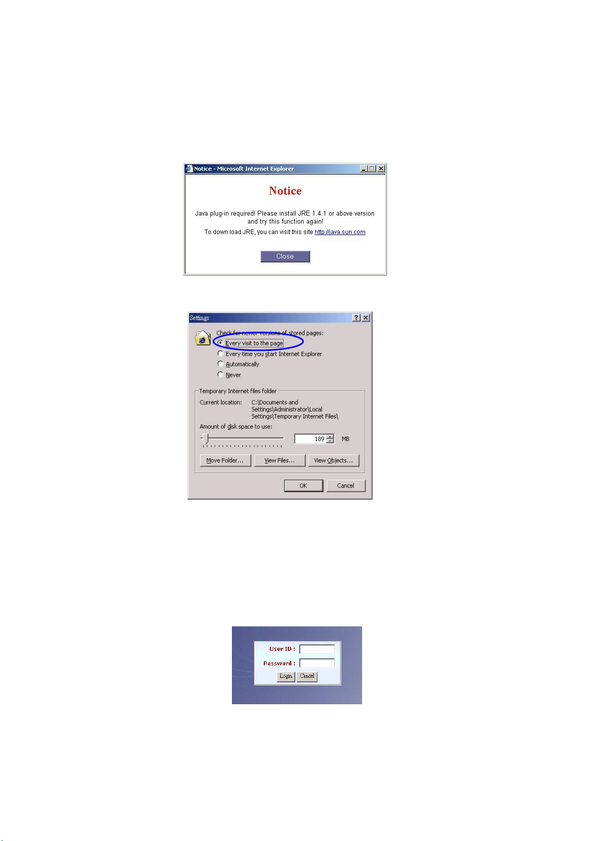
Before you can use the Browser to config SIP IVR, you need to have Java
Standard Runtime (1.4.1.2 (preferred) or later version) to make it work.
You also need to set newer versions of stored pages. Click Tool > Internet
Option > General > Setting.
After success, restart your browser to take effect.
Logon SIPIVR 6800
Setp1: Start IE 6.0 (or later version) to navigate SIP IVR Management System
by typing the default IP address (the default URL is
http://192.168.68.1:10087). The screen will display User ID and
Password as figure 1-1.
Figure 1-1
: The default network IP address is 192.168.68.1 and subnet mask is
255.255.255.0. It is recommended to add the SIPIVR into your trust
host in IE.
7
Page 9
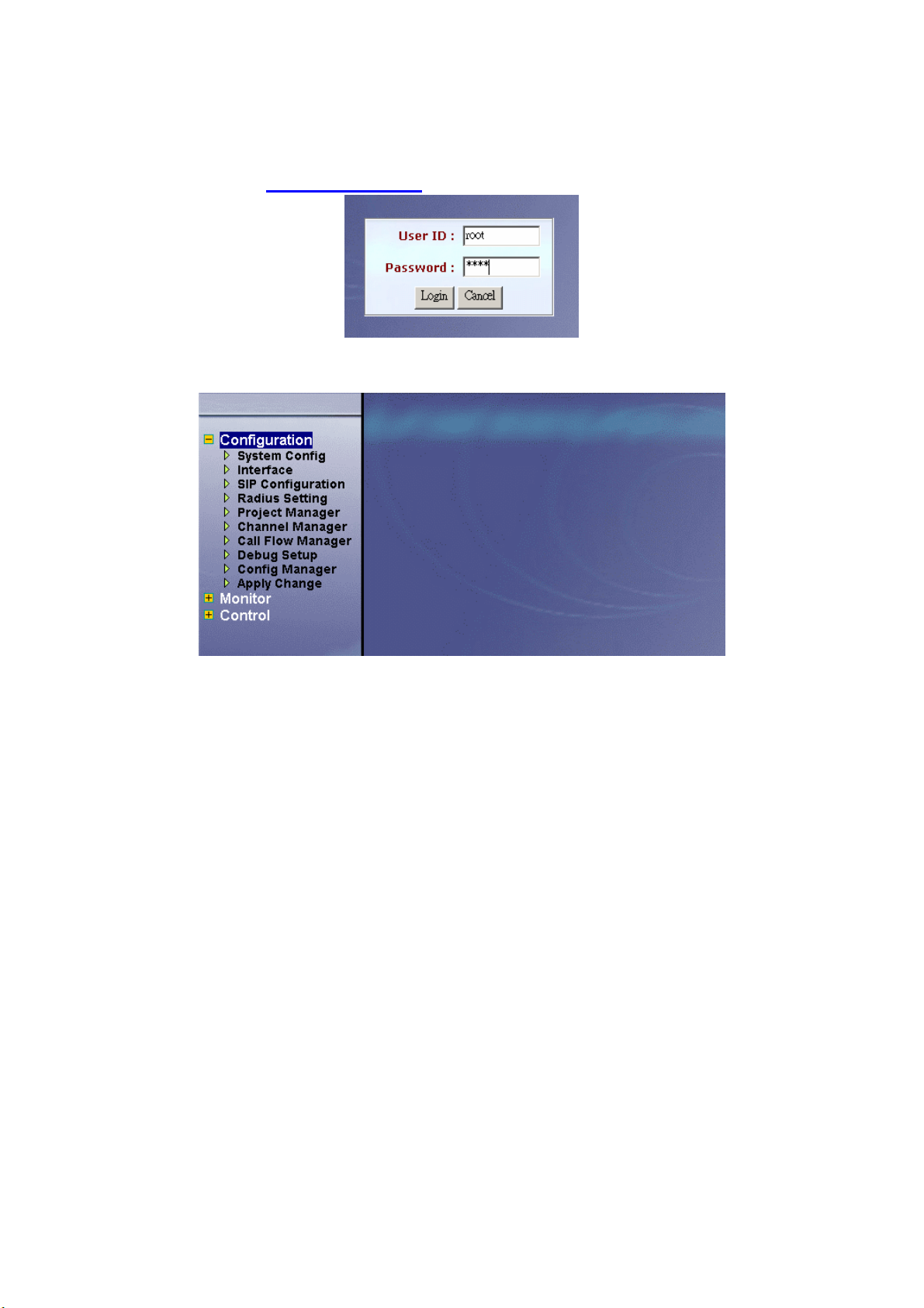
Step 2: Enter log user name and password (the default user ID is root and user
password is root). You can manage your user account via web (refer to
Section “Account Manager”) later.
Figure 1-2
Step 3: The screen shows the Home Page of SIP IVR as figure 1-3.
Figure 1-3
8
Page 10
Chapter 2 Configuration Setting
2.1 Configuration
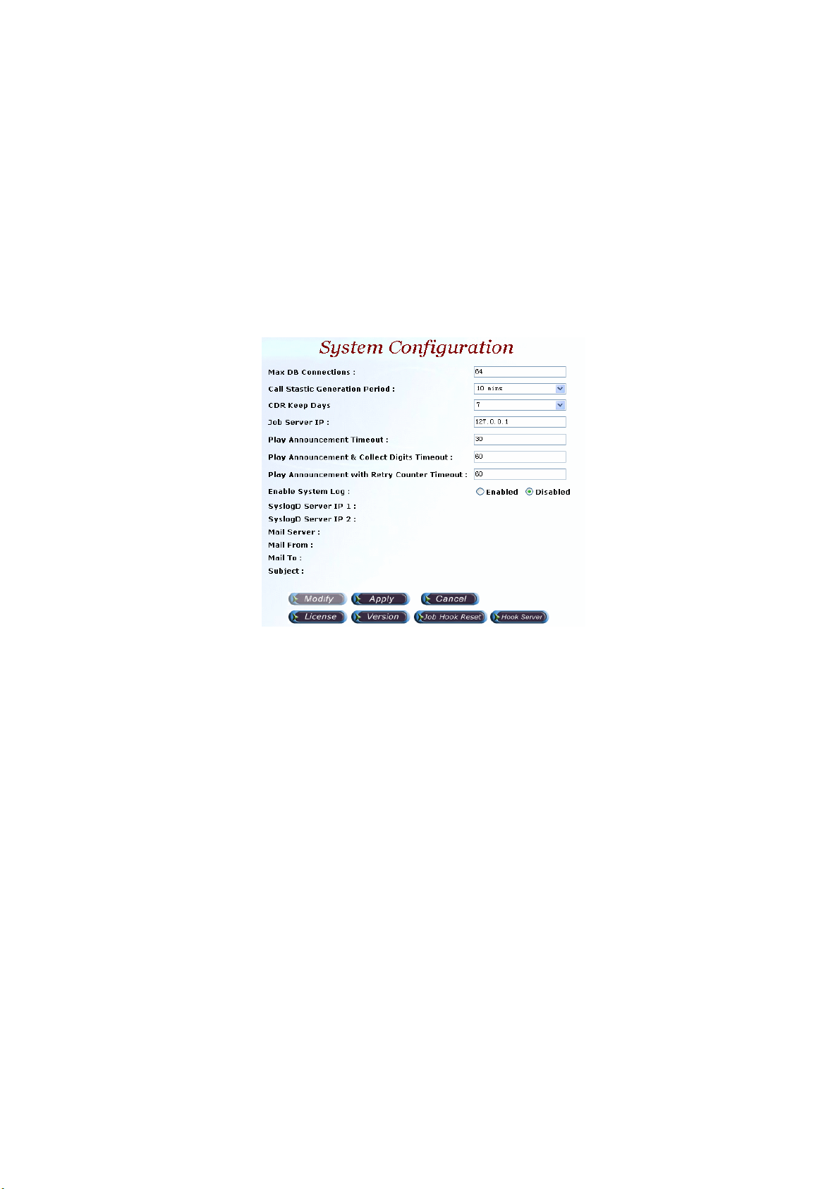
2.1.1 System Configuration
Start Path: Configuration>System Config
Step 1: Click Modify button to setup the System Configuration as figure 2.1-1.
Figure 2.1-1
Description:
• Max DB Connections: Maximum database connection used for managed
connection pool. statistic
• Call Statistic Generation Period: Call statistic record
- None
- 10 mins
- 15 mins
- 30 mins
- 1 hour
- 2 hours
- 4 hours
- 6 hours
- 12 hours
- 1 days
• CDR Keep Days: CDR system keeping days
• Job Server IP:IP address used for Job server
• Play Announcement Timeout: The maximum time to execute for Play
Announcement in seconds
• Play Announcement & Collect Digits Timeout: The maximum time to
execute for Play Announcement & Collect DTMF Digit in seconds
• Play Announcement with Retry Counter Timeout: The maximum times to
execute for retry Play Announcement in second.
9
Page 11
• Enable System Log: Enable to send system information to syslogD
Server or not
• SyslogD Server IP 1,2: syslogd server IP address
• Mail Server: SMTP server host for email notice
• Mail From: Email sender account
• Mail To: Email receiver (semicolon is used for multiple receiver)
• Subject: Email subject to be send to receiver. The following variable
parameters can be used to create dynamic subject for system notice:
- $LOGLEVEL$: Information Level
- $HOSTNAME$: Host name
- $HOSTIP$: Host IP address
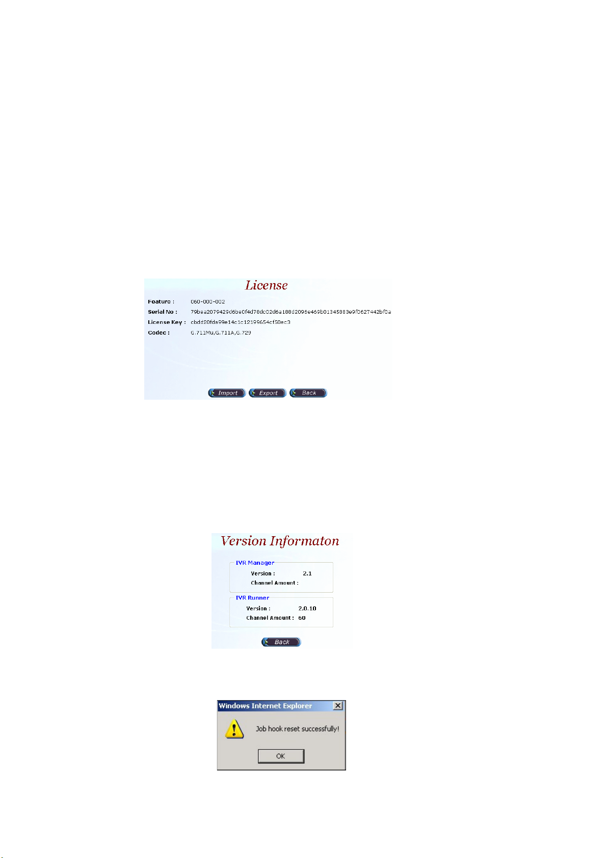
Step 2: Click the License button:
Start Path: Configuration > System Config > License
Figure 2.1-2
License Parameter Description:
• Feature: System parameter
• Serial No: System parameter
• License Key: System parameter
• Codec: The supported codec
☺
Note: Please don’t change it unless under Welltech’s instruction.
Step 3: Click the Version button and you can see the system version:
Figure 2.1-3
Step 4: Click the Job Hook Reset button and you can reset the Job and Hook
service within SIPIVR 6800.
Figure 2.1-4
10
Page 12
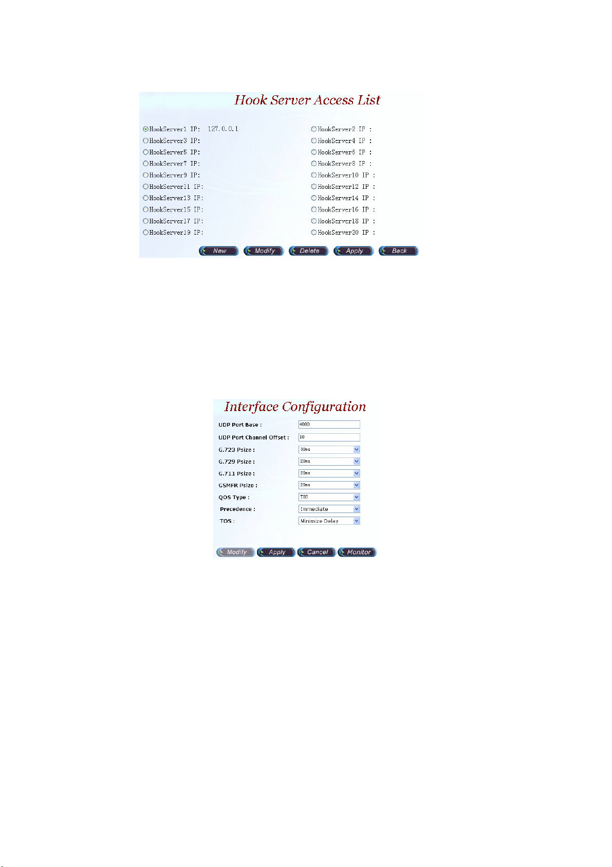
Step 5: Click the Hook Server button:
Figure 2.1-5
Parameter Description:
HookServer IP: Set the hook server IP. You can set up-to 20 hook server IP and
use it in the call flow.
2.1.2 Interface Configuration
Start Path: Configuration> Interface Configuration
Step 1: Click Modify button to setup the Interface Configuration as figure 2.1-6.
Figure 2.1-6
Parameter Description:
• UDP Port Base: UDP port used for RTP stream, each channel needs 3
RTP ports .and must be started by a multiple of 10.
• UDP Port Channel Offset: UDP port used for channel offset.
• G.723 Psize: G.723 transmission packet size (default: 30ms)
• G.729 Psize: G.729 transmission packet size (default: 20ms)
• G.711 Psize: G.711 transmission packet size (default: 20ms)
• GSMFR Psize: GSM transmission packet size (default: 20ms)
• QOS Type: Quality of Service Type
- None: Not using QOS Tag
- DiffServ: Differentiated Services Value
- TOS: Type of Service
• Precedence: Voice package priority setting
- Routine Precedence
- Priority Precedence
11
Page 13
- Immediate Precedence
- Flash Precedence
- Flash Override Precedence
- Critical Precedence
- Internet work Precedence
- Network Precedence
• TOS: Type of Service with the following priority selection.
- Normal Service
- Maximize Reliability
- Maximize Thought
- Minimize Delay
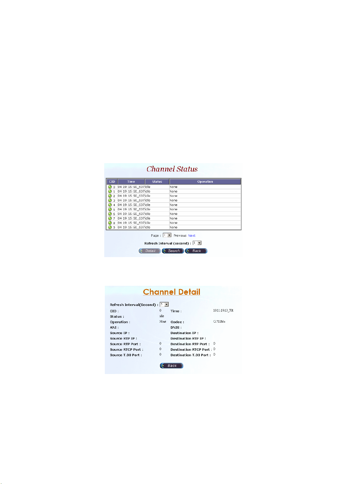
2.1.2.1 Channel Status
Step 3: Click Monitor button, the Channel Status screen displays as figure
2.1-7. After selecting the channel as you need view, click Detail button.
Figure 2.1-7
Step 4: The Channel Detail screen displays as figure 2.1-8, click the Back
button to back the Channel Status screen.
Figure 2.1-8
Description:
• Refresh Interval (Second): Refresh interval time (1, 5, 10 seconds).
• CID: Channel ID.
• Time: Updated status time.
• Status: Channel Status.
• Operation: Current operation is running for the interface.
• Codec: Current codec.
12
Page 14

• ANI: Calling number.
• DNIS: Called number.
• Source IP: Source IP Address.
• Destination IP: Destination IP Address.
• Source RTP IP: Source RTP IP.
• Source RTP Port: Source RTP Port.
• Source RTCP Port: Source RTCP Port.
• Source T.38 Port: Source T.38 Port.
• Destination RTP IP: Destination RTP IP.
• Destination RTP Port: Destination RTP Port.
• Destination RTCP Port: Destination RTCP Port.
• Destination T.38 Port: Destination T.38 Port.
2.1.3 SIP Configuration
Start Path: Configuration>SIP Configuration
Step 1: Click Modify button to setup the SIP Configuration as figure 2.1-9.
Figure 2.1-9
Description:
• Register Server: SIP register proxy server IP Address.
• Register Port: SIP register proxy server port number (default: 1719).
• Register User: SIP register proxy server User ID.
• Register Password: SIP register proxy server User Password.
• Register TTL: The maximum time to live setting when registered to the SIP
proxy server.
• Domain Name: SIP Proxy Server domain name. It’s normally used when
you have a DNS record setup for SIPIVR 6800.
• Outbound Proxy Server: The IP address of an outbound Proxy.
• Outbound Proxy Port: The port of an outbound Proxy.
• Outbound Proxy User: The User ID of an outbound Proxy.
• Outbound Proxy Password: The password of an outbound Proxy.
• Local Codec 1~5: Codec selection priority (1 to 5) (1: highest, 5: lowest).
13
Page 15
• DTMF Relay Method: DTMF transport type selection.
- SIP INFO
- Transparent
- RFC2833
• RFC2833 Payload Type: RTP payload type used for RFC2833 DTMF
relay.
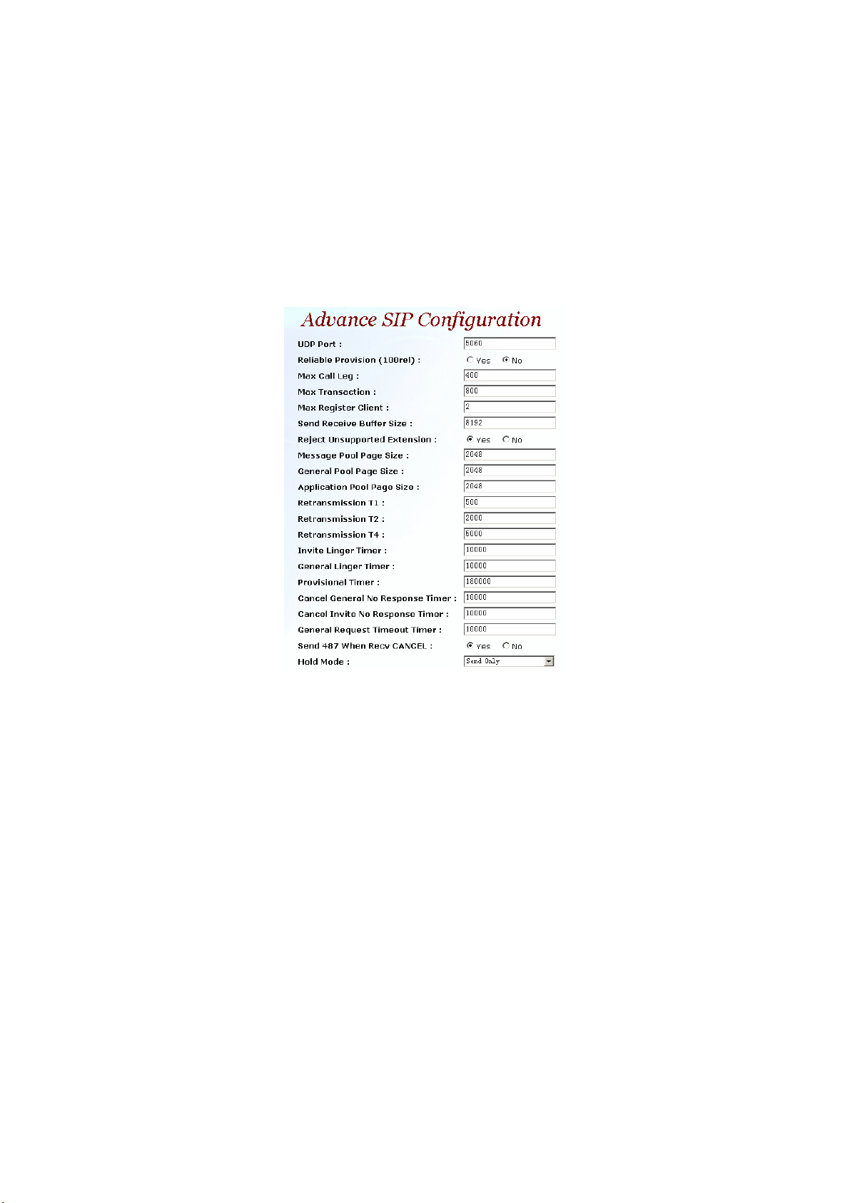
2.1.3.1 Advance SIP Configuration
Step 3: Click Advance button, you can setup the Advance SIP Configuration
and the Advance SIP Configuration screen displays as figure 2.1-10.
Figure 2.1-10
Parameter Description:
• UDP Port: The local UDP port on which the SIP Stack listens.
• Reliable Provision (100rel):Requited PRACK or not (100rel)
• Max Call Leg: The maximum number of call-legs the SIP Stack allocates.
You should set this value to the maximum number of call you expect the
SIP Stack to handle simultaneously.
• Max Transaction: The maximum number of transactions the SIP Stack
allocates. You should set this value to the maximum number of call you
expect the SIP Stack to handle simultaneously.
• Max Register Client: The maximum number of Register-Clients the SIP
Stack allocates. You should set this value to the maximum number of call
you expect the SIP Stack to handle simultaneously.
• Send Receive Buffer Size: Set the size of message buffer. The buffer used
by SIP Stack for receiving and sending SIP messages.
• Reject Unsupported Extension: Yes or No
• Message Pool Page Size: Used to hold and process all incoming and
outgoing message in the form of encoded messages or message objects.
It is recommended that you configure the page size to the average
message size your system is expected to message.
• General Pool Page Size: Used by SIP Stack objects, such as call-legs and
14
Page 16

transaction, to store the internal fields. For example, the call-legs object
will store the To, From and Call-ID headers and the local and the remote
contact addresses on the general pool pages. The general pool is also
used from other activities that demand memory allocation.
• Application Pool Page Size: The size of page in the application pool.
• Retransmission T1:T1 determines several timers as defined in RFC3261.
For example, when an unreliable transport protocol is used, a Client Invite
transaction retransmits requests at an interval that start at T1 seconds and
doubles after every retransmission. A Client General transaction
retransmits requests at an interval that starts at T1 and doubles until it
reaches T2. (Default Value: 500)
• Retransmission T2: Determines the maximum retransmission interval as
defined in RFC3261. For example, when an unreliable transport protocol
is used, general requests are retransmitted at an interval which starts at
T1 and doubles until reaches T2. If a provisional response is received,
retransmission continue but at an interval of T2. (Default Value: 4000)
• Retransmission T4:T4 represents the amount of time the network takes to
clear message between client and server transactions as defined in
RFC3261. For example, when working with an unreliable transport
protocol, T4 determines the time that UAS waits after receiving an ACK
message and before terminating the transaction. (Default Value: 5000)
• Invite Linger Timer: After sending an ACK for an INVITE final response, a
client cannot be sure that the server has received the ACK message; the
client should be able to retransmit the ACK upon receiving retransmissions
of the final response for invite Linger Timer milliseconds.
• General Linger Timer: After a server sends a final response, the server
cannot be sure that the client has received the response message. The
server should be able to retransmit the response upon receiving
retransmissions of the request for general Linger Timer milliseconds.
(Default Value: 32000)
• Provisional Timer: When a client receives a provisional response, it
continues to retransmit the request, but with an interval of provisional
Timer milliseconds.
• Cancel General No Response Timer: When sending a CANCEL request
on a General transaction, the User Agent waits cancel General No
Response Timer milliseconds before timeout termination if there is no
response for the cancelled transaction.
• Cancel Invite No Response Timer: When sending a CANCEL request on a
Invite transaction, the User Agent waits cancel Invite No Response Timer
milliseconds before timeout termination if there is no response for the
cancelled transaction.
• General Request Timeout Timer: After sending a General request, the
User Agent waits for a final response general Request Timeout Timer
milliseconds before timeout termination (in this time the User Agent
retransmits the request every T1, 2*T1,…T2,…milliseconds)
• Send 487 When Recv CANCEL: When receive CANCEL form remote site,
send “487 Request canceled” or not
• Hold Mode: The SIP hold message mode.
- Send Only: SDP Media Attribute will be set Send Only when send
15
Page 17
re-invite out.
- 0.0.0.0: SDP Media Attribute will be set 0.0.0.0 when send re-invite out.
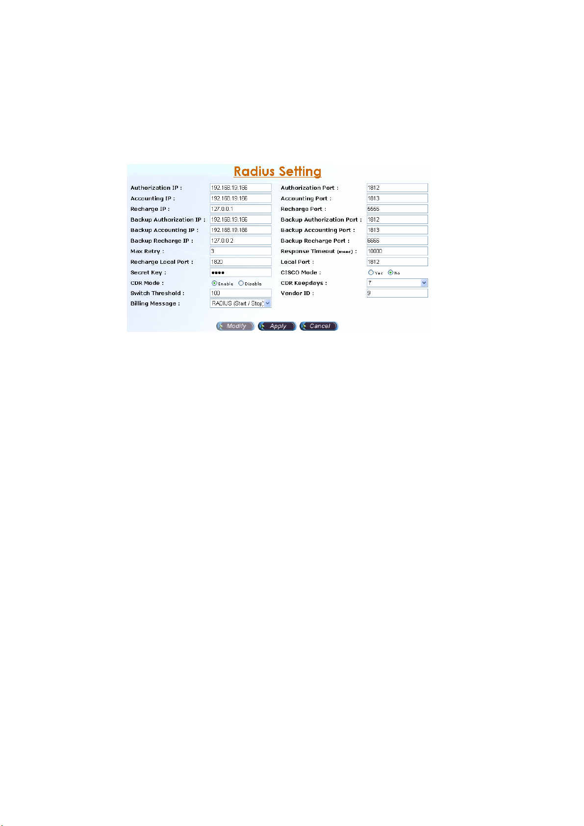
2.1.4 Radius Setting
Start Path: Configuration>Radius Setting
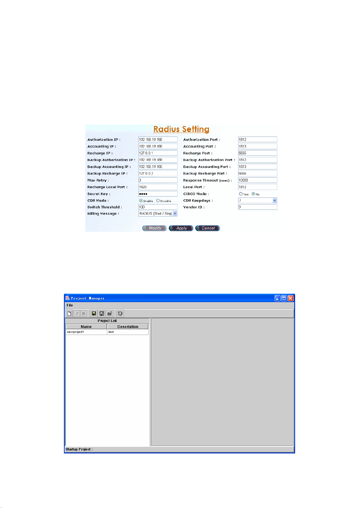
Step 1: Click Modify button to setup the Radius Setting as figure 2.1-11.
Figure 2.1-11
Parameter Description:
• Authorization IP: RADIUS Authentication/Authorization server IP address
• Authorization Port: RADIUS Authentication/Authorization server Port
• Accounting IP: RADIUS Account server IP address.
• Accounting Port: RADIUS Account server Port.
• Recharge IP: RADIUS recharge server IP address (Welltech 6600 is
required for recharging service)
• Recharge Port : RADIUS recharge server port.
• Backup Authorization IP: Backup RADIUS Authentication/Authorization
server IP address.
• Backup Authorization Port: Backup RADIUS Authentication/Authorization
server Port.
• Backup Accounting IP: Backup RADIUS Account server IP address.
• Backup Accounting Port: Backup RADIUS Account server Port.
• Backup Recharge IP: RADIUS Recharge server IP address.
• Backup Recharge Port : RADIUS Recharge server port.
• Max Retry: The maximum retry times.
• Response Timeout (msec): The maximum wait for response time from
RADIUS server.
• Recharge Local Port: The RADIUS client local port for recharge service
(Welltech 6600 is required for recharge).
• Local Port : The RADIUS client local port for Authentication, Authorization
and Accounting (default is 1812)
• Secret Key: The shared secret key with RADIUS server.
• CISCO Mode: Send redundant RADIUS attribute as CISCO mode or not.
• CDR Mode: Enable write the CDR or not
• CDR Keepdays: CDR system keeping days
• Switch Threshold: Switch to alternate RADIUS server when failures are
occurred more than switch threshold.
16
Page 18
• Vendor ID: RADIUS Vendor ID
• Billing Message: The message type for billing.
- None: Not to send RADIUS accounting message out
- RADIUS (Start / Stop): Log CDR into the file and send RADIUS
start/stop billing message out.
- RADIUS (Stop): Log CDR into the file and send RADIUS stop billing
message out.
Step 2: After changing the parameters and apply the change by clicking Apply
button as figure 2.1-12.
Figure 2.1-12
2.1.5 Project Manager
Start Path: Configuration>Project Manager
Step 1: Click Configuration> Project Manager, the screen will display as
figure 2.1-13.
Figure 2.1-13
17
Page 19
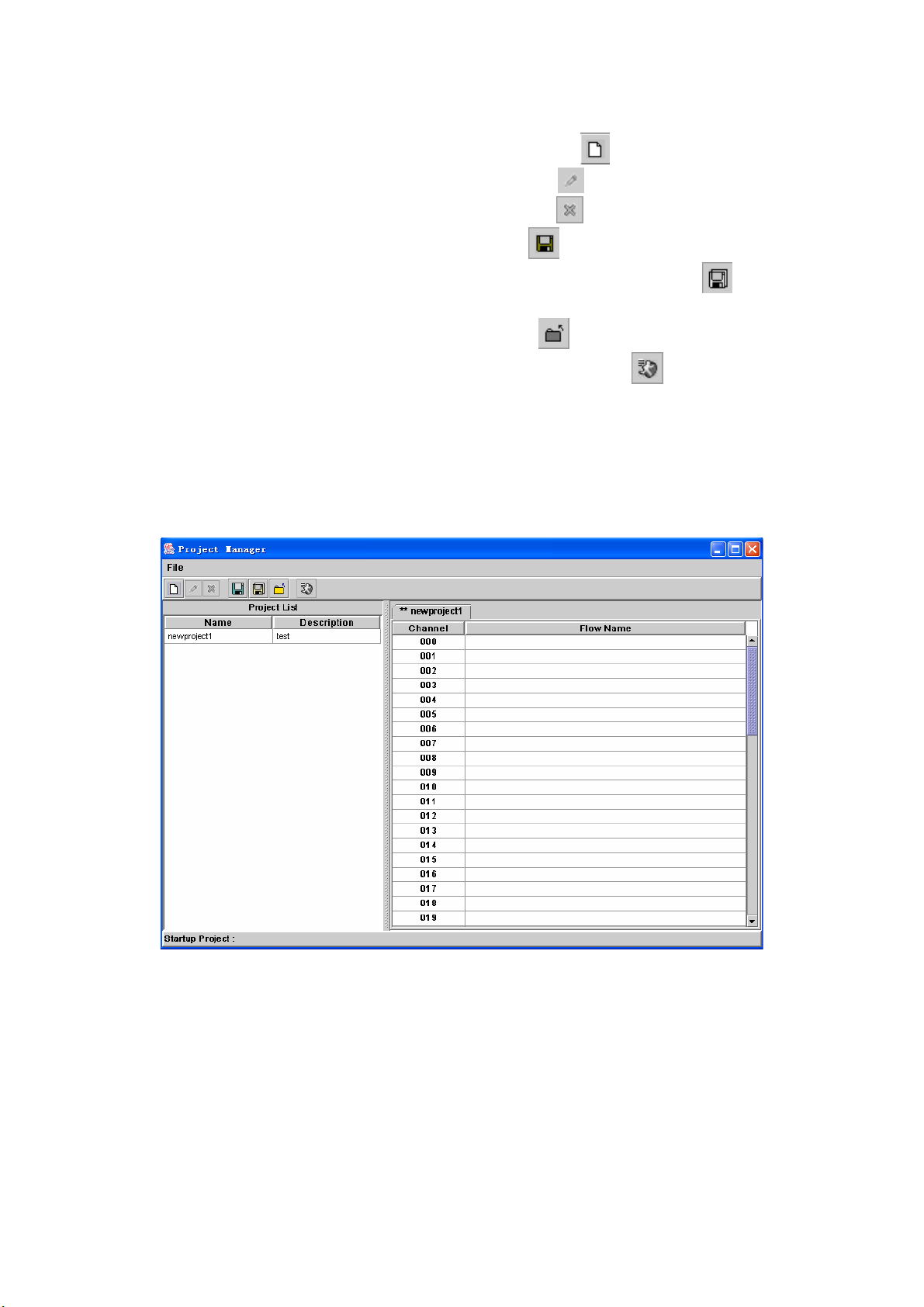
Menu and Toolbar Description:
• New Project: Creating a new project ( Or click the icon in the toolbar )
• Modify Project: Modify the project ( Or click the icon in the toolbar )
• Delete Project: Delete the project ( Or click the icon in the toolbar )
• Save Project: Save the project (Or click the icon in the toolbar )
• Save Project as: To save the project to a new name (Or click the icon
in the toolbar )
• Close Project: Close the project (Or click the icon in the toolbar )
• Set Startup Project: Set the start-up project (Or click the
icon in the
toolbar). The SIP IVR will automatically run the start-up project when system
is started.
• Exit: Quit the system.
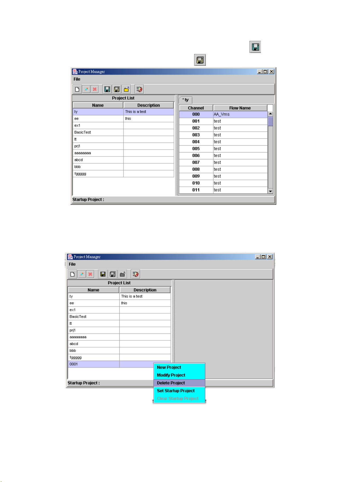
《New Project》
Step 2: Click File>New Project (Or right click anyone project and select New
Project), the new project section will display as figure 2.1-14.
Figure 2.1-14
Step 3: Right click the blank channel and select Select Call Flow as figure
2.1-15.
18
Page 20
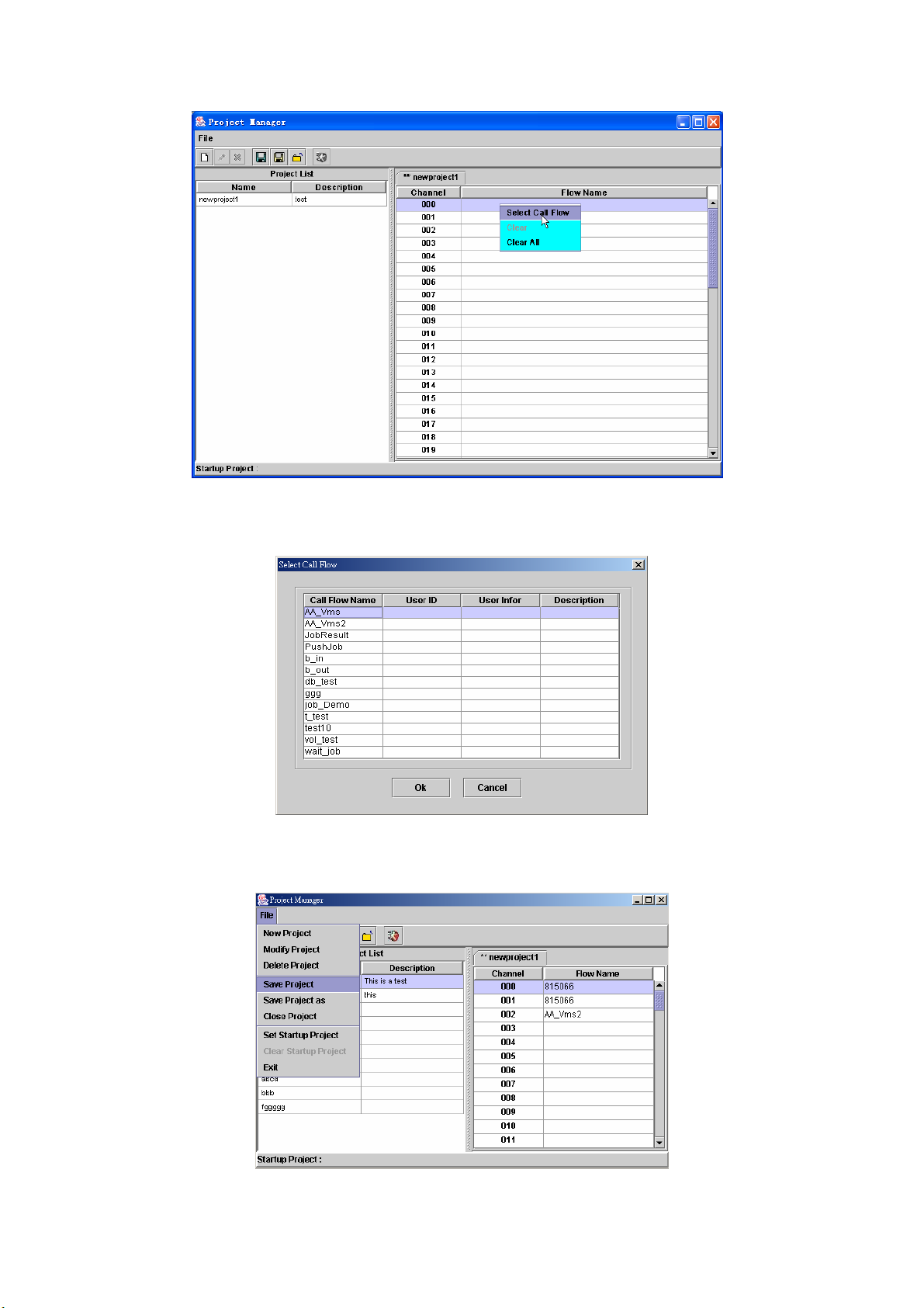
Figure 2.1-15
Step 4: The screen display the Select Call Flow as figure 2.1-16. Choose the
call flow to be used and click on Ok button.
Figure 2.1-16
Step 5: After selected the call flow for a project, click File>Save Project to save
the project as figure 2.1-17.
Figure 2.1-17
19
Page 21
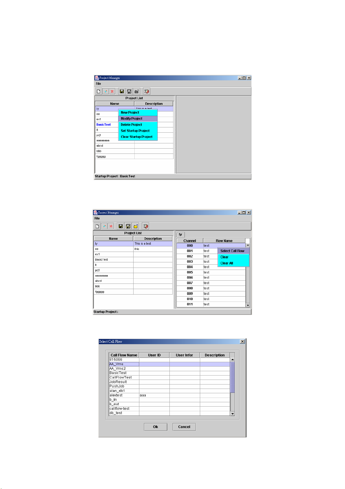
《Modify Project》
Step 6: Choose the project to be modified and click File>Modify Project (Or
right click the project and select Modify Project), the project section will
display as figure 2.1-18.
Figure 2.1-18
Step 7: Right click the channel to be modified and select Select Call Flow as
figure 2.1-19.
Figure 2.1-19
Step 8: Choose the call flow to be used and click Ok button.
Figure 2.1-20
20
Page 22
Step 9: After change the project and save the change by clicking button.
Save the file to a new name can be use button.
Figure 2.1-21
《Delete Project》
Step 10: Choose the project to be deleted and click File>Delete Project (Or
right click the project and select Delete Project), the project section will
display as figure 2.1-22.
Figure 2.1-22
Step 11: Display the screen show “Are you sure to delete selected
projects?” click OK button to delete call flow as figure 2.1-23.
21
Page 23
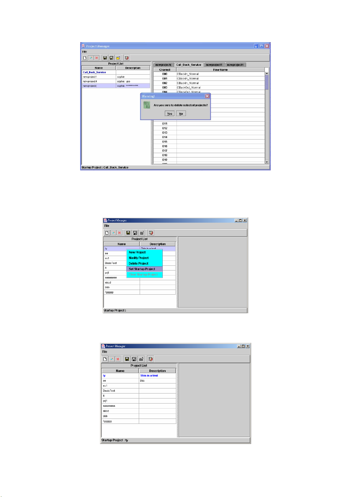
Figure 2.1-23
《Set Startup Project》
Step 12: To automatically run a saved project when system is started, choose
the project and click File>Set Startup Project (Or right click the project
and select Set Startup Project). Only one start-up project can be set.
Figure 2.1-24
Step 13: When a project is set to be a start-up project, the start-up project
name is displayed as bold font in blue color.
Figure 2.1-25
22
Page 24

《Clear Startup Project》
Step 14: To clean the start-up project setting, choose the project and click
File>Clear Startup Project (Or right click the project and select Clear
Startup Project), the section will display as figure 2.1-26.
Figure 2.1-26
2.1.6 Call flow Manager
Start Path: Configuration>Call flow Manager
《New Call Flow》
Step 1: Click New button to add a new call flow as figure 2.1-27.
Figure 2.1-27
Step 2: The new call flow screen will display as figure 2.1-28. (Please refer to
section “Call Flow Menus and Tools”)
23
Page 25
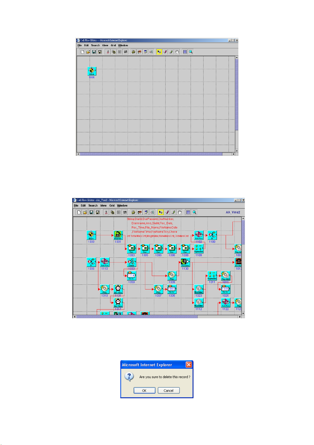
Figure 2.1-28
《Modify Call Flow》
Step 3: Select the call flow to be modified, and click Modify button as figure.
The call flow screen will display as figure 2.1-29. (Please refer to
section “Call flow Menus and Tools”)
Figure 2.1-29
《Delete Call Flow》
Step 4: If you want to delete an existing flow, select the call flow name to be
deleted and click Delete button. When screen shows “Are you sure to
delete this record?” click OK button as figure 2.1-30.
Figure 2.1-30
24
Page 26
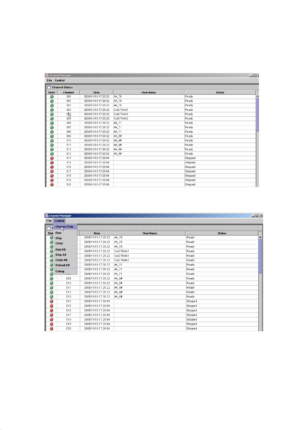
2.1.7 Channel Manager
Start Path: Configuration>Channel Manager
Step 1: Click Configuration>Channel Manager, the channel manager screen
will display as figure 2.1-31.
Figure 2.1-31
Step 2: To change or set a call flow into a running channel, click Run>Choose
Flow as figure 2.1-32. Or right click the blank channel and select Load.
Figure 2.1-32
Step 3: The screen display the Call Flow as figure 2.1-33. Choose the call flow
to be used and click Ok button.
25
Page 27
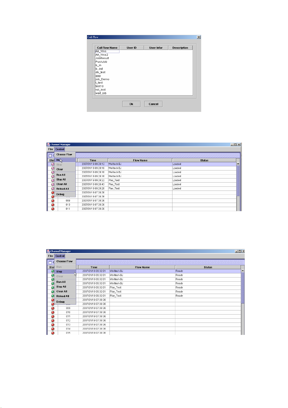
Figure 2.1-33
Step 4: After selected the call flow for a channel, click Control>Run as figure
2.1-34 (Or right click the channel and select Run.) to start the call flow.
Run all can use Control>Run All.
Figure 2.1-34
Step 5: To stop / pause the running call flow, click Control>Stop or Pause as
figure 2.1-35 for a selected channel ( or right click the channel and select
Stop / Pause for a selected channel ).Stop all or pause all can be used
for all channels by click Control>Run All or Control>Pause All.
Figure 2.1-35
Step 6: To clear the running call flow, click Control>Clear for a selected
channel as figure 2.1-36 (Or right click the channel and select Clear).
Clear all can be used to clear all channels by click Control>Clear All.
26
Page 28
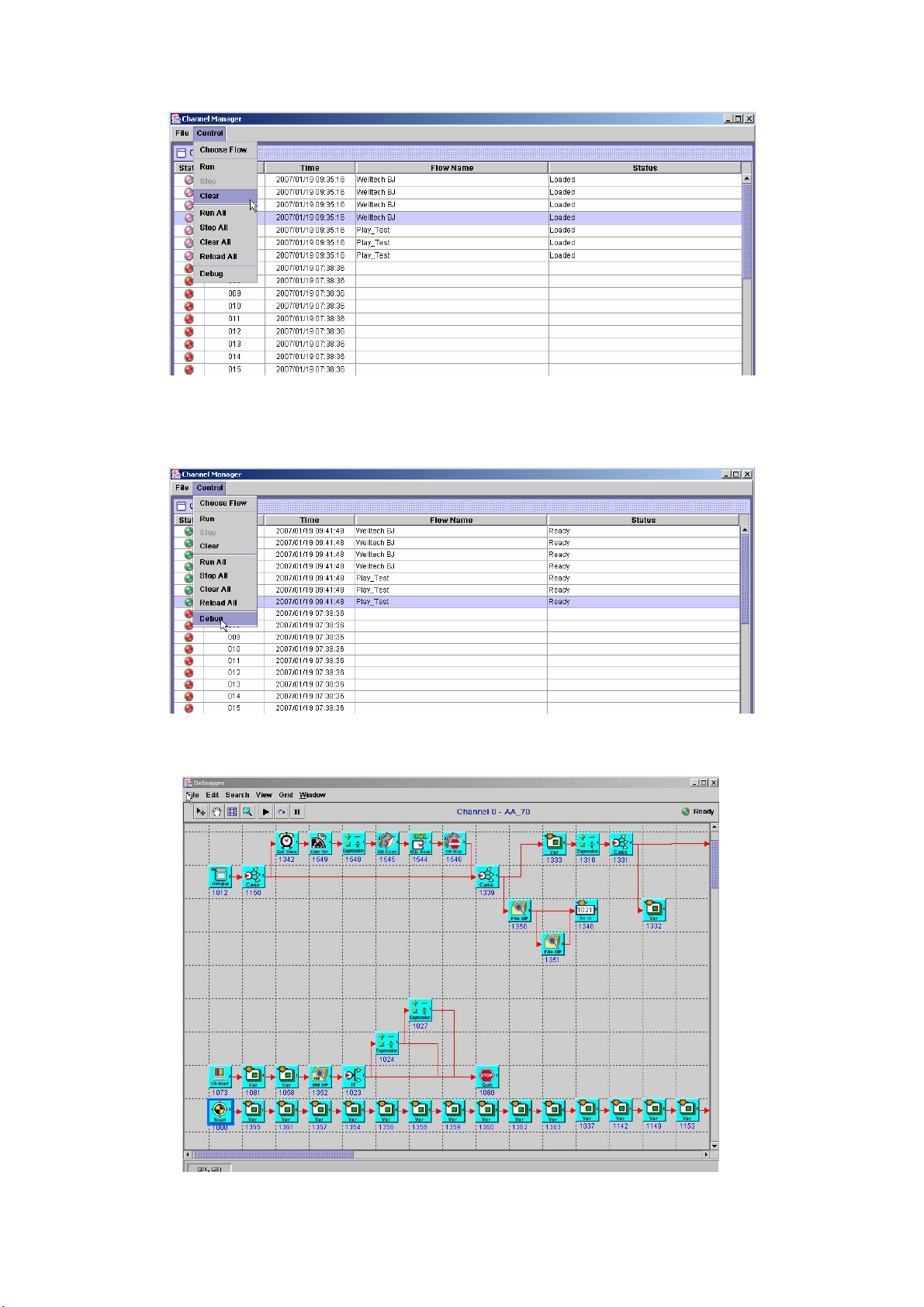
Figure 2.1-36
《Debug Mode》
Step7: When the call flow is running, you can use graphic debugger to debug
or trace. Click Control>Debug as figure 2.1-37.
Figure 2.1-37
Step8: The Call Flow Debugger screen displayed as figure 2.1-38.
Figure 2.1-38
27
Page 29
Menu Description:
• File Menu
Load Sub Flow: Load the flow that belonged to this flow.
Exit: Quit the system
• Edit Menu
Run: Start to execute the call flow for the debug channel.
Step: This function is used to step by step execute a component at once.
Pause: Pause the call flow
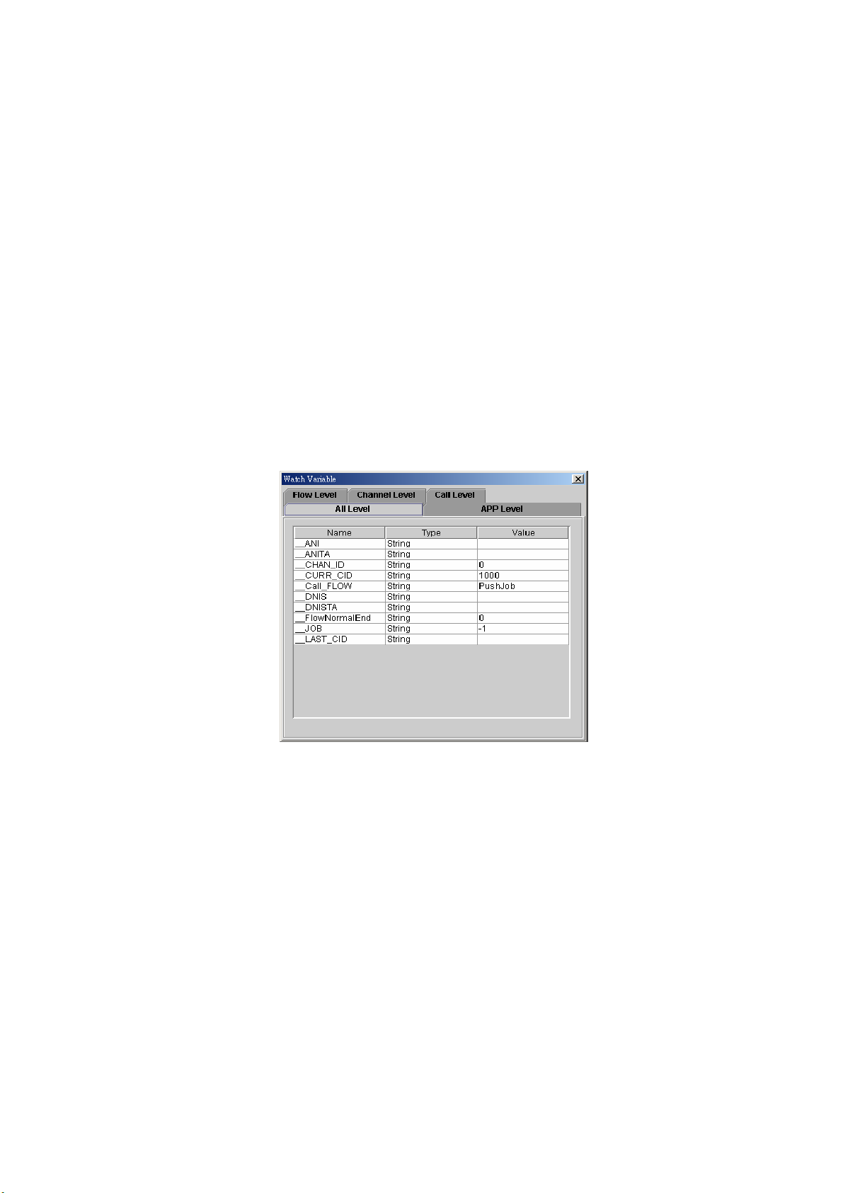
Edit/Watch Variable:
Select Edit/Watch Variable from the Edit menu and Watch Vari able
screen will display as figure 2.1-39. This function is used to view or
modify the system variable.
All Level: All variable include system. Application call flow channel
and channel and call level variables.
APP Level: Application level variables.
Flow Level: Call flow level variables.
Channel Level: Channel level variables.
Call Level: Call level variables.
Figure 2.1-39
Snap to Grid: Automatically align the icon with grid line or not.
Clear Message: Clear message.
• Search Menu
The "Search" pull down menu includes these functions:
Find: Search component by component ID or component type.
• View
Zoom: Zoom in and zoom out to make your call flow diagram larger or
smaller.
View Grid: Toggle on/off the gridlines.
Debug Message: Display the debug information.
• Grid
Set the grid size.
• Window
Jump between opened call flows by selecting another call flow from the
menu.
28
Page 30
Tool bar Description:
• :Start on the call flow
• :After put the Break Point in the call flow, this function is used to step by
step execute the call flow
• :Pause the call flow
:Scroll upwards and downward in the windows to view the complete call
•
flow
•
:Select component
:Toggle on/off the gridlines
•
•
: Zoom in or zoom out the workspace
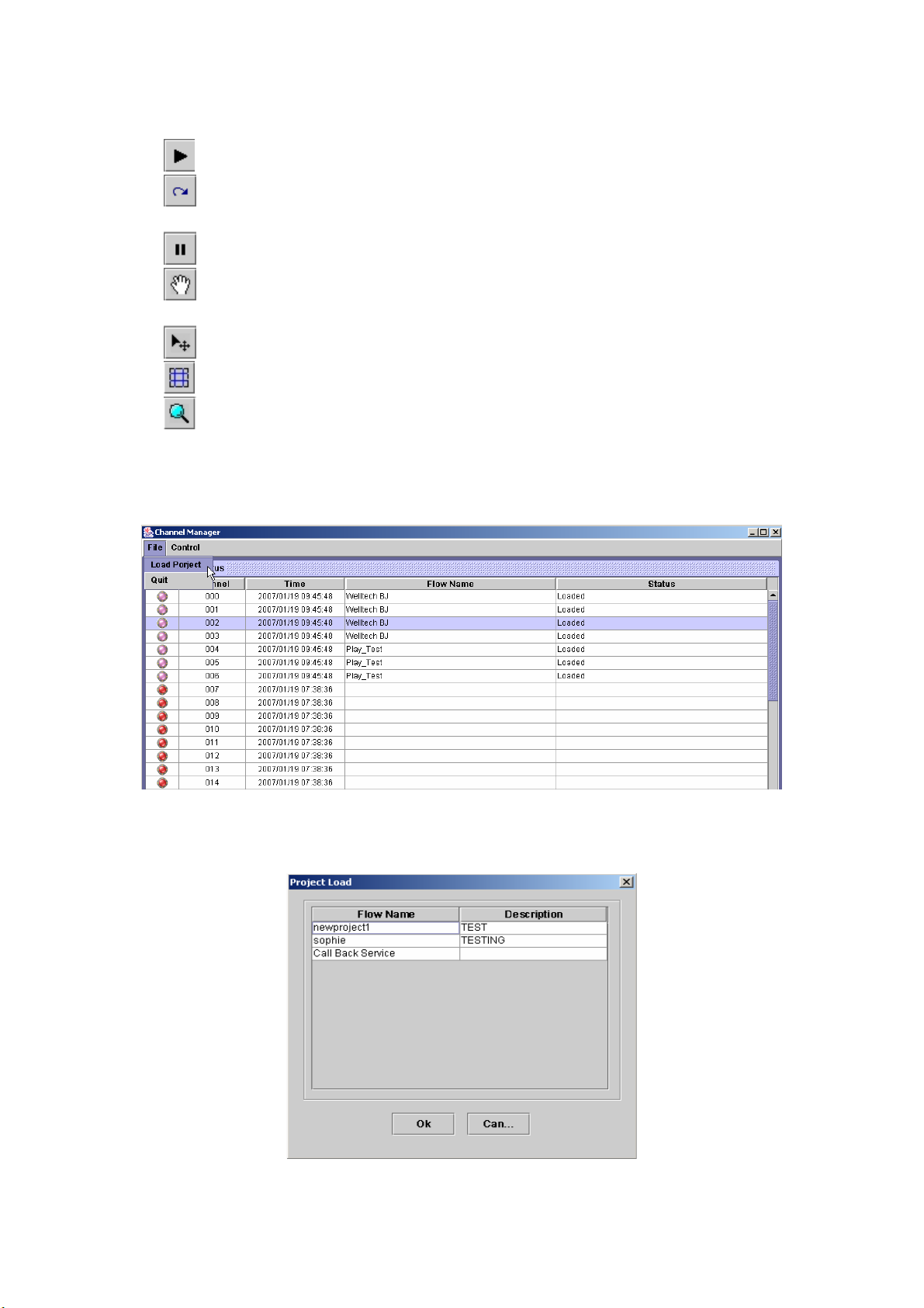
《Load Project》
Step9: Load Project provides a workspace to store channel and call flow
mapping for easy to run (click File>Load Project) as figure 2.1-40.
Figure 2.1-40
Step10: The Project Load screen displayed as figure 2.1-41. Choose the
project to be loaded and click Ok button.
Figure 2.1-41
29
Page 31

Step11: The project is successfully loaded as figure 2.1-42.
Figure 2.1-42
2.1.8 Debug Setup
Debug can be turn on or off based on each system module and level to
minimum the debug information. Please only turn on the debug information
for debug purpose under Welltech FAE's instruction and turn off when
complete. Or the system performance will be greatly hit.
Start Path: Configuration > Debug Setup
Figure 2.1-43
2.1.9 Config Manager
Configuration Management provides a way to save and reload the
system configuration for future use.
Load a Configuration:
Step 1: When you need to load a saved configuration, click a saved
configuration (i.e. 12/15/2006 50:52 AM Rod20060427) item to load it
back as figure 2.1-44.
30
Page 32
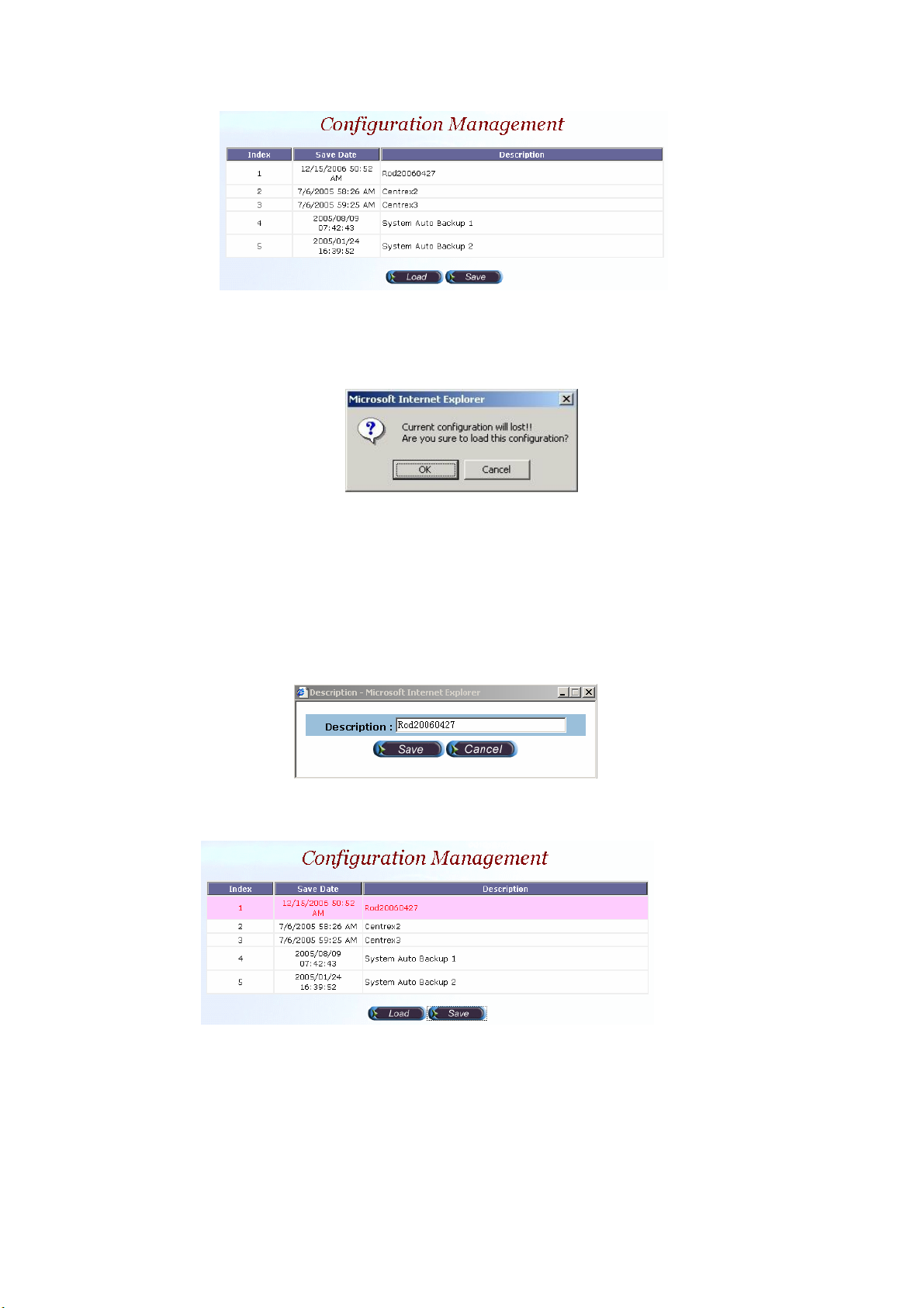
Figure 2.1-44
Step 2: When screen shows “Current configuration will lost! Are you sure
to load this configuration?” click OK button to load the saved
configuration to the working configuration as figure 2.1-45.
Figure 2.1-45
☺Note: It need restart the system to take effect of the new-loaded working
configuration.
Save the working Configuration:
Step 3: To save the current configuration, select a new created configuration
and click Save button, when screen shows “Description”, please enter
the configuration description (i.e. Rod20060427) for the saved
configuration as figure 2.1-46.
Figure 2.1-46
Step 4: You can see the screen display the changes as figure 2.1-47.
Figure 2.1-47
2.1.10 Apply Change
1. Some of modification needs to restart system before it is effective to system
operation. For the modification can be changed to fly, “Apply the Change”
shows “Are you sure to apply the running system?” Click OK button to
take effect.
31
Page 33
2.2 Monitor
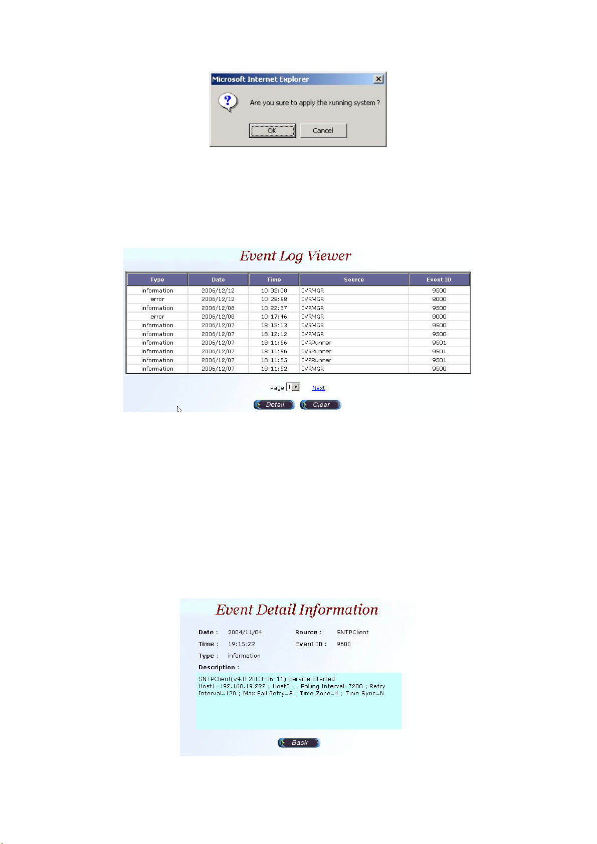
2.2.1 Event Log
Start Path: Monitor>Event Log
Field Description:
Figure 2.1-48
Figure 2.2-1
• Type: Event Log type
- Information
- Warring
- Error
• Date: Event created date
• Time: Event created time
• Source: Executable program
• Event ID: Event Log
Step 1: Double click the log or select the log and click detail to see the log
detail.
Figure 2.2-2
32
Page 34
Event Description:
Event ID
Error
Information
Event Description
8000
8000
8000
8001
8001
8001 RUNNER: System error
8001 RUNNER: Invalid project
8001
9500
9500
9500
9500
9501
9501
9501
IVRMGR Can not find the interface
IVRMGR Interface error
IVRMGR Failed to Register to Sip proxy
RUNNER: Failed to Load License, please
contact technical support
RUNNER: License error, please contact
technical support
RUNNER: Failed to load call flow
IVRMGR Service Started
IVRMGR Interface Service Started
IVRMGR Sip Service Started
IVRMGR Sip proxy Registered
RUNNER: Service Started
RUNNER: Start Up Project loaded and run
RUNNER: Project loaded and run
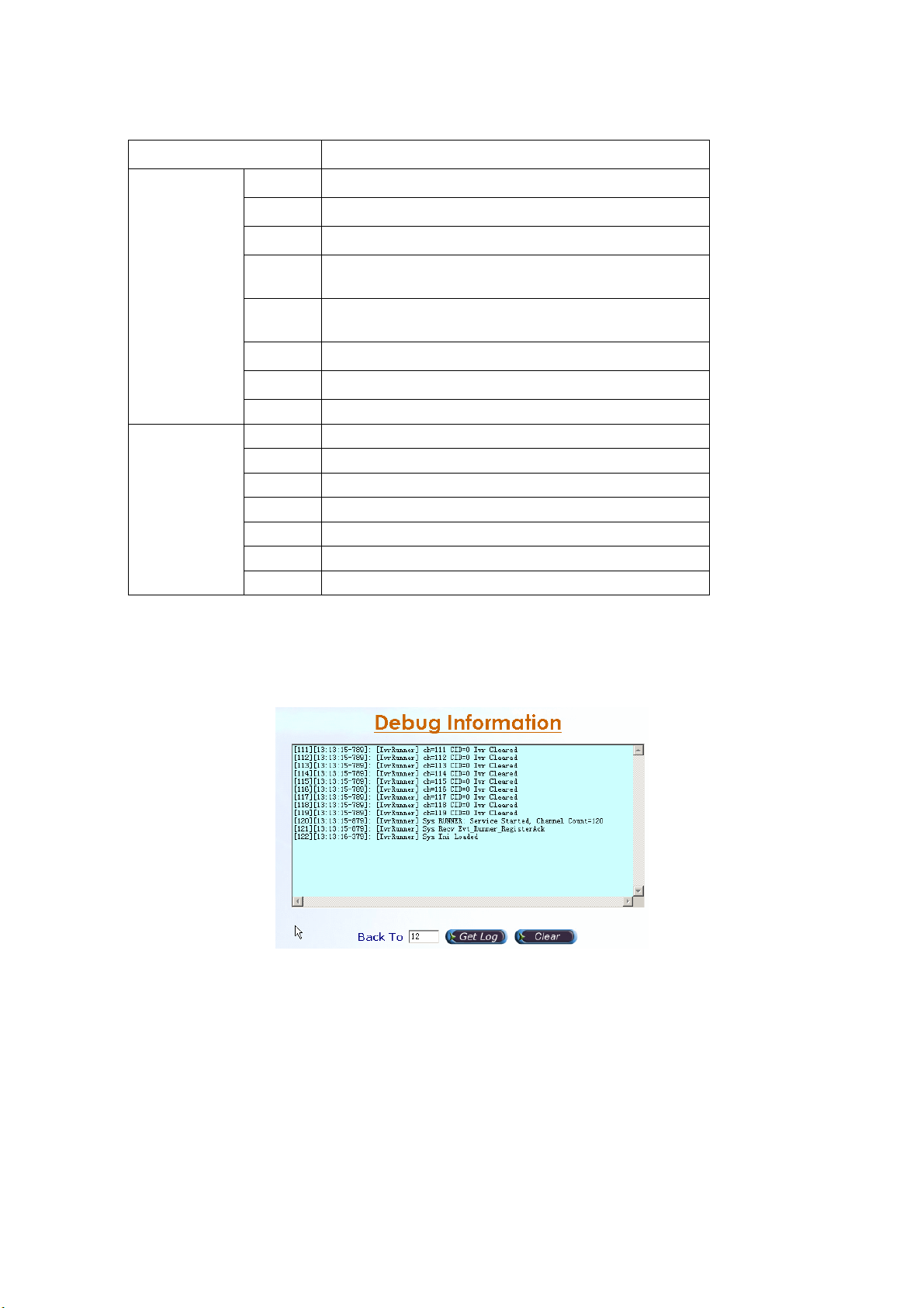
2.2.2 Debug Information
Start Path: Click “Monitor>Debug Info”
Figure 2.2-3
Filed Description:
• Get Log: Get previous debug log (0 for none) by Back To field
• Clear: Clear log
2.2.3 Ping
Start Path: Configuration>Ping
Step 1: You can use the Ping to check an IP is active or not. Enter Target IP or
Host Name and click Ping button as figure 2.2-4.
33
Page 35
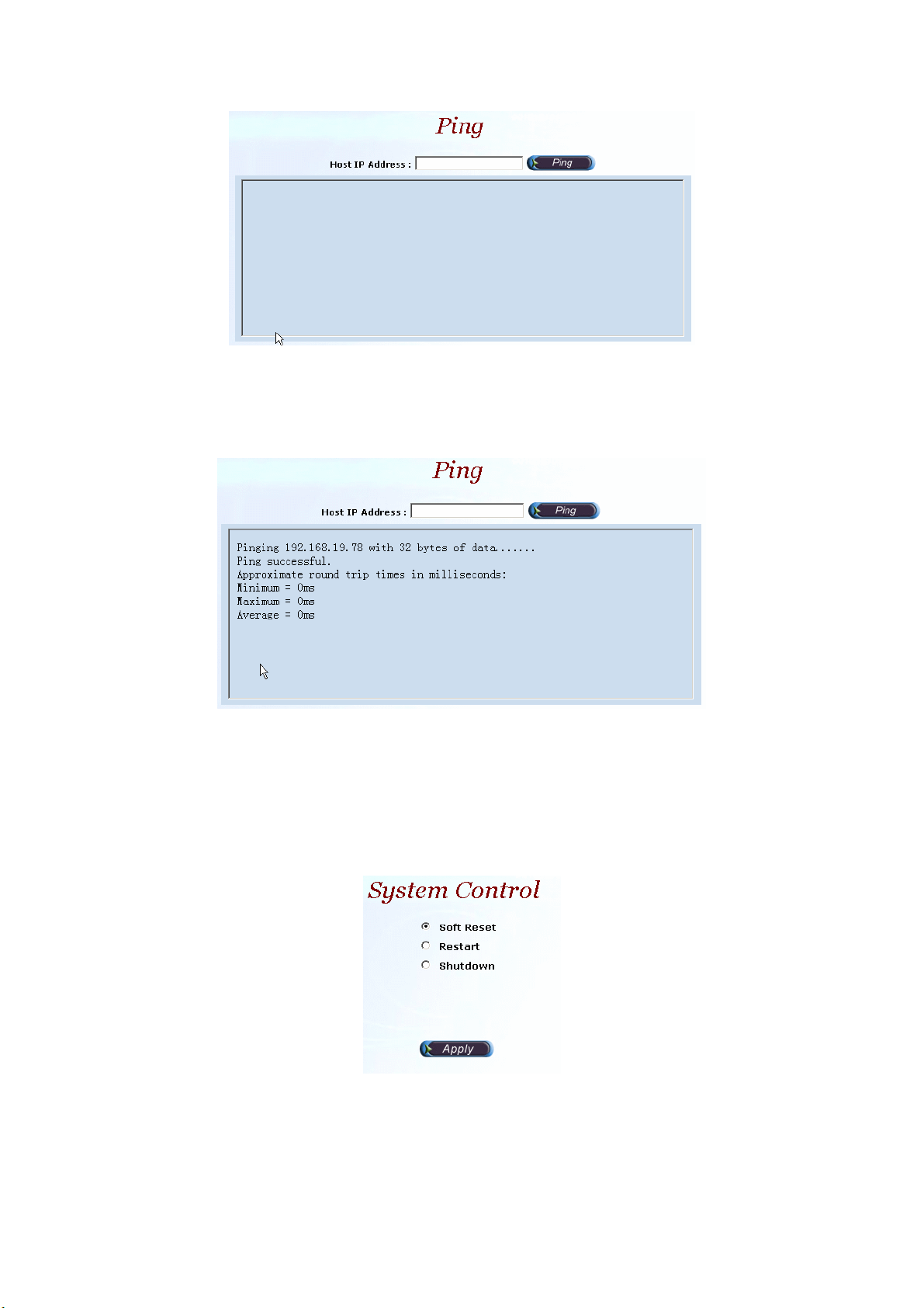
Figure 2.2-4
Field Description:
• Host IP Address: The IP address to ping
Step 2: The screen will show the ping information as figure 2.2-5.
Figure 2.2-5
2.3 Control
2.3.1 System
Start path: Click Control>System
Figure 2.3-1
Parameter:
• Soft Reset: Soft Reset the system
• Restart: Restart the system
• Shutdown: Shutdown the system
34
Page 36
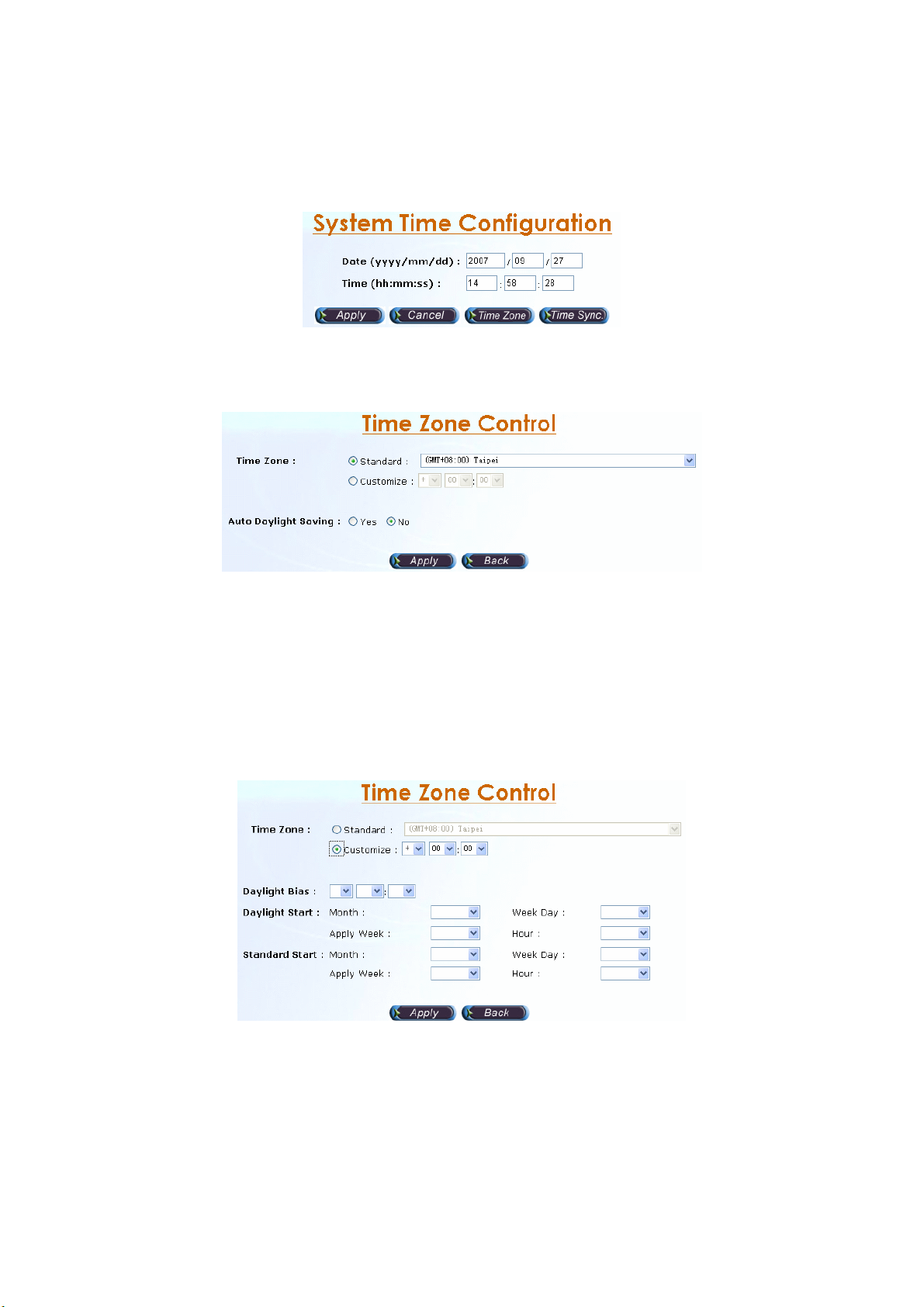
2.3.2 System Time
2.3.2.1 Time Zone Setting
Step 1: Click Time zone button to setup the system time zone as figure 2.3-2.
Figure 2.3-2
Standard:
Step 2: Select the Standard option to setup the system predefined time zone
as figure 2.3-3.
Figure 2.3-3
Parameter:
• Time Zone:
- Standard: Use a predefined standard time zone.
- Customize: Use a user defined time zone
• Auto Daylight Saving: Auto adjust daylight saving time or not
User defined time zone:
Step 3: Select the Customized option and enter the time zone bias to set a
user defined time zone as figure 2.3-4.
Figure 2.3-4
Parameter:
• Daylight Bias: The offset added to the Bias when the time zone is in
daylight saving time
• Daylight Start: The date that a time zone enters daylight time
- Month: 01 to 12
- Week Day: Sunday to Saturday
- Apply Week (Day:01 to 05, Specifies the occurrence of day in the
35
Page 37
month; 01 = First occurrence of day, 02 = Second occurrence of
day, ...and 05 = Last occurrence of day)
- Hour: 00 to 23
• Standard Start: The date that a time zone enters daylight time
- Month: 01 to 12
- Week Day: Sunday to Saturday
- Apply Week (Day:01 to 05, Specifies the occurrence of day in the
month; 01 = First occurrence of day, 02 = Second occurrence of
day, ...and 05 = Last occurrence of day)
- Hour: 00 to 23
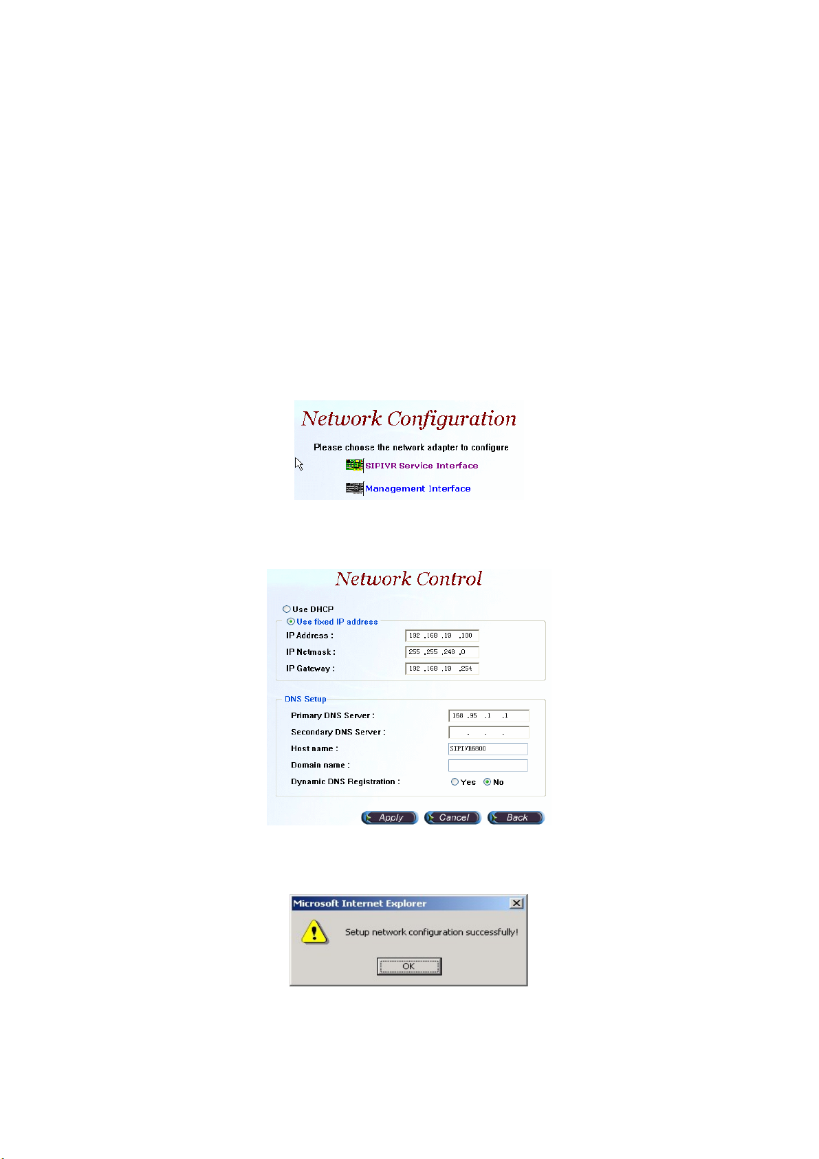
2.3.3 Network
Step 1: After successfully logon to the system, we need to change the network
configuration. Click Control>Network, the screen will display as figure
2.3-5.Choose the interface to be modified.
Figure 2.3-5
Step 2: Enter the deserved IP address, Submask and default gateway. Apply
the change by clicking apply button as figure 2.3-6.
Figure 2.3-6
Step 3: When screen shows “Setup network configuration successfully!”
It means the IP Network setting is successfully changed as figure 2.3-7.
Figure 2.3-7
“Network Control” takes around 5-second to apply the new network
configuration. Please logon again with new IP address after 5 seconds.
36
Page 38
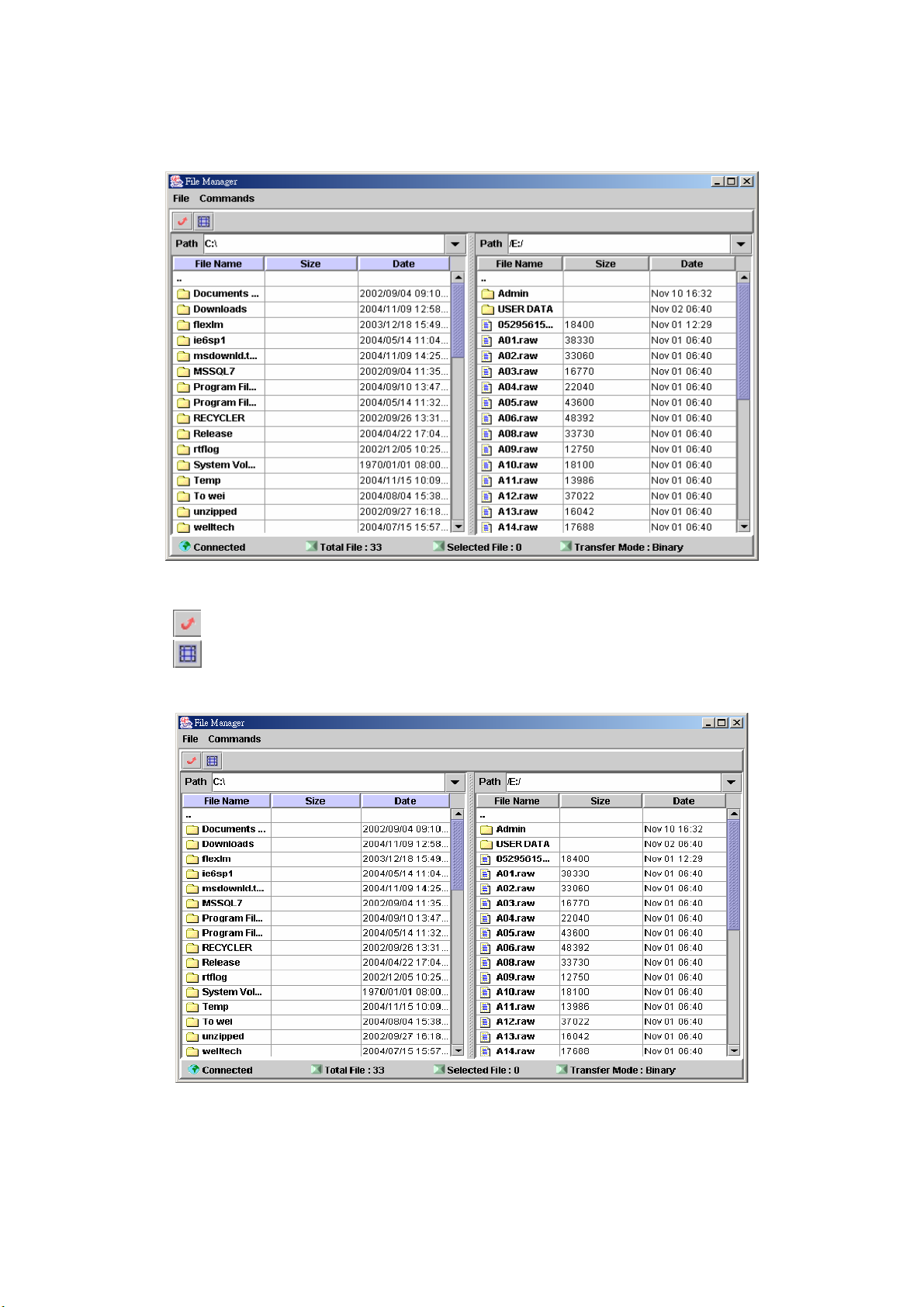
2.3.4 File Manager
Start path: Click Control>File Manager
Figure 2.3-8
ToolBar Description:
● :Refresh File Manager
● :Toggle on/off the gridlines
Step 1: Click Control>File Manager, the screen will display as figure 2.3-9.
Figure 2.3-9
Step 2: To download file from IVR server, click Commands>Download. Or
right click the download file and select Download as figure 2.3-10.
37
Page 39
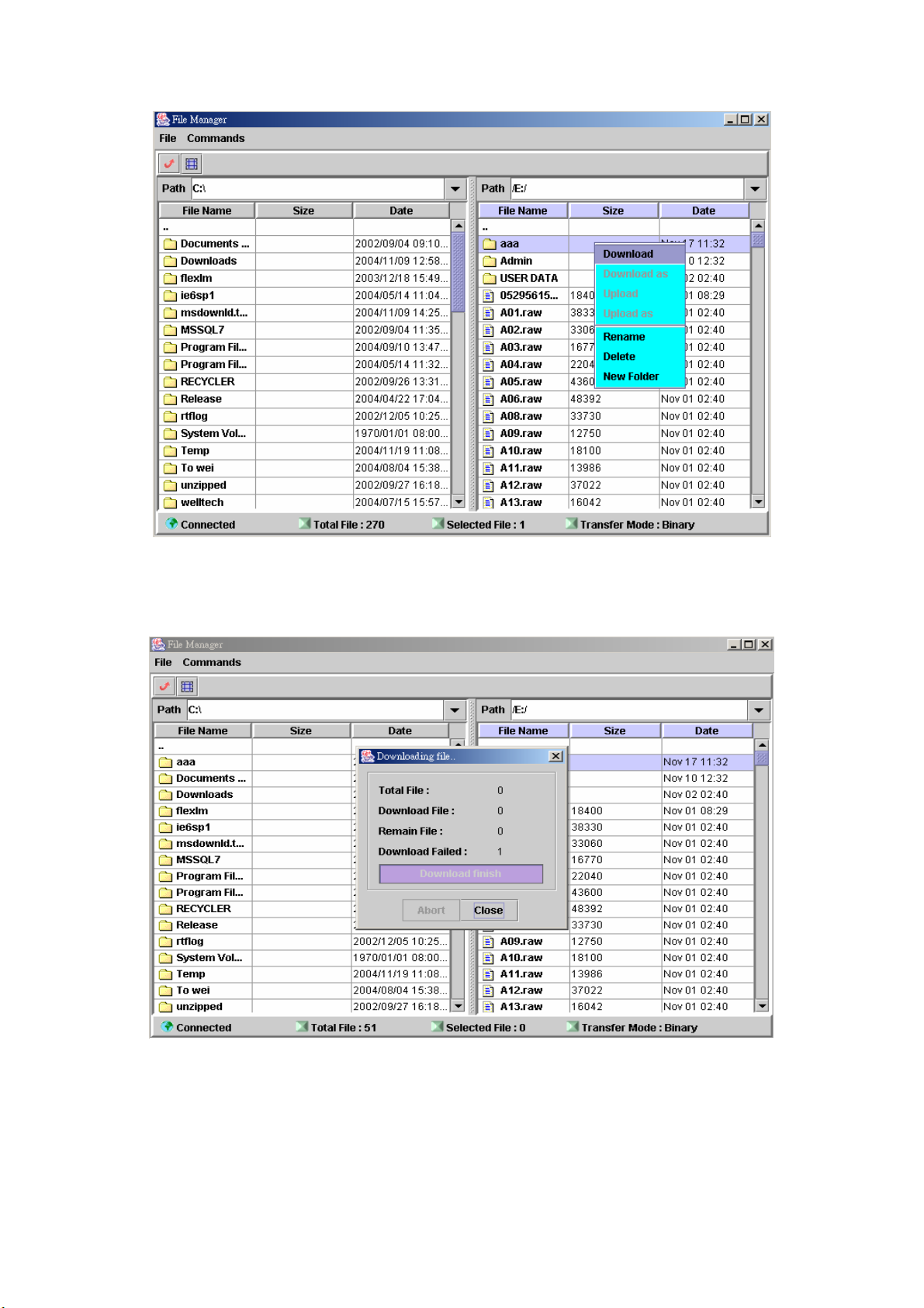
Figure 2.3-10
Step 3: When download is started, a progress box will be displayed to indicate
the download result. Download As can be used for saving into a new
file.
Figure 2.3-11
Step 4: To upload the file, click Commands>Upload. Or right click the upload
file and select Upload as figure 2.3-12.
38
Page 40
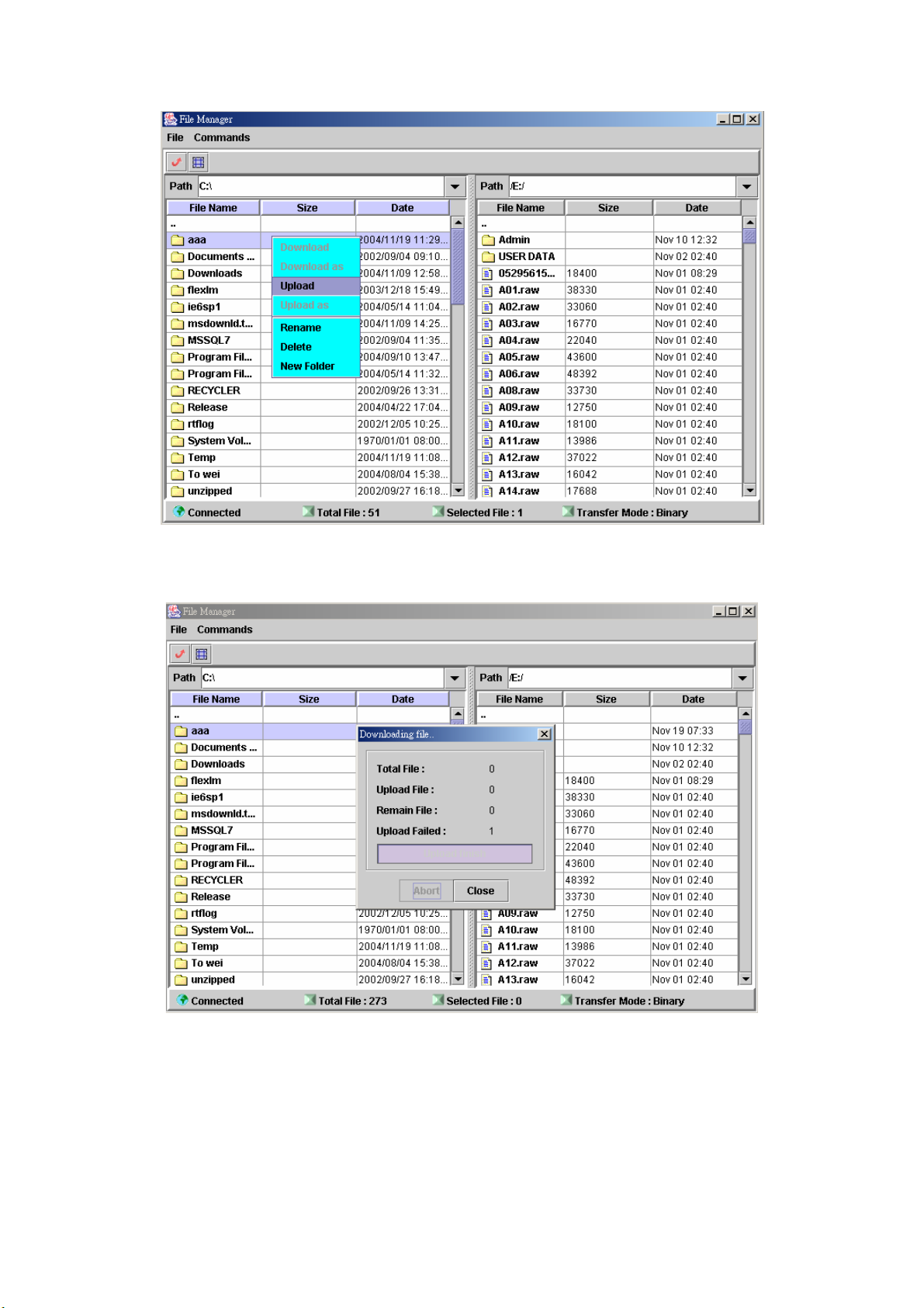
Figure 2.3-12
Step 5: When upload is started, a progress box will be displayed to indicate the
upload result. Upload As can be used for saving into a new file.
Figure 2.3-13
Step 6: To delete the file, click Commands>Delete as figure 2.3-14 (Or right
click the file and select Delete).
39
Page 41
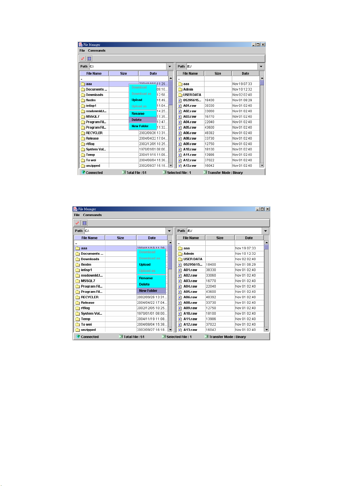
Figure 2.3-14
Step 7: To add a new folder, click Commands>New Folder as figure 2.3-15
(Or right click the file and select New Folder).
Figure 2.3-15
2.3.5 Prompt Manager
Start Path: Control>Prompt Manager
In order to use the prompt manager in IE, please add the SIPIVR 6800 IP into
your trust host list of IE.
Step 1: Click Control>Prompt Manager, the runner manager screen will
display as figure 2.3-16.
40
Page 42

Figure 2.3-16
New, Record:
Step 2: Make sure you have installed microphone or other device when you
want to record, Click New and Record buttons to record as figure
2.3-17.
Figure 2.3-17
Stop, Pause, Play:
Step 3: Click Stop or Pause button to stop record, and click Play button to
listen the voice prompt as figure 2.3-18.
Figure 2.3-18
Save:
Step 4: Click Save button to saving the voice.
Save the file to a new name can be use Save As (
41
).
Page 43

Save Remote File:
Step 5: Click Save Remote File to saving the voice file to remote server.
Save the file to a new name can be use Save Remote File As ( ).
Open Remote File:
Step 6: Click Open Remote File button to open voice file and the screen
shows Choose file as figure 2.3-19.
Figure 2.3-19
Open:
Step 7: Click Open button to open local host voice file and screen shows
Choose File as figure 2.3-20.
Figure 2.3-20
Close:
Step 8: Click Close button to close the voice file as figure 2.3-21.
Figure 2.3-21
42
Page 44

Copy:
Step 9: Select the desired voice range and click Copy button as figure 2.3-22.
Figure 2.3-22
Paste:
Step 10: Click Paste button to paste the voice range as figure 2.3-23.
Figure 2.3-23
Cut:
Step 11: Select the desired voice range and click Cut button as figure 2.3-24.
Figure 2.3-24
43
Page 45

Undo:
Step 12: Click Undo button to return modification, you can see the
configuration hasn’t be changed as figure 2.3-25.
Figure 2.3-25
Redo: Refer Section “Undo”
Zoom Zoom In Zoom Out:
Step 13: Select the desired voice range click Zoom button as figure 2.3-26.
Figure 2.3-26
Step 14: The screen shows the zoom out voice file range as figure 2.3-27.
Figure 2.3-27
44
Page 46

Delete Remote file:
Step 15: Click Delete Remote file button to delete remote voice file as figure
2.3-28.
Figure 2.3-28
2.3.6 Account Manager
Step 1: You can manage your user account by click Control>Account
Manager. Click New button to add a new user account as figure 2.3-29.
Figure 2.3-29
Step 2: Enter the new user ID, Password. Apply the change as figure 2.3-30.
Figure 2.3-30
Field Description:
• User ID: Login User ID
• Password: Login Password
• Confirm Password: Confirm new password again
Step 3: When screen shows “Create user account successfully!” It means
user account setting is successfully created as figure 2.3-31.
45
Page 47

Figure 2.3-31
2.3.7 Upgrade
Step 1: Click “Control>Upgrade” to upgrade the software as figure 2.3-32.
Figure 2.3-32
2.3.8 Relogin
Step 1: Click Control>Relogin to relogon by another user account as figure
2.3-33.
Figure 2.3-33
Step 2: Enter new User ID and Password to re-logon the IVR as figure 2.3-34.
Figure 2.3-34
Step 3: The screen shows the Home Page of Win IVR as figure 2.3-35.
Figure 2.3-35
46
Page 48
Chapter 3 Call flow Menus and Tools
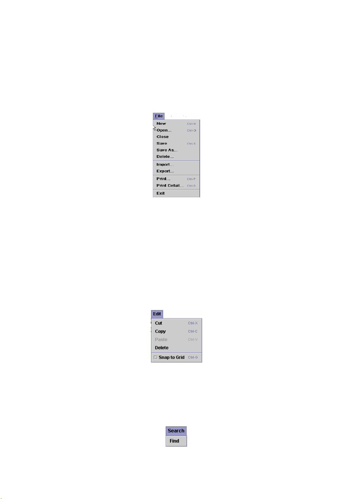
3.1
File Menu
The file menu is similar to file menus in virtually all Windows based
applications. Click on the Call Flow Manager and select an item, then you can
edit the call flow by clicking the Edit button. If you select "File", this pull down
menu is displayed as figure 3-1.
Figure 3-1
New: Created a new call flow
Open: Open an existing flow
Close: Close the call flow
Save: Save the call flow
Save as: To save the call flow to a new name
Delete: Delete the call flow
Import: Import the selected file into a new call flow
Export: Export the call flow into a flat file
Print: Print
Print Detail: Print the call flow detail
Exit: Quit the system
3.2 Edit Menu
Figure 3-2
The "View" pull down menu includes these functions:
Cut, Copy, Paste: Let you cut and copy icon to the clipboard which can
then be copied or pasted into the call flow.
Delete: Remove the selected icons.
Snap to Grid: Automatically align the icon with grid line or not.
3.3 Search Menu
Figure 3-3
47
Page 49
The "Search" pull down menu includes these functions:
Find: Search component by component ID or component type.
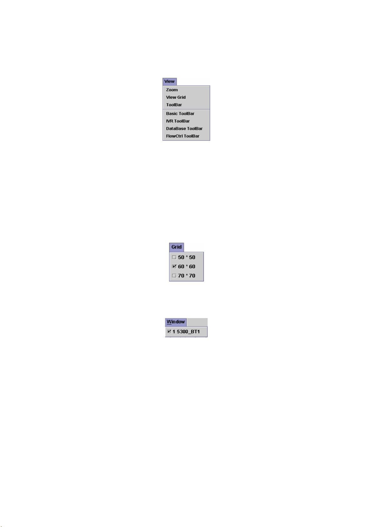
3.4 View Menu
Figure 3-4
The "View" pull down menu includes these functions:
Zoom: Zoom in and zoom out to make your call flow diagram larger or
smaller.
View Grid: Toggle on/off the gridlines.
ToolBar: Toggle on/off the icon palettes for Menu Toolbar.
Basic ToolBar: Toggle on/off the icon palettes for Basic Toolbar.
IVR ToolBar: Toggle on/off the icon palettes for IVR Toolbar.
Database ToolBar: Toggle on/off the icon palettes for Database Toolbar.
FlowCtrl ToolBar: Toggle on/off the icon palettes for FlowCtrl Toolbar.
3.5 Grid Menu
Set the grid size.
3.6 Window Menu
Show the opened call flow.
Figure 3-5
Figure 3-6
48
Page 50
Chapter 4 IVR Function
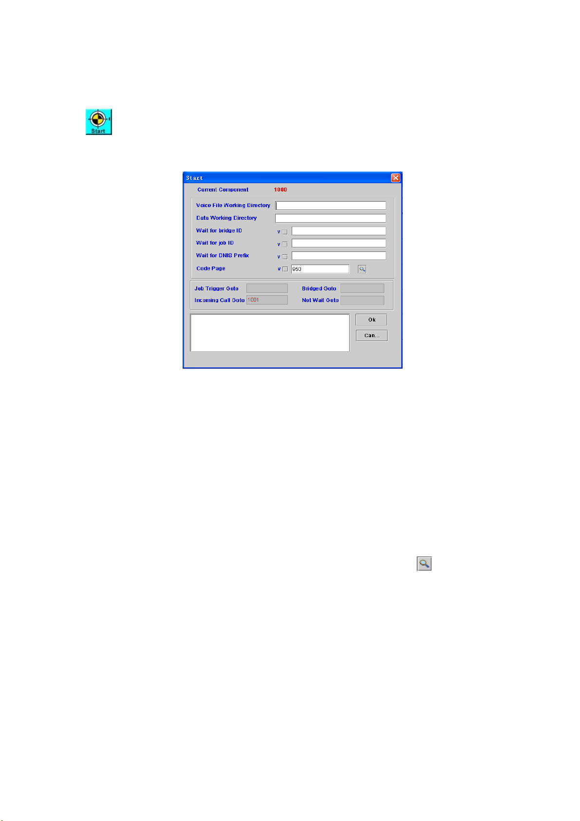
Start: Call flow start
[Description]
Right-click the Start component, the screen appears as figure 4-1.
Figure 4-1
Voice File Working Directory: The directory to store those voice file or
default working directory.
Data Working Directory: The directory to store those voice file or working
directory.
Wait for bridge ID: To accept a bridge ID request from another channel.
Only the assigned bridged ID will trigger to the next component (Bridge
Goto)
Wait for job ID: To accept a JOB ID request from external or internal Job
server. Only the assigned JOB ID will trigger to the next component (Job
Trigger Goto)
Wait for DNIS Prefix: To accept the called number prefix. Only the called
number (DNIS) prefix is matched the assigned prefix will trigger the
“Incoming Call Goto” component
Code Page: The HTML language code page, you can click
other code page number
Job Trigger Goto: The next component to be executed when received a
Job request from Job Server. It only working when “Wait for job ID” is
checked and the same JOB ID is received from Job server.
Bridged Goto: The next component to be executed when the bridge is
established.
Incoming Call Goto: When the called number is matched the “Wait for the
DNIS prefix” value, SIPIVR 6800 will execute the “Incoming Goto”
component ID.
Not Wait Goto: The “Not Wait Goto” will be only triggered when there is no
any “Job trigger Goto”, “Bridged Goto” and “Incoming Call Goto” is defined.
It can be used to do some polling job.
Remark: Description or remark for this component
to select
49
Page 51
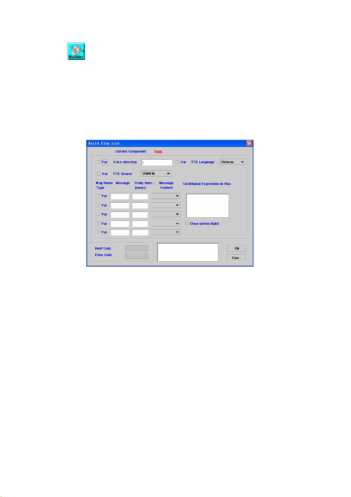
4.1 Build Play List
[Introduction]
Build Play List component is used to play more than 10 voice messages
at a time. You can have more than one Play List Builder component to extend
the play list. The system can only concurrently keep a play list for a channel.
You can start play by using Play, Play A&D and Play Cut component. Please
see the section 4.3, 4.4, 4.5.
[Description]
Right-click the Build Play List component, the screen appears as figure
4-1.
Figure 4-1
Voice directory: Sets a directory for voice files (Check "Var" when the
working voice directory is stored at a variable), for http play back, please
refer to Play Announcement component.
TTS Language: The selection of speech language
TTS Source: The source of TTS language
- Build-in: Use the build-in text for speech language
- Customize #1-4: Use the customer defined language.
Msg Name Type: Check “Var” box to indicate that the message string is a
variable name
Message: Messages or variable names to be played
Delay Interval (msec): Silence delay before next message
Message Content: The played format of the message
Voice File: pre-recorded G.711 mu-law raw file or wav file
Voice List: It is used for customized TTS by using hook. Please refer to
“How to implement customized TTS?”
Date ( format: yyyy/mm/dd or yyyy-mm-dd )
Time ( format: hh:mm:ss or hh:mm )
Currency
Numeric
Digit /Alphabet( English, up to 23 characters )
Text( (Chi)
Conditional Expression to Run: If the result of expression is "True", add
50
Page 52
messages of this component to play list. Or skip it.
Clear before Build: Check to empty the play list before execute
Next Goto: Next component to be executed if the operation is successful
Error Goto: Next component to be executed if an error is occurred
Remark: Description or remark for this component
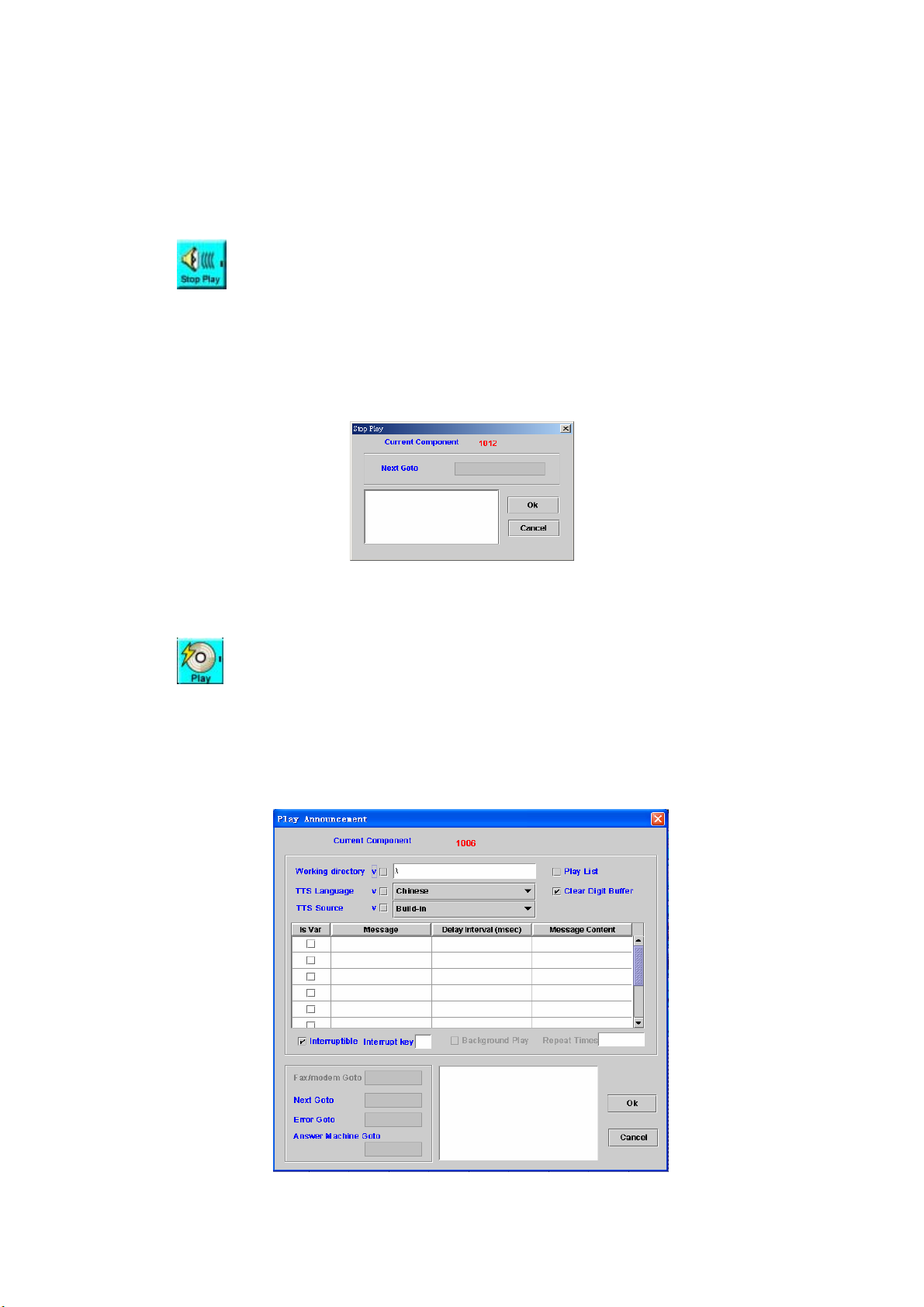
4.2 Stop Play
[Introduction]
Stop Play component is used to stop background play of Play
Announcement component. (Please refer to the section 4.3)
[Description]
Right-click the Stop Play component, the screen appears as figure 4-2.
Figure 4-2
Next Goto: Next component to be executed
Remark: Description or remark for this component
4.3 Play Announcement
[Introduction]
The Play Announcement component can play up to 10 voice messages.
[Description]
Right-click the Play Announcement component, the screen appears as
figure 4-3.
Figure 4-3
51
Page 53

Working directory: Set a directory for voice files (Check "Var" when the
working voice directory is stored at a variable). If you are using http play
back. Please set the working directory to http://ip/dir. An example is
http://192.168.12.1/voicefile/. The message only input the file name in
http server.
Play List: Check this box to play the current Play List instead of
individual voice message setup in this component (Please refer to
section 4.1)
TTS Language: The selection of speech language
TTS Source: The source of TTS language
- Build-in: Use the build-in text for speech language
- Customize #1-4: Use the customer defined language.
Clear Digit Buffer: To clear the digit buffer before start to play
Is Var: Check “Is Var” box to indicate that the message string is a
variable name
Message: Messages or variable names to be played
Delay Interval (msec): Silence delay before next message
Message Content: The played format of the message
Voice File: pre-recorded G.711 mu-law raw file or wav file
Date ( format: yyyy/mm/dd or yyyy-mm-dd )
Time ( format: hh:mm:ss or hh:mm )
Currency
Numeric
Digit/Alphabet ( English, up to 23 characters )
Text (Chi)(Traditional Chinese Text,up to 23 characters )
Interruptible: Stop play or not when user press the specified DTMF
Interrupt Key: Set Interrupt Key (0-9,*, #). Blank is used for any key
Background Play: Checks it to enable background play when your call
flow wants to do other task simultaneously (e.g. DB query). The channel
will go to next component immediately. The play will run on background
until reached the stop play component or play end condition.
Repeat Times: Set Background Play repeat times
Fax/modem Goto: Next component to be executed if the target is
a fax or modem.
Next Goto: Next component to be executed if the operation is
successful
Error Goto: Next component to be executed if an error is occurred
Answer Machine Goto: Next component to be executed if the target is
an answer machine
Remark: Description or remark for this component
4.4 Play Announcement & Collect Digits
[Introduction]
The Play Announcement & Collect Digits component can play up to 10
voice messages and collect input digits.
[Description]
Right-click the Play Announcement & Collect Digits component, the
screen appears as figure 4-4.
52
Page 54
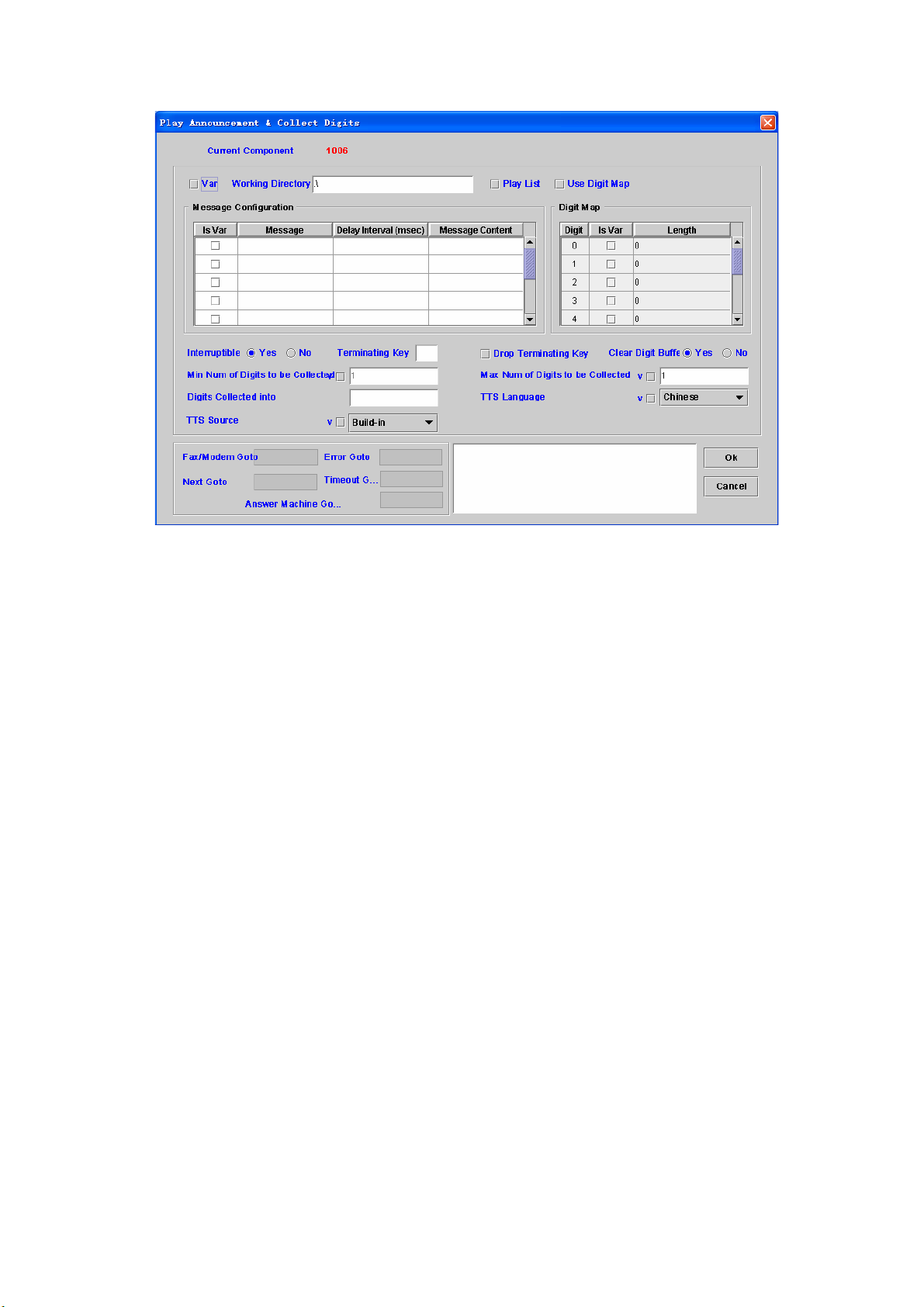
Figure 4-4
Working directory: Set a directory for voice files. For http play back,
please refer to Play Announcement component.
Play List: Check this box to play the current Play List instead of
individual voice message setup in this component (Please refer to
section 4.1)
Use Digit Map: Whether to enable the Digit Map
Is Var: Check “Is Var” box to indicate that the message string is a
variable name
Message: Messages or variable names to be played
Delay Interval (msec): Silence delay before next message
Message Content: The played format of the message
Voice File: pre-recorded G.711 mulaw raw file or wav file
Data ( format: yyyy/mm/dd or yyyy-mm-dd )
Time ( format: hh:mm:ss or hh:mm )
Currency
Numeric
Digit/Alphabet ( English, up to 23 characters )
Text(Chi)( Traditional Chinese text, up to 23 characters )
Digit Map
Digit: Leading Digit
Is Var: Check “Is Var” box to indicate that the message string is a
variable name
Length: constant length value or length variable
Interruptible: Stop play or not when user press the specified DTMF
Terminating Key: Set Terminating Key (0-9,*, #). Blank is used for any
key
Drop Terminating Key: Check to drop the terminating key
Clear Digit Buffer: To clear the digit buffer before start to play
Use Digit Map: Check to collect user input based on DTMF prefix (dial
pad).
53
Page 55
Min Num of Digits to be Collected: Minimum number of collected digit
Max Num of Digits to be Collected: Maximum number of collected digit
Digits collected into: Store the collected digits into a variable
TTS Language: The selection of speech language
TTS Source: The source of TTS language
- Build-in: Use the build-in text for speech language
- Customize #1-4: Use the customer defined language.
Fax/modem Goto: Next component to be executed if the target is
a fax or modem.
Error Goto: Next component to be executed if an error is occurred
Next Goto: Next component to be executed if the operation is successful
Timeout Goto: Next component to be executed if the server waits input
digits timeout. (The first and inter digit timeout can be changed by
"Collect Digit Option" component. Please refer to section 4.15).
Answer Machine Goto: Next component to be executed if the target is
an answer machine
Remark: Description or remark for this component
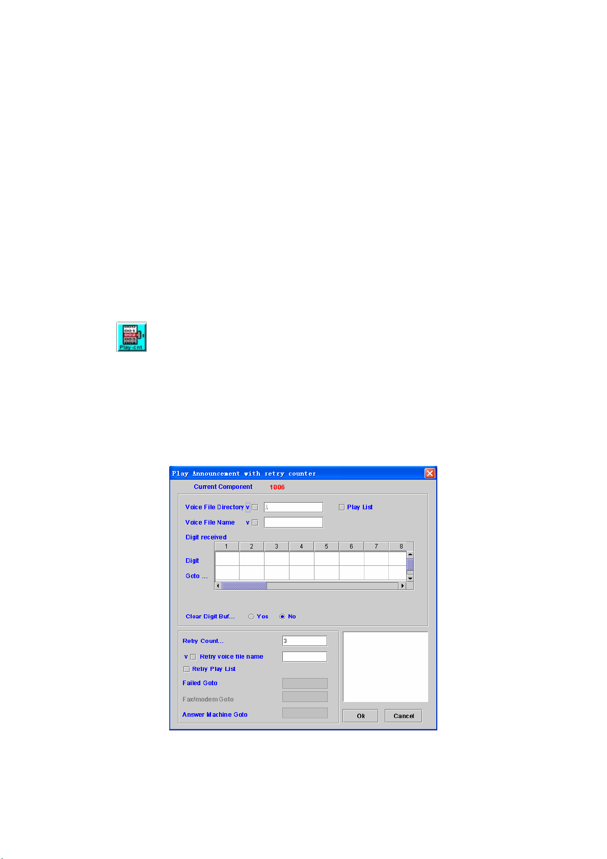
4.5 Play Announcement with Retry Counter
[Introduction]
The Play Announcement with Retry Counter component can play voice
file, collect user digits and retry until the input digit met defined criteria or
reached max retry.
[Description]
Right-click the Play Announcement with Retry Counter component, the
screen appears as figure 4-5.
Figure 4-5
Voice File Directory: Set a directory for voice files (Check "V" when the
voice file directory is stored at a variable)
54
Page 56
Voice File Name: Voice file name to be played (Check "V" when voice file
name is stored at a variable)
Play List: Check this box to play the current Play List instead of
individual voice message setup in this component (Please refer to
section 4.1)
Digit Received
Digit: matched collect digits
Goto CID: Next component to be executed if the input digits are
matched
Clear Digit Buffer: To clear the digit buffer before start to play.
Retry Counter: Max retry count when user input doesn't match any
defined digits. Sets to zero for infinite retry.
Retry Voice File Name: Voice file will be played when user input doesn't
match any defined digits. After this voice announcement is played, will
re-execute this component until reach retry counter.
Retry Play List: Check this box to play the current Play List instead of
individual retry file setup in this component (Please refer to section 4.1)
Failed Goto: Next component to be executed if user input cannot met
defined digits and reached max retry count.
Fax/modem Goto: Next component to be executed if the target is
a fax or modem.
Answer Machine Goto: Next component to be executed if the target is
an answer machine
Remark: Description or remark for this component.
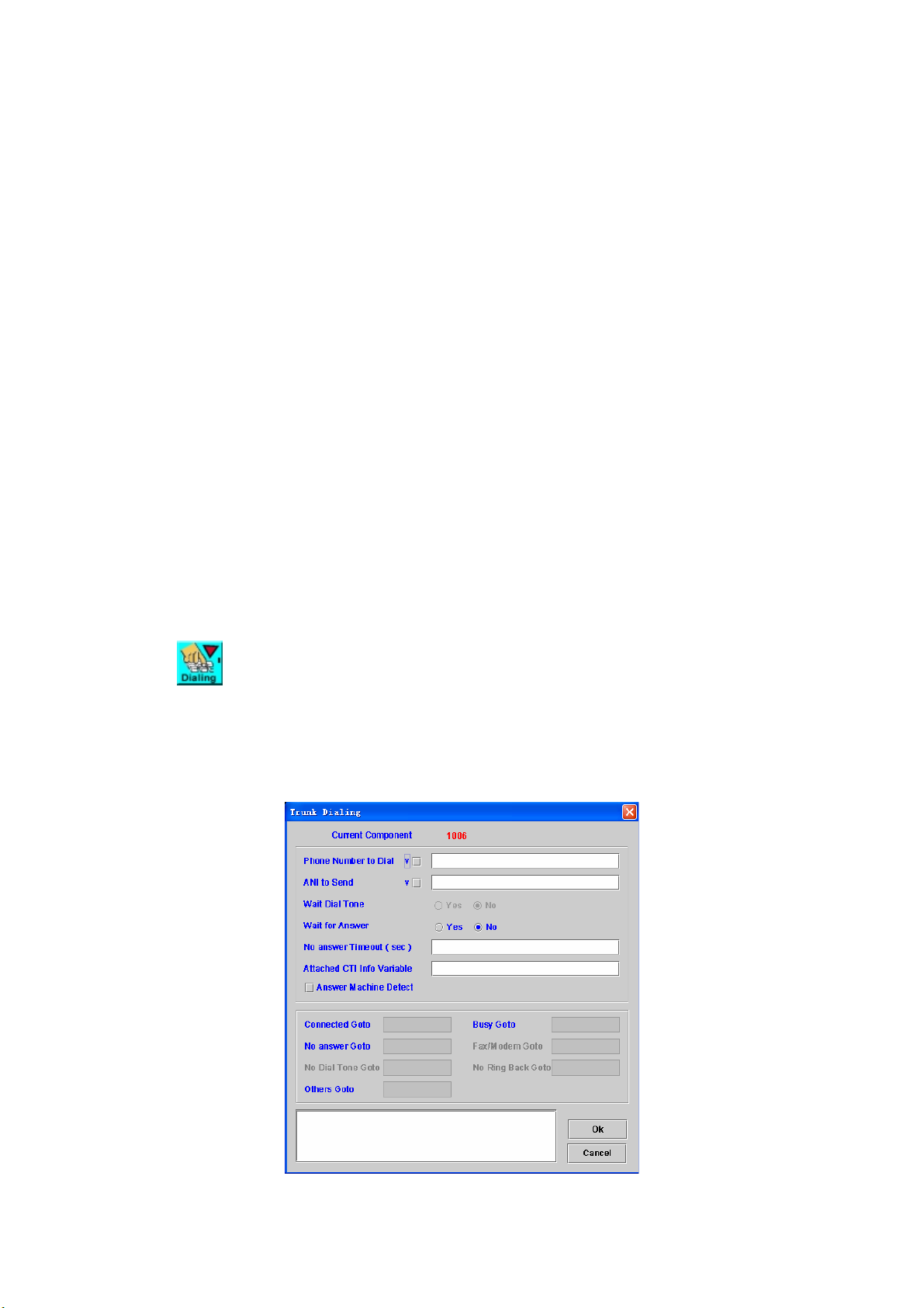
4.6 Trunk Dialing
[Introduction]
Trunk Dialing component is used to make an outbound call.
[Description]
Right-click the Trunk Dialing component, the screen appears as figure 4-6.
Figure 4-6
55
Page 57
Phone Number to Dial: Phone number to be dialed
ANI to Send: Calling party number to be sent
Wait Dial Tone: revered
Wait for Answer: Decide whether stay at this component until the called
party answer it. If choosing no waiting, the flow will go to next component
immediately that indicates by Connected Goto.
No answer Timeout (sec): The maximum time of waiting for answer
Attached CTI Info Variable: The stored variable of CTI message will be
sent to another channel.
Answer Machine Detect: Enable the answer machine detect or not
Connected Goto: Next component to be executed if it’s connected
Busy Goto: Next component to be executed if the called party is busy
No Answer Goto: Next component to be executed if the called party is no
answer
Fax/Modem Goto: Next component to be executed if the target is a fax or
modem
No Dial Tone Goto: Next component to be executed if no dial tone is
returned.
No Ring Back Goto: Next component to be executed if no ring back tone
(no SIP 18x) is received.
Others Goto: Next component to be executed if the result is others
Remark: Description or remark for this component
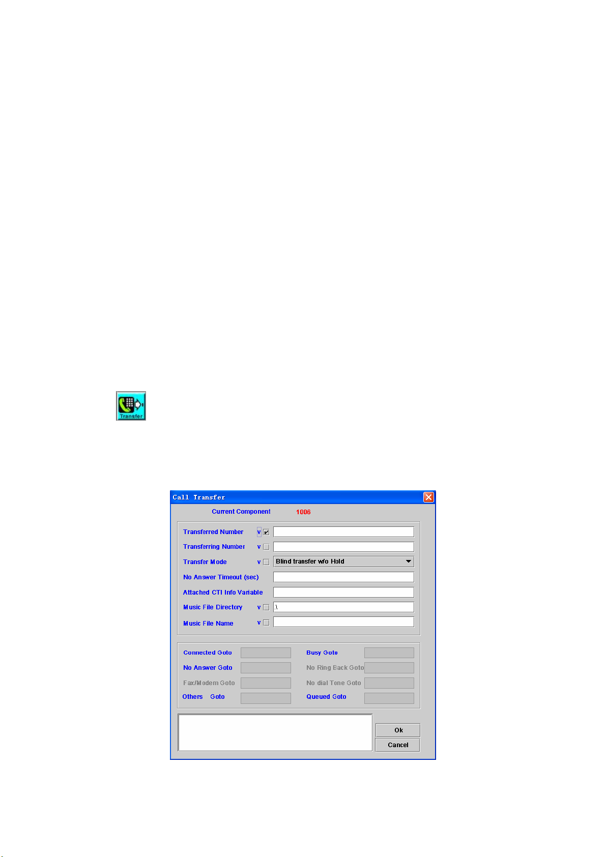
4.7 Call Transfer
[Introduction]
Call Transfer component is used to transfer a call to another number.
[Description]
Right-click the Call Transfer component, the screen appears as figure 4-7.
Figure 4-7
56
Page 58

Transferred Number: The phone number used to be transferred.
Transferring Number: SIP refer-by phone number. It might be used to
show different calling number for transferred party.
Transfer Mode: The mode of transfer
- Blind Transfer w/o Hold: This mode can be used only if remote party
can support transfer without hold. In this case, the SIPIVR can
continue to play the announcement during the transfer period.
- Blind Transfer: If checked, the SIPIVR 6800 will send REFER to
transferee party without making call to transferred party (Unattended
call transfer).
- Attend transfer: The SIPIVR 6800 will call the transferred party first.
Then SIPIVR can play announcement to the transferred party. The
calling party will still in hold state until SIPIVR get into the on-hook
component.
No Answer Timeout: The maximum time of waiting for call transfer result
Attached CTI Info Variable: The stored variable of CTI message that will
be sent to another channel. (only available for 8680 model)
Music File Directory: The directory of music hold file
Music File Directory: The name of music hold file
Connected Goto: Next component to be executed if it’s connected
Busy Goto: Next component to be executed if the called party is busy
No Answer Goto: Next component to be executed if the called party is no
answer
No Ring Back Goto: Next component to be executed if no ring back tone
(no SIP 18x) is received.
Fax/modem Goto: Next component to be executed if the target is
a fax or modem.
No Dial Tone Goto: Next component to be executed if no dial tone is
returned.
Others Goto: Next component to be executed if the result is others
Queued Goto: Next component to be executed if the target is queued. It
can be only used for 8680 model and required to connect to ICCS 8650
for call center solution to play the queuing order and waiting time. Please
contact to Welltech before to use it.
Remark: Description or remark for this component
4.8 Bridge
[Introduction]
The Bridge component provides a function for connecting two physical
channels or self bridge.
[Description]
Right-click the Bridge component, the screen appears as figure 4-8.
57
Page 59

Figure 4-8
Bridge Group ID: It’s used to identify the bridge group. Only same group
ID defined in Start component will accept the bridge request.
Voice Directory: Set a directory to voice files
Play File Name: The voice file to be play during the bridge.
Max Bridge Wait Time (sec): The maximum time to wait for bridge result
Max Bridge Time (sec): The maximum bridge time after bridge is
established (connect state). It can be used to disconnect the bridge for
prepaid service.
ANI: Calling party number
two channels bridge
ANI will be carried to bridged channel into "__ANI" variable.
Self-Bridge
Calling party number to be used for 2nd call
DNIS: Called party number
two channels bridge
DNIS will be carried to bridged channel into "__DNIS" variable.
Self-Bridge
Called party number to be used for 2nd call
Bridged time to Variable: Output variable for total bridge time when using
self-bridge.
Time to Expired Notice(30-120): The expired notify time before max
bridge time
Expire Notice File: The announcement will be played as a expired notice
Notice Target: The target which will hear the announcement
Self Bridge: Used for one Channel Bridge. RTP is sent and received by
58
Page 60

first party and third party. Only SIP signal is involved by SIPIVR 6800.
Quit On Bridged: Quit the component after the two calls are connected.
Bridge Forever: Unlimited max bridge time
Attached CTI Info Variable: The stored variable of CTI message that will
be sent to another channel.
Bridge Var: Pass Variables to the bridged channel
Fail Goto: Next component to be executed if an error is occurred
User Stop Goto: Next component to be executed if this call be hanged up
by third party after two channels is bridged
Timeout Goto: Next component to be executed if this channel waits "Max
Bridge Wait Time" time out
Done Goto: Next component to be executed when "Max Bridge Time" is
reached.
Quit On Bridged Goto: Next component to be executed when quit the
Bridge.
Remark: Description or remark for this component
4.9 Bridge Result
[Introduction]
The Bridge Result component provides a function that returns the
execution result for bridge request (Please refer to the section 4.8).
[Description]
Right-click the Bridge Result component, the screen appears as figure 4-9.
Figure 4-9
Bridge Result: Set the attribute of the result
Done: bridge success and start to talk
Fail: failed to make second call
Result Variable: Variables returned to the bridging channel
Quit immediately: Quit this component to “Done Goto” after execute
Bridge Result. It is normally unchecked for the bridged call (second
outgoing call) because it needs to be run until hang-up.
Fail Goto: Next component to be executed if an error is occurred
User Stop Goto: Next component to be executed if this call be hanged up
by first party after two channels bridged
59
Page 61

Done Goto: Next component to be executed if "Max Bridge Time" that
defined by Bridge component is reached.
Remark: Description or remark for this component
4.10 On Hook
[Introduction]
On Hook component is used to hang up the call. It’s the last component in
the call flow normally.
[Description]
Right-click the On Hook component, the screen appears as Figure 4-10.
Figure 4-10
ANI: The calling party number**
DNIS: The called party number**
User ID: The user account**
Password: The user password**
Credit Time(sec): The max talk time will be send to 6500**
CTI Data: The stored variable of CTI message that will be sent to
another channel (only available for 8680 model). It can be used for call
center agent to release a call to SIPIVR for doing some checking or
validation and send back CTI information for result. The call center agent
need wait until IVR send the result back.
Remark: Description or remark for this component
** These parameters are optional. It is used to carry RADIUS account
information via SIP header for 6500 in order to do the prepaid service.
Those corresponding SIP headers are: __ANI, __DNIS, __USERID,
__PASSWORD, __CreditTime
4.11 Answer
[Introduction]
Answer incoming call.
[Description]
Right-click the Answer component, the screen appears as figure 4-11.
60
Page 62

Figure 4-11
Next Goto: Next component to be executed
Remark: Description or remark for this component
4.12 Send DTMF
[Introduction]
Send DTMF to remote party
[Description]
Right-click Send DTMF component, the screen appears as figure 4-12.
Figure 4-12
Send DTMF: DTMF to be sent
Success Goto: Next component to be executed if the operation is
successful
Error Goto: Next component to be executed if an error is occurred
Remark: Description or remark for this component
4.13 Record
[Introduction]
Record component is used to record voice into a file.
[Description]
Right-click the Record component, the screen appears as figure 4-13.
61
Page 63

Figure 4-13
Working Directory: Set a directory for voice files. For http recording, it
supports both POST (tested only for hfs from http://www.rejetto.com/hfs/)
and PUT (tested for IIS). The format for POST method is:
m=POST,u=usedid,p=password,http://fileserver/voicedir. The format for
PUT method is: m=PUT,u=userid,p=password,http://fileserver/voicedir. u
and p parameter can be omitted if server doesn’t need authentication.
File Name: The voice file name to be recorded
Variable Counter: Append this counter value to the tail of File Name and
increase it by Count Increment
Counter increment: The increase number for Variable Counter
Interruptible: Stop record when user press the specified DTMF or not
Interrupt Key: Set Interrupt Key (0-9,*, #). Blank is used for any key
Max Sec to Record (sec): Maximum time allowed for recording
Max Silence to Record (sec): Stop recording when maximum silence is
reached
Play Beep to Start: Play beep before recording the voice
Next Goto: Next component to be executed
Error Goto: Next component to be executed if an error is occurred
Remark: Description or remark for this component.
4.14 Volume Speed Set
[Introduction]
To adjust playing voice volume and speed
[Description]
Right-click the Volume Speed Set component, the screen appears as
Figure 4-14.
62
Page 64
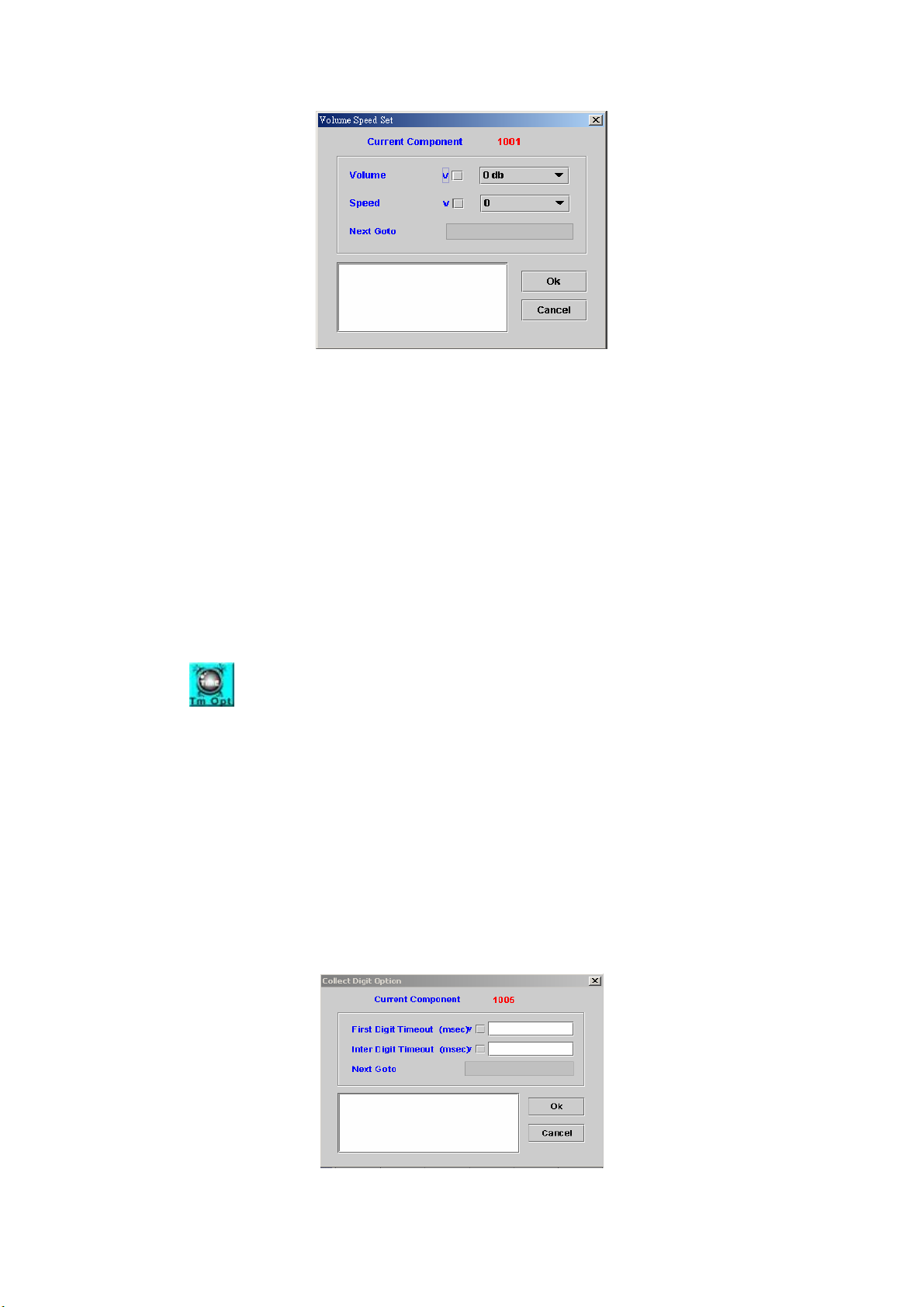
Figure 4-14
Volume: Adjust voice volume (-31 db to 31 db)
Speed: Adjust voice speed (4 to –4)
0: Normal
1: 1.25 faster
2: 1.5 faster
3: 1.75 faster
4: 2 faster
-1: 0.8 slower
-2: 0.67 slower
-3: 0.57 slower
-4: 0.3 slower
Next Goto: Next component to be executed
Remark: Description or remark for this component
4.15 Collect Digit Option
[Introduction]
Adjust the collecting digit timeout parameter. The system will keep the
adjustment until next Collect Digit Option component is executed. The first
digit default timeout is 10 seconds, and interval digit default timeout is 5
seconds.
This component affects the collect digit time of Play Announcement &
Collect Digits and Play Announcement with Retry Counter components.
Please refer sections 4.4 and 4.5, respectively.
[Description]
Right-click the Collect Digit Option component, the Collect Digit Option
screen appears as Figure 4-15.
Figure 4-15
63
Page 65
First Digit Timeout (msec): The maximum time for waiting the first digit
Inter Digit Timeout (msec): The maximum time for waiting between two
digits
Next Goto: Next component to be executed if the operation is successful
Remark: Description or remark for this component
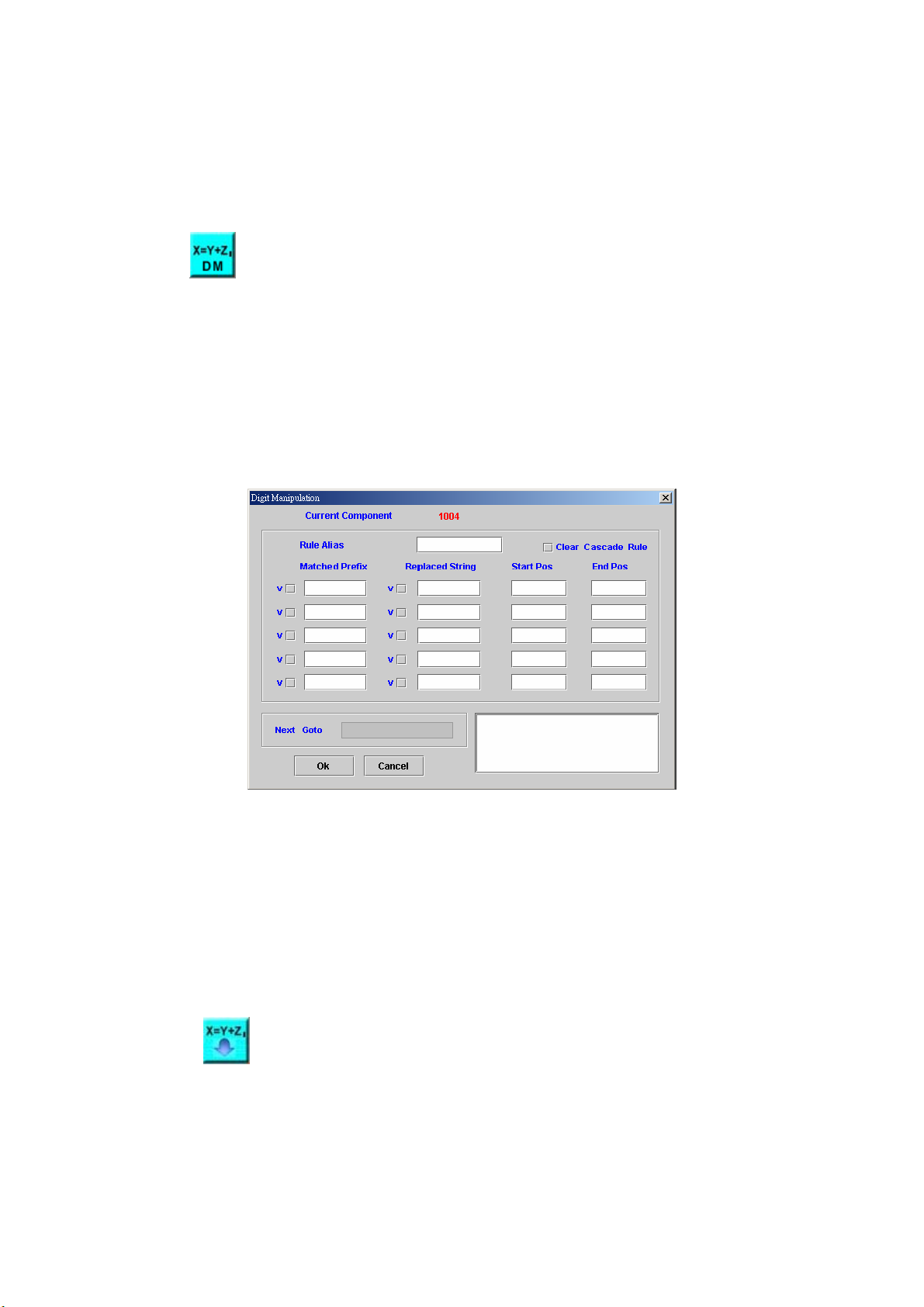
4.16 Digit Manipulation Builder
[Introduction]
This component is used to make a digit manipulation list. We could use
this list to manipulate an input string that assigned by Execute Digit
Manipulation component in section 4.17. If manipulated string had same prefix
as Matched Prefix, the system will delete characters from Start Pos to End
Pos, and insert Replaced String to the manipulated string at Start Pos.
[Description]
Right-click the Digit Manipulation Builder component, the screen
appears as figure 4-16.
Figure 4-16
Rule Alias: Used to identify a digit manipulation list
Clear Cascade Rule: Check to clear the digit manipulation list with Rule
Alias name
Matched Prefix: Set a string to be matched
Replaced String: Set a string to be replaced
Start Pos: Start position to be deleted and insert
End Pos: Stop position to be deleted
Next Goto: Next component to be executed
Remark: Description or remark for this component
4.17 Execute Digit Manipulation
[Introduction]
The Execute Digit Manipulation component is used to manipulate a
string. The rule of manipulation is made by the Digit Manipulation Builder
component that discussed in the section 4.16.
[Description]
64
Page 66
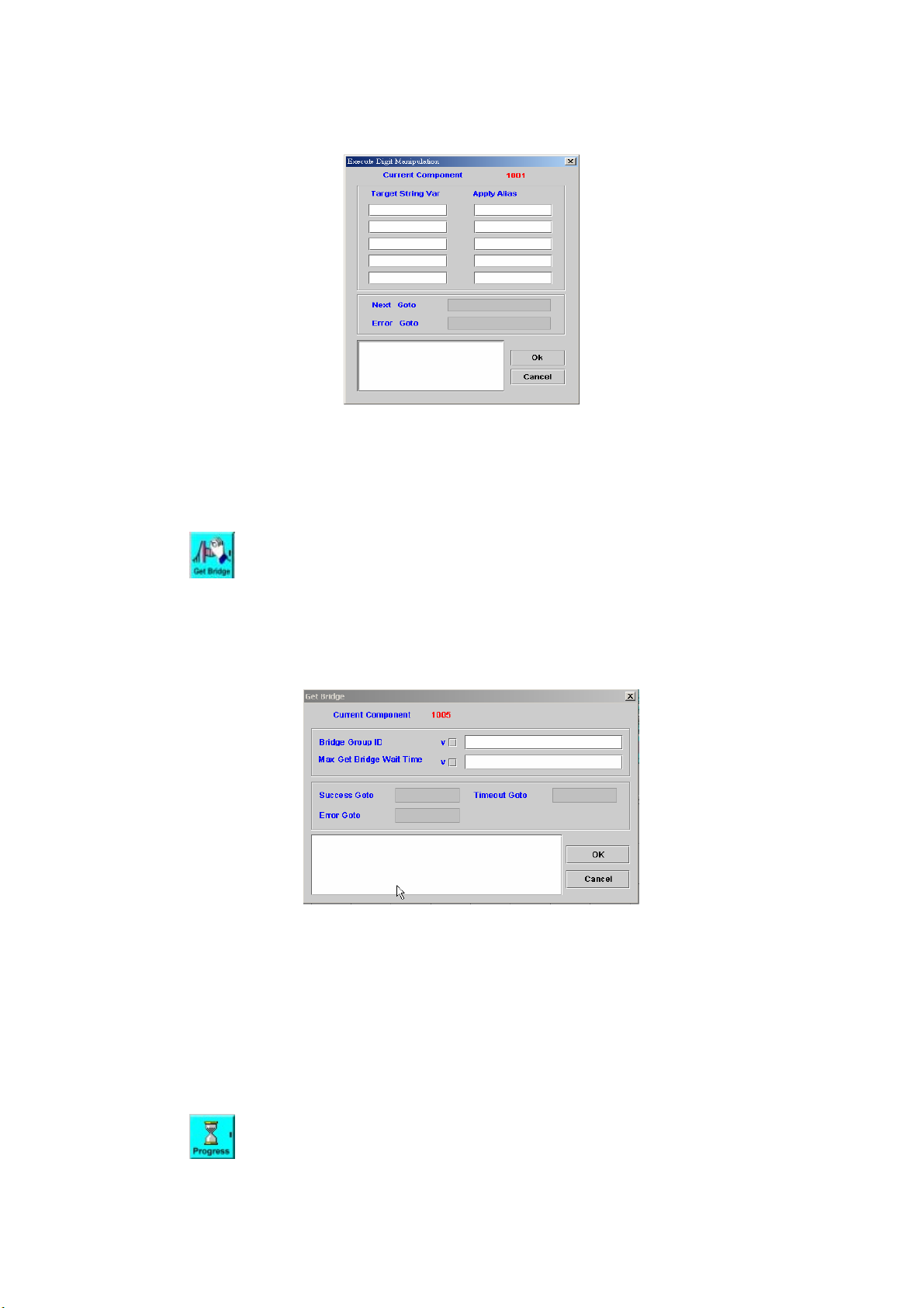
Right-click the Execute Digit Manipulation component, the screen
appears as figure 4-17.
Figure 4-17
Target String Var: The variable to be used for the digit manipulation
Apply Alias: The digit manipulation rule to be used
Next Goto: Next component to be executed if the operation is successful
Error Goto: Next component to be executed if an error is occurred
Remark: Description or remark for this component
4.18 Get Bridge
[Introduction]
The Get Bridge component provides a function to allow the call flow to
check whether a bridge request is arrived (ready) or not.
[Description]
Right-click Get Bridge component, the screen appears as figure 4-18.
Figure 4-18
Bridge Group ID: The bridge group ID to check
Max Get Bridge Wait Time: The maximum waiting time for a bridge request
Success Goto: Next component to be executed if the operation is
successful
Timeout Goto: Next component to be executed if the maximum time is
exceeded.
Error Goto: Next component to be executed if an error is occurred
Remark: Description or remark for this components
4.19 Send Progress
[Introduction]
65
Page 67
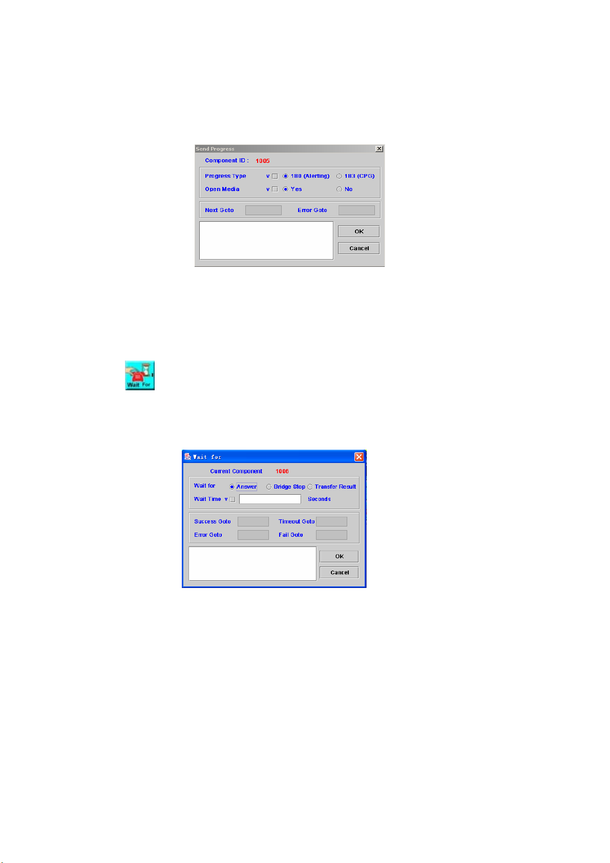
The Send Progress component is used to send SIP call progress
indicator to far end.
[Description]
Right-click the Send Progress component, the screen appears as figure
4-19.
Figure 4-19
Progress Type: The type of progress, 180(Alerting) or 183(CPG)
Open Media: Whether to open the RTP or not (18x SDP)
Next Goto: Next component to be executed if the operation is successful
Error Goto: Next component to be executed if an error is occurred
Remark: Description or remark for this components
4.20 Wait For
[Introduction]
Wait for a specified event such as Answer or Bridge Stop.
[Description]
Right-click Wait For component, the screen appears as Figure 4-20.
Figure 4-20
Wait for: The type of the event waited, answer, and bridge stop or transfer
result. The Wait for “Transfer result” is used for call canter application when
you are using call transfer and the ACD server returning queued state. The
SIPIVR will announce the queued order and waiting time and use Wait for
component to wait ACD transfer result. It is only available for 8680 model.
Wait Time: Max time to wait the event
Success Goto: Next component to be executed if the operation is
successful
Timeout Goto: Next component to be executed if the maximum time is
exceeded.
Error Goto: Next component to be executed if an error is occurred
Fail Goto: Next component to be executed if the operation is fail
Remark: Description or remark for this components
66
Page 68
Chapter 5 Basic Function
5.1 Variable Declaration
[Introduction]
The Variable Declaration component provides a function to declare
variables. Please refer to Appendix D and E for variable type and scope.
[Description]
Right-click Variable Declaration component, the screen appears as
Figure 5.1-1.
Figure 5.1-1
Variable Name: Declare a variable name
Type: Supported variable type
Int: 32-bit integer
Double: 64-bit floating point number
String: string
Password:
String type variable but display it by star sign (i.e.: *) on screen
You must re-type the same secret word to confirm it. The screen
appears as Figure 5.1-2.
Figure 5.1-2
Value: Initial value
Indirect: Check to declare a variable in system based on the variable name
in this component. Please refer to Appendix C for example.
Success Goto: Next component to be executed if the operation is
successful
Error Goto: Next component to be executed if an error is occurred.
Remark: Description or remark for this component.
67
Page 69
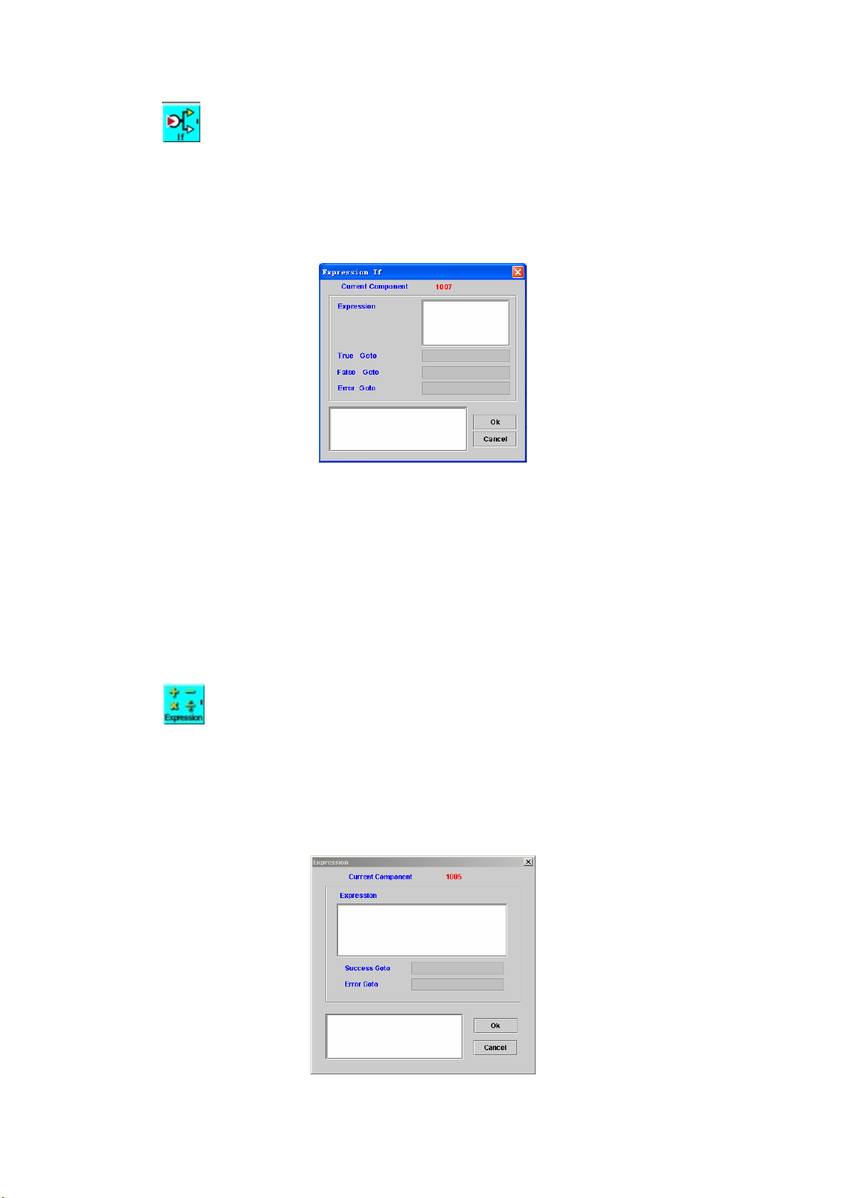
5.2 Expression IF
[Introduction]
The Expression IF component allows the user to test the expression and
decide next to go.
[Description]
Right-click Expression IF component, the Expression IF screen appears
as Figure 5-2.
Figure 5-2
Expression: Expression to be tested. The expression result must be “True”
or “False”. Or error goto will be applied.
True Goto: Next component to be executed if the expression result is
"True"
False Goto: Next component to be executed if the expression result is
"False"
Error Goto: Next component to be executed if an error is occurred
Remark: Description or remark for this component
: Please refer to Appendix B for detail function list of expression.
5.3 Expression
[Introduction]
The Expression component allows user to execute some expression or
assign the value to the variable that predefined by Variable Declaration
component.
[Description]
Right-click Expression component, the screen appears as Figure 5-3.
Figure 5-3
68
Page 70
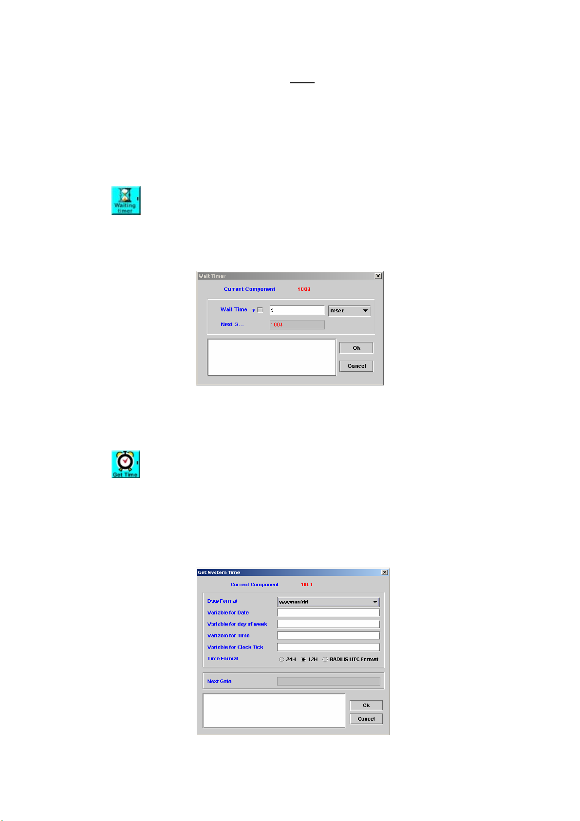
Expression: Write the expression ( Note: One component just can perform
one expression)
Success Goto: Next component to be executed if the expression be
performed correctly
Error Goto: Next component to be executed if an error is occurred
Remark: Description or remark for this component
: Please refer to Appendix B for detail function list of expression.
5.4 Wait Timer
[Introduction]
The Wait Timer component is used to wait for a period.
[Description]
Right-click the Wait Timer component, the screen appears as Figure 5-4.
Figure 5-4
Wait Time: Wait a few mini-seconds
Next Goto: Next component to be executed
Remark: Description or remark for this component.
5.5 Get System Time
[Introduction]
The Get System Time component provides a function to get current
system time.
[Description]
Right-click the Get System Time component, the screen appears as
Figure 5-5.
Figure 5-5
69
Page 71
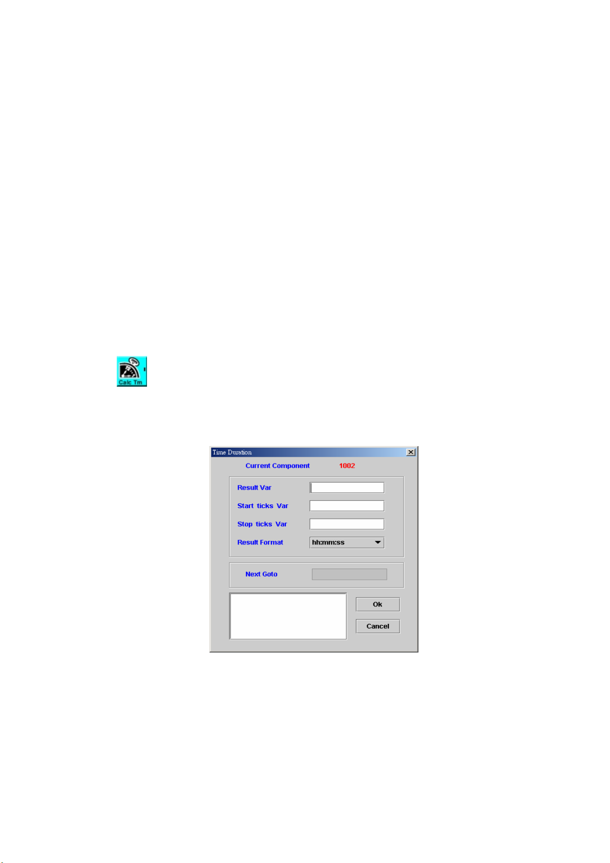
Date Format:
yyyy/mm/dd
mm/dd/yyyy
yy/mm/dd
mm/dd/yy
mm/dd:
dd/mm/yyyy
”dd” is the day (01-31), “mm” is the month (01-12) and “yyyy” is the year.
Variable for Date: String type variable to store current date.
Variable for day of week: Integer type variable to store day. Output value:
Monday is 1, Tuesday is 2 and Sunday is 7.
Variable for Time: String type variable to store current time. Output format :
HH:MM:SS
Variable for Clock Tick: Integer type variable to store system clock tick
which can be used to calculate the time duration in Time Duration
component (Please refer to section 5.6)
Time Format: Select time format (12H, 24H or RADIUS UTC Format) for
output
Next Goto: Next component to be executed
Remark: Description or remark for this component
5.6 Time Duration
[Introduction]
The Time Duration component is used to calculate the time duration.
[Description]
Right-click Time Duration component, the screen appears as Figure 5-6.
Figure 5-6
Result Var: String type variable to store calculated result of time duration
Start ticks Var: A string variable that stored the Start T icks T ime
(Using the Get System Time component to get system tick
time)
Stop ticks Var: A string variable that stored the Stop Ticks Time
(Using the Get System Time component to get system tick
time)
Result Format: Time format to output
70
Page 72
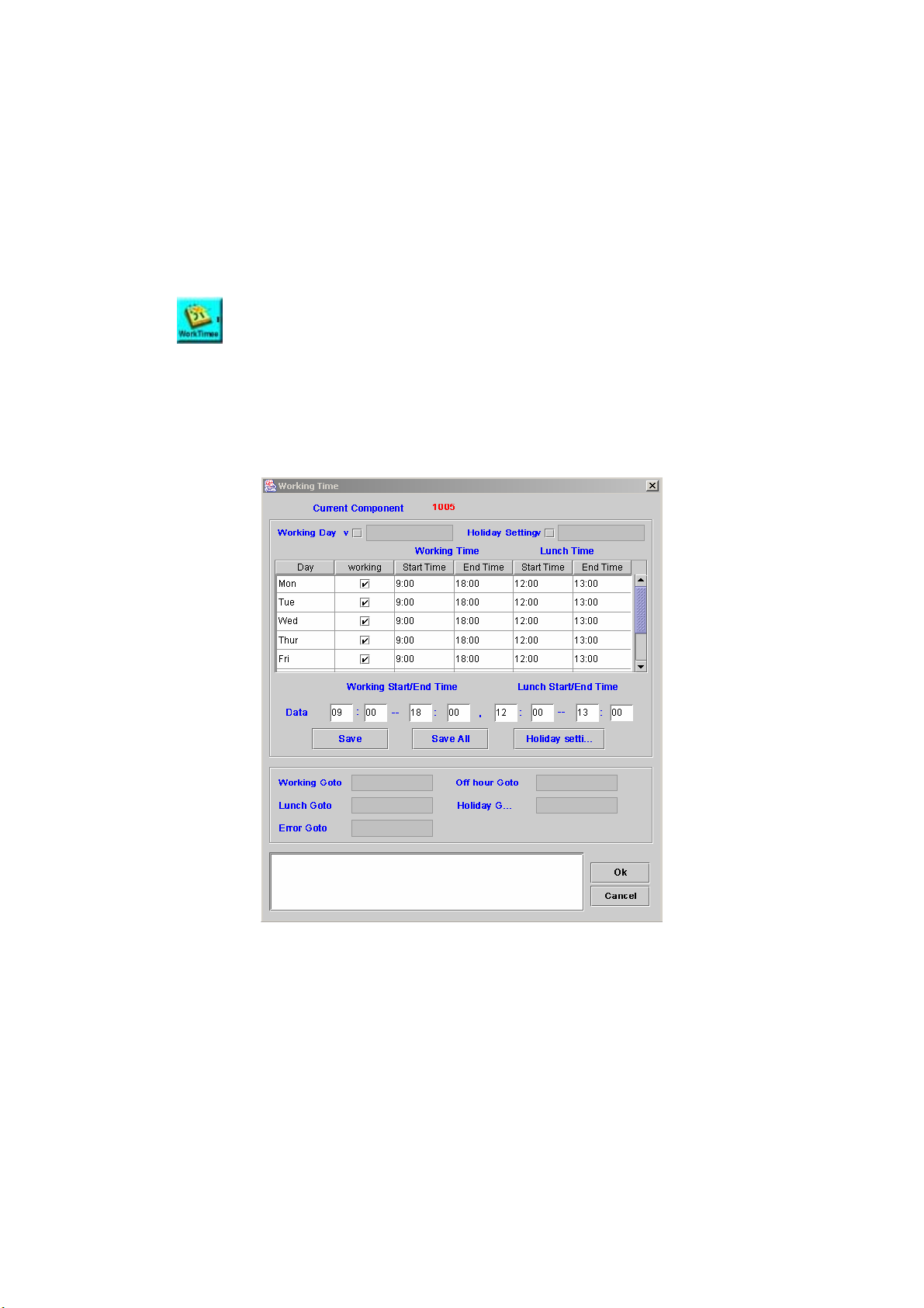
hh:mm:ss ”hh” is the hour (00-23), “mm” is minutes (00-59) and
“ss” is seconds (00-59)
mmmm:ss minutes (0000-9999) and seconds( 00-99 )
ssss all seconds
m:ss minutes ( no limit ) and seconds ( 00-99 )
s.mmm seconds and mini-seconds
Next Goto: Next component to be executed
Remark: Description or remark for this component
5.7 Working Time
[Introduction]
Using Working Time component to decide whether the current time is
working time or not.
[Description]
Right-click the Working Time component, the screen appears as Figure
5.7-1.
Figure 5.7-1
Working Day: Use the assigned working timer for every day
Holiday Setting: Set the holiday
Working Start / End Time: Set the working time in 24-hours format
Lunch Start / End Time: Set the lunch time within the working time
Save: Save single working / lunch time information to the selected day
Save all: Save all changed working and lunch time information
Holiday setting: Click the Holiday setting button to display a screen as
Figure 5.7-2 for Holiday setting:
71
Page 73
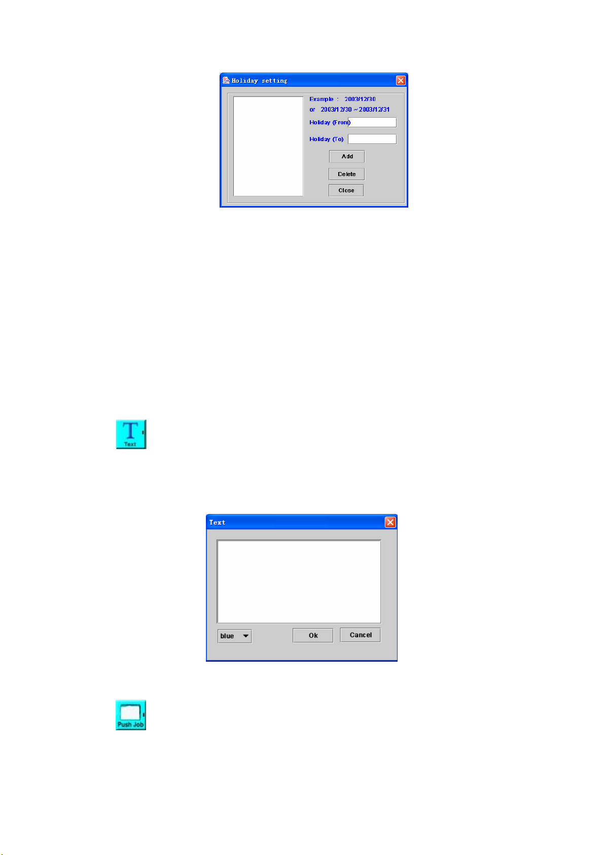
Figure 5.7-2
Holiday ( From ): Start of the holiday (Format: yyyy/mm/dd)
Holiday ( To ): End of the holiday (optional)
Add: Add holiday into list.
Delete: Delete holiday from list.
Close: Close Holiday setting screen.
Working Goto: Next component to be executed when the current time is
working time
Off Hour Goto: Next component to be executed when the current time is
off-hour
Lunch Goto: Next component to be executed when the current time is
lunch time
Holiday Goto: Next component to be executed if today is holiday
Error Goto: Next component to be executed if an error is occurred
Remark: Description or remark for this component.
5.8 Text
[Introduction]
The Text component is used for remark. The text will appear on the
screen at the location where the pointer was when you opened the text input
screen.
Figure 5-8
5.9 Push Job
[Introduction]
The Push Job component allows user to push a job into the job list. The
job will be executed based on job consideration defined in this component.
72
Page 74

Please contact Welltech for JOB server OCX.
[Description]
Right-click the Push Job component, the screen appears as Figure 5-9.
Figure 5-9
Job Group ID: It’s used to identify the job group. Only same group ID
defined in Start component will accept the job request.
Time Format: Choose the time format
Specific Time: Start the job after the specific time (format as
YYYYMMDDHHmm)
Interval Time: Start the job after an interval time (format as
DDHHmm)
Any Time: Start the job immediately
Job Start Time: Set the job starting time if the time formats are Specific or
Interval Time
Max Retry Count: The maximum retry times of the job when the result is
“retry later”.
Retry Interval Time(min): Retry the job after an interval time
Timeout(min): Set the time for canceling the started job
Input Parameters Var: Pass parameters to the channel who get this job
Done Goto: Next component to be executed if the job is pushed
successfully
Fail Goto: Next component to be executed if an error is occurred
Remark: Description or remark for this component
5.10 Job Result
[Introduction]
The Job Result component returns the result of job execution.
[Description]
Right-click the Job Result component, the screen appears as Figure
5-10.
73
Page 75

Figure 5-10
Job Result:
Done: Job success (final state)
Retry Later: Retry this job later (Note: This option is cooperative with
the Max Retry Count and Retry Interval Time in the Push Job
component.)
Fail: Job failure (final state)
Result Variable: Variables returned to external job server.
Next Goto: Next component to be executed
Remark: Description or remark for this component
5.11 Log Message
[Introduction]
The Log Message component provides a function for writing the message
to Log Manager for debug purpose.
[Description]
Right-click the Log Message component, the screen appears as Figure
5-11.
Figure 5-11
Log Level: Set the severity of messages as follows
Critical
Recoverable Critical
User Define Critical
Warning
74
Page 76

Information
User Define
Major Debug
General Debug
Detail Debug
User Define Debug
Log Message: Message to be written to log
Log Variable: Variable and its value to be added for the log
Next Goto: Next component to be executed
5.12 File Operation
[Introduction]
The File Operation component allows user to execute some basic
operations to the file.
[Description]
Right-click the File Operation component, the screen appears as Figure
5-12.
Figure 5-12
Operation Type:
Add File: Add a new file
Copy File: Copy a file
Rename File: Rename a file
Move File: Move a file
Del File: Delete a file
Check exists: Check the file is existed or not
Auto Create Directory: Whether create the directory automatically or not
Overwrite when file exist: Always overwrite the existing file.
Source Directory: The directory of source file
Source Filename: Set the source file to be operated
Destination Directory: The directory of destination file
Destination Filename: Set the destination file to be operated
File Content: file content
Next Goto: Next component to be executed if the operation is successful
Error Goto: Next component to be executed if an error is occurred
75
Page 77

5.13 INI Operation
[Introduction]
The INI Operation component provides a function manipulating the INI file.
[Description]
Right-click the INI Operation component, and there are two modes —
Setting or Getting for discussion as follows.
Case 1) The Operation Type is “Setting”, Figure 5.13-1 shows that.
Figure 5.13-1
Operation Type: “Setting”
Add or update an existing key and value in an INI file. If the target INI file
doesn’t exist, system will create the named INI file before manipulating it.
File Name: INI file name to be created or opened
Section: INI section name
Key: INI parameter Key
Value: INI parameter value
Next Goto: Next component to be executed if the operation successful
Error Goto: Next component to be executed if an error is occurred
Remark: Description or remark for this component
Case 2) The Operation Type is “Getting
”, Figure 5.13-2 shows that.
Figure 5.13-2
Operation Type: Getting
Get key value from INI file
Add Value if Get Failed: Create the new key or session when failed to
read the assigned key. The initial value will be the value of output
76
Page 78

variable.
File Name: INI file name to be created or opened (The INI file be created
by SIPIVR 6800 when file is not found and “Add Value if Get Failed” be
checked)
Section, Key, Variable and Default Value: Get the value of specific
pattern -- <Section, Key, default value> from INI file, and assigned it to
string type Variable
Next Goto: Next component to be executed if the operation successful
Error Goto: Next component to be executed if an error is occurred
Remark: Description or remark for this components
5.14 ID Checking
[Introduction]
The ID Checking component provides Taiwan Company and personal ID
validation.
[Description]
Right-click the ID Checking component, the screen appears as Figure
5-14.
Figure 5-14
Company / Taiwan Personal ID: Select the type of check.
Valid Goto: If validated
Invalid Goto: If failed to validate.
5.15 MD5 Hashing
[Introduction]
The MD5 Hashing component is used to hash any string into a
cryptographic message digest.
[Description]
Right-click the MD5 Hashing component, the screen appears as Figure
5-15.
Figure 5-15
77
Page 79

Source to MD5 Var: The string type variable of source text to be calculated
by MD5
Message Digest Var: The string type variable to be stored the result of
MD5 (message digest)
Next Goto: Next component to be executed
5.16 DES Encode
[Introduction]
The DES Encode component provides a function for converting the plain
text to cipher text, by using the assigned private key.
[Description]
Right-click the DES Encode component, the screen appears as Figure
5-16.
Figure 5-16
Plain Text Var: Set the input plain text variable. (string type)
DES Encoding Key: Set the DES private key
Cypher Text Var: Set the output cypher text variable. (string type)
Use Triple DES Encode: Use triple-DES algorithm to encode plain text to
cypher based on DES Encoding Key
Next Goto: Next component to be executed
Remark: Description or remark for this component
5.17 DES Decode
[Introduction]
The DES Decode component provides a function for decode the
cipher-text to its plain text, by using the assigned DES private key.
[Description]
Right-click the DES Decode component, the screen appears as Figure
5-17.
78
Page 80
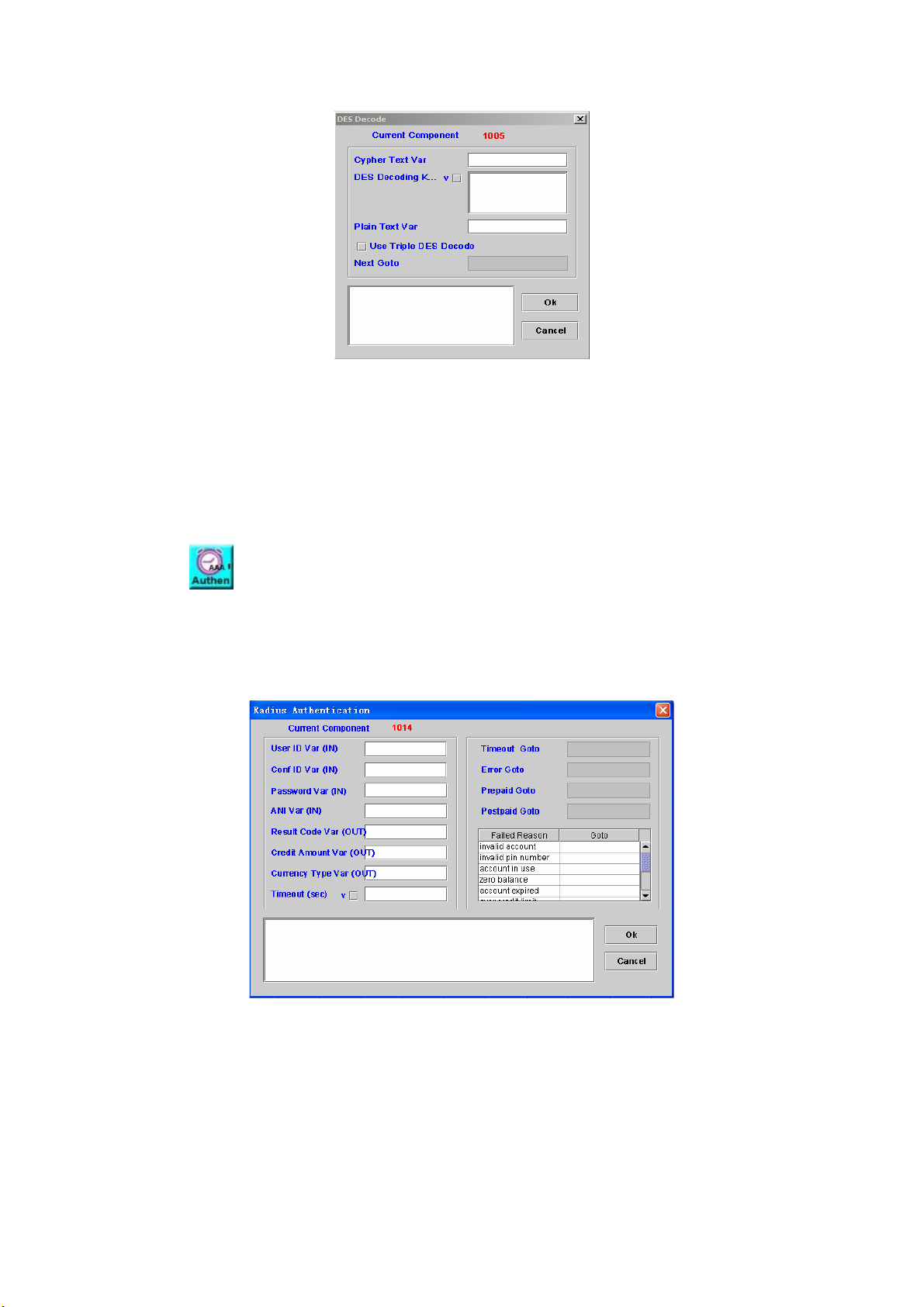
Figure 5-17
Cypher Text Var: Set the input cypher text variable (string type)
DES Decoding Key: Set the DES private key
Plain Text Var: Set the output plain text variable (string type)
Use Triple DES Encode: Use triple-DES algorithm to decode cipher back to
plain text with DES Decoding Key
Next Goto: Next component to be executed
Remark: Description or remark for this component
5.18 Radius Authentication
[Introduction]
Send RADIUS authentication packet to RADIUS Server and wait for result.
[Description]
Right-click the Radius Authentication component, the screen appears as
Figure 5-18.
Figure 5-18
User ID Var (IN): Variable to store user ID
Conference ID Var (IN): Variable to store RADIUS H.323 conference ID
Password Var (IN): Variable to store password
ANI Var (IN): Variable to store calling number
Result Code Var[OUT]: Variable to store called number
Credit Amount Var[OUT]: Variable to store credit amount
Currency Type Var[OUT]: Variable to store currency ( 3-character value
from ISO 4217 )
79
Page 81
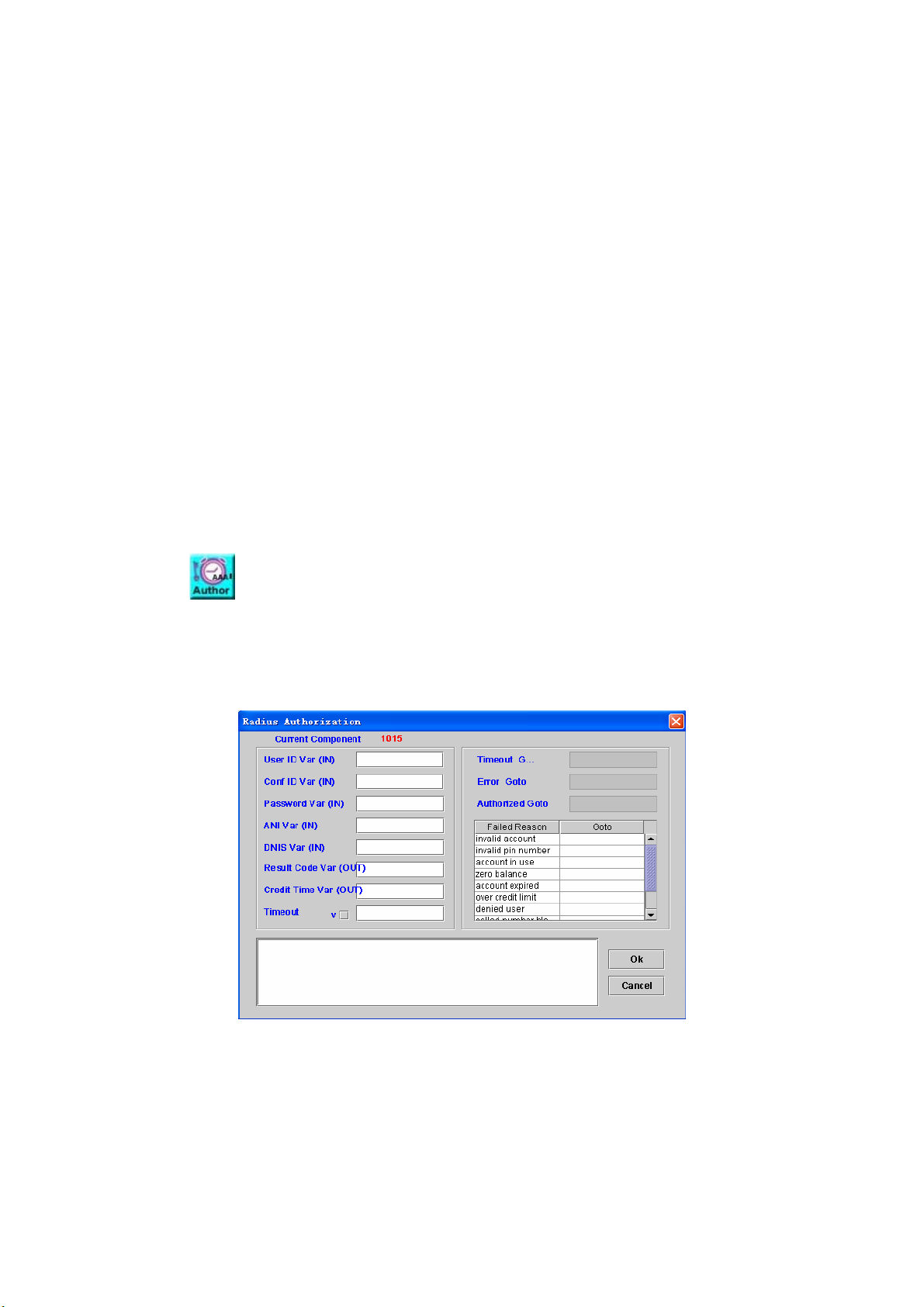
Timeout (sec): The maximum time allow to wait the server response
Timeout Goto: Next component to be executed when failed to receive
response from within timeout period
Error Goto: Next component to be executed if an error is occurred
when the received packet is invalid
Prepaid Goto: Next component to be executed when the account is a
“prepaid” user
Postpaid Goto: Next component to be executed when the account is a
“postpaid” user
Failed Reason:
invalid account
invalid pin number
account in use
zero balance
account expired
over credit limit
denied user
called number blocked
number of retries exceeded
insufficient balance
5.19 Radius Authorization
[Introduction]
Send RADIUS authorization packet to RADIUS Server and wait for result.
[Description]
Right-click the Radius Authorization component, the screen appears as
Figure 5-19.
Figure 5-19
User ID Var (IN): Variable to store user ID
Conference ID Var(IN): Variable to store conference ID
Password Var(IN): Variable to store password
ANI Var(IN): Variable to store calling number
DNIS Var(IN): Variable to store called number
Result Code Var (OUT): Variable to store the result code
Credit Time Var (OUT): Variable to store credit time if success
80
Page 82

Timeout: The maximum time allow wait the server receive
Timeout Goto: Next component to be executed when the server receive
over the maximum time
Error Goto: Next component to be executed if an error is occurred
Authorized Goto: Next component when RAIDUS grant the authority.
Failed Reason:
invalid account
invalid pin number
account in use:
zero balance
account expired
over credit limit
denied user
called number blocked
number of retries exceeded
insufficient balance
5. 20 Accounting Start
[Introduction]
Send Radius accounting start message to RADIUS server for real time
billing.
[Description]
Right-click the Accounting Start component, the screen appears as
Figure 5-20.
Figure 5-20
User ID Var: Variable to store user ID
ANI Var: Variable to store calling number
DNIS Var: Variable to store called number
Service Type:
Login: The user should be connected
Framed: A Framed Protocol should be started for the user
Callback Login: The user should be disconnected and called back,
81
Page 83
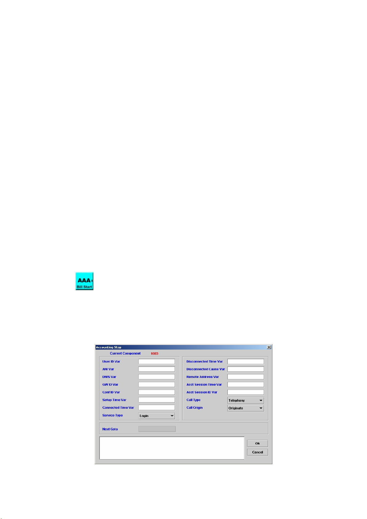
then connected to host
Callback Framed: The user should be disconnected and called back,
then a Framed Protocol should be started for the user
Outbound: The user should be granted access to outgoing devices
Administrative: The user should be granted access to the
administrative interface to the NAS from which privileged commands
can be executed
NAS Prompt: Network access server
Authenticate Only: Only Authentication is requested, and no
authorization information needs to be returned in the Access-Accept
(typically used by proxy servers rather than the NAS itself)
Callback NAS Prompt: The user should be disconnected and called
back, then provided a command prompt on the NAS from which
non-privileged commands can be executed.
GW ID Var: Variable to store gateway ID
Conf ID Var: Variable to store conference ID
Call Type: Protocol type or used on this leg of the call
Telephony
VOIP
Call Origin: The gateway’s behavior in relation to the connection that is
active for this leg
Originate: Call out call leg
Answer: Incoming call leg
Setup Time Var: Variable to store setup time (UTC time format)
Acct Session ID Var: Variable to store Acct Session ID
Next Goto: Next component to be executed
5.21 Accounting Stop
[Introduction]
Send RADIUS accounting stop message to RADIUS server for real time
billing.
[Description]
Right-click Accounting Stop component, the screen appears as Figure
5-21.
Figure 5-21
82
Page 84

User ID Var: Variable to store user ID
ANI Var: Variable to store calling number
DNIS Var: Variable to store called number
GW ID Var: Variable to store gateway ID
Conf ID Var: Variable to store conference ID
Setup Time Var: Variable to store setup time (UTC time format)
Connected Time Var: Variable to store connected time (UTC time format)
Service Type:
Login: The user should be connected
Framed: A Framed Protocol should be started for the user
Callback Login: The user should be disconnected and called back,
then connected to host.
Callback Framed: The user should be disconnected and called back,
and then a Framed Protocol should be started for the user.
Outbound: The user should be granted access to outgoing devices
Administrative: The user should be granted access to the
administrative interface to the NAS from which privileged commands
can be executed.
NAS Prompt: Network access server
Authenticate Only: Only Authentication is requested, and no
authorization information needs to be returned in the Access-Accept
(typically used by proxy servers rather than the NAS itself)
Callback NAS Prompt: The user should be disconnected and called
back, then provided a command prompt on the NAS from which
non-privileged commands can be executed
Disconnected Time Var: Variable to store disconnected time. (UTC time
format)
Disconnected Cause Var: Variable to store disconnected cause.
Remote Address Var: Variable to store remote address
Acct Session Time Var: Variable to store acct session time
Acct Session ID Var: Variable to store Acct Session ID
Call Type: Protocol type or used on this leg of the call
Telephony
VOIP
Call Origin: The gateway’s behavior in relation to the connection that is
active for this leg
Originate
Answer
Next Goto: Next component to be executed
5.22 Send Event
[Introduction]
Send the event and related parameters to the component Wait Event. The
wait event could be on another channel or same channel. The event name
should be same in between Send Event and Wait Event components.
[Description]
Right-click Send Event component, the screen appears as Figure 5-22.
83
Page 85
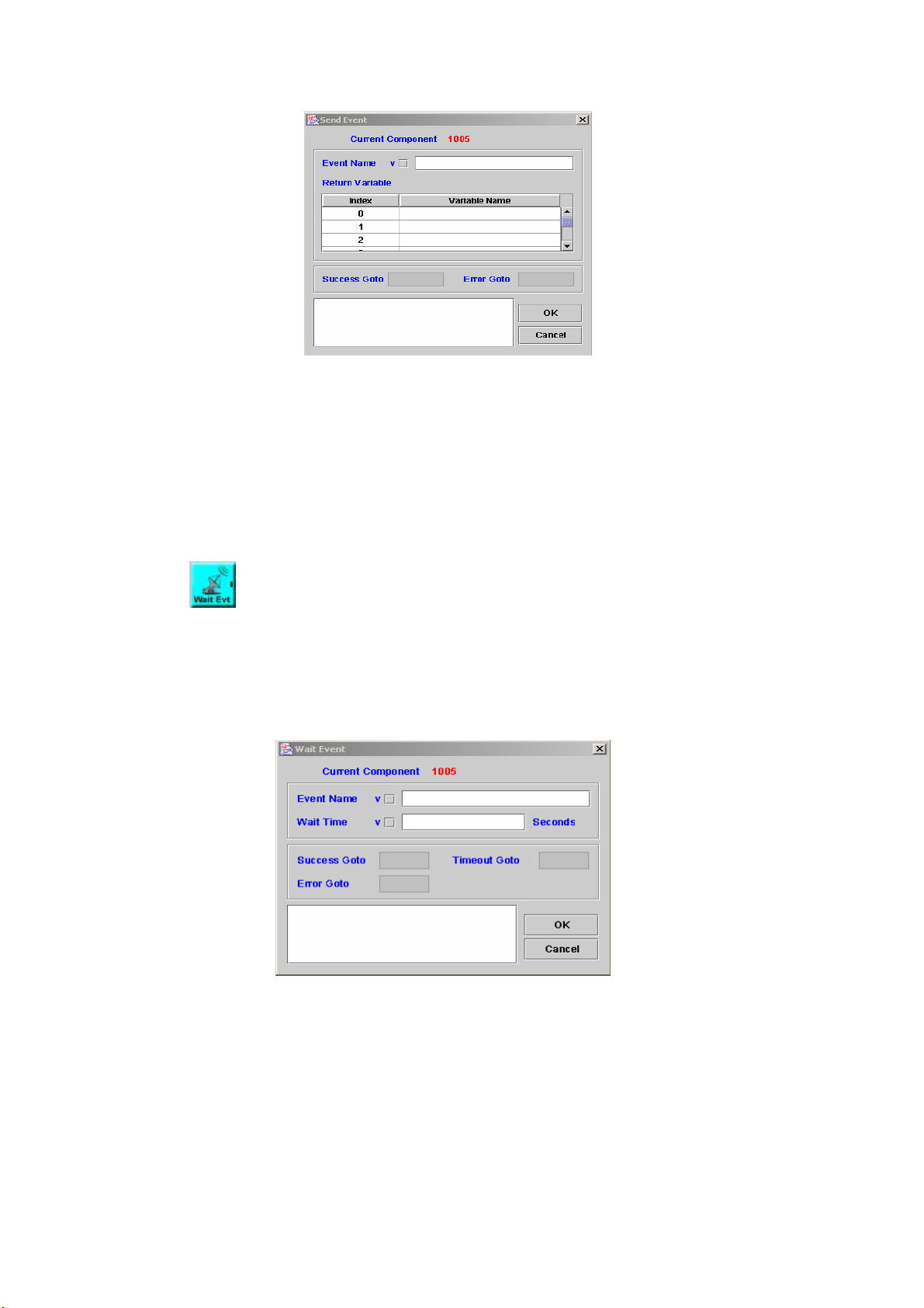
Figure 5-22
Event Name: The name of event will be sent.
Return Variable: Return some variable contents to the channels which
received the event.
Index: The variable ID
Variable Name: The name of variable
Success Goto: Next component to be executed if the operation successful
Error Goto: Next component to be executed if an error is occurred
Remark: Description or remark for this components
5.23 Wait Event
[Introduction]
Wait to receive the event and relative parameters sent by other channels
or Call Flow. It appears with Send Event concurrently.
[Description]
Right-click the Wait Event component, the screen appears as Figure
5-23.
Figure 5-23
Event Name: The name of event that waits to receive.
Wait Time: Wait a few mini-seconds
Success Goto: Next component to be executed if the operation is
successful
Timeout Goto: Next component to be executed if the maximum time is
exceeded.
Error Goto: Next component to be executed if an error is occurred
Remark: Description or remark for this components
84
Page 86
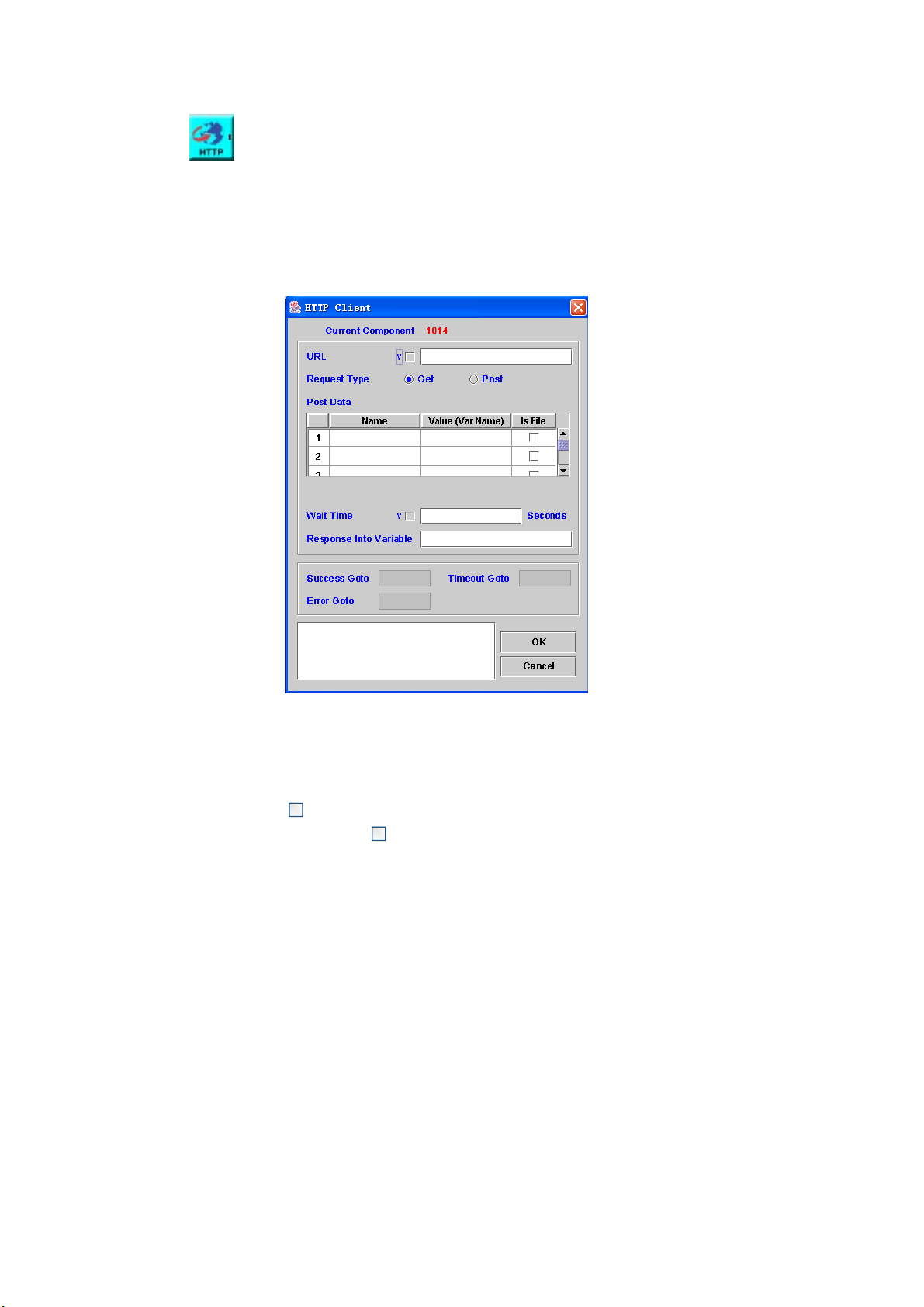
5.24 HTTP Client
[Introduction]
Execute an HTTP request and store the returned result in the assigned
variable.
[Description]
Right-click the HTTP Client component, the screen appears as Figure
5-24.
Figure 5-24
URL: Universal Resource Location.
Request Type: HTTP Request method, the default value is Get.
Name: The maximum length is 20.
Value (Var Name): The maximum length is 20.
Is File: If
the method is Get,
is selected, the variable name will be the file name. When
should be disable.
Post Data: The data for post (Name, Value and Is File or not)
Wait Time: The maximum time to wait the HTTP result
Response Into Variable: The variable the HTTP result is stored.
Success Goto: Next component to be executed if the operation successful
Timeout Goto: Next component to be executed if the maximum time is
exceeded.
Error Goto: Next component to be executed if an error is occurred
Remark: Description or remark for this components
The http code page need be defined in the START component.
85
Page 87
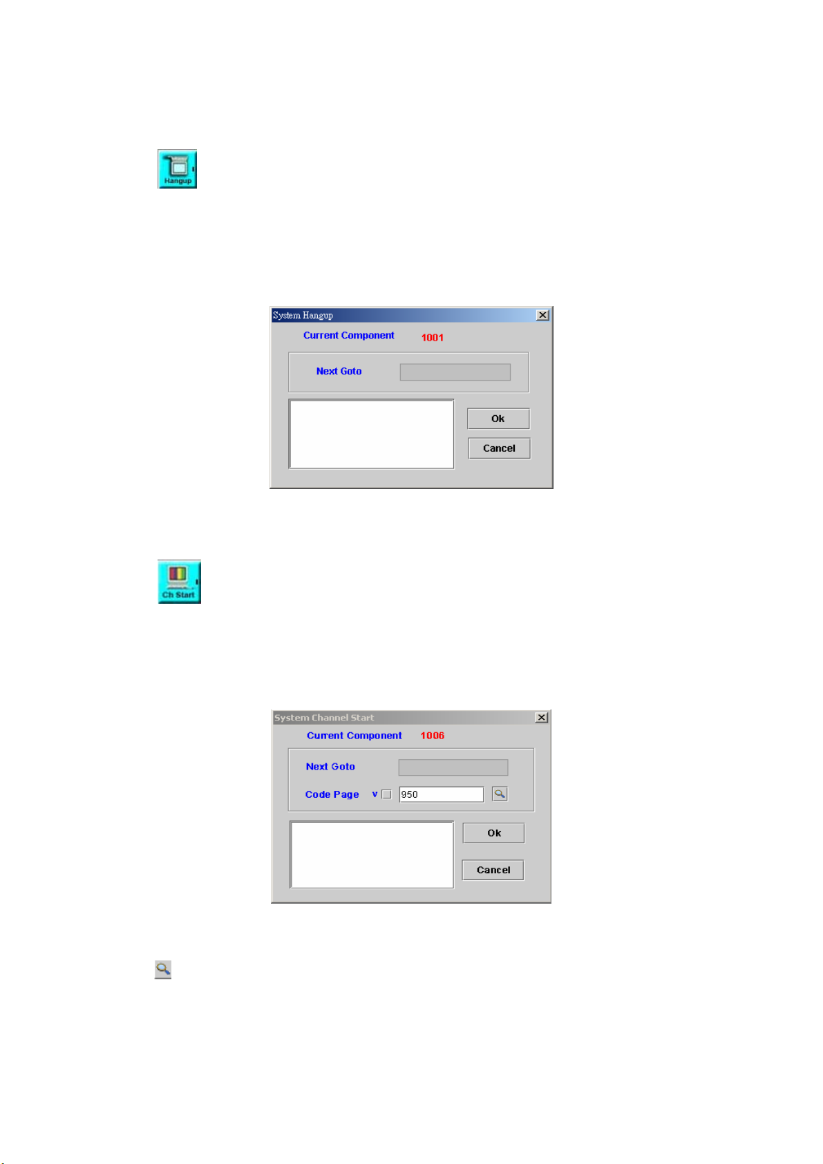
Chapter 6 Flow Control Function
6.1 System Hangup
[Introduction]
When the caller hangs up, system will jump to this system hang up flow.
All IVR related components to be handled based as success to next.
[Description]
Right-click the System Hangup component, the screen appears as Figure
6-1.
Figure 6-1
Next Goto: Next component to be executed
Remark: Description or remark for this component
6.2 System Channel Start
[Introduction]
The system will execute this component when the channel is started.
[Description]
Right-click the System Channel Start component, the screen appears as
figure 6-2.
Figure 6-2
Next Goto: Next component to be executed
Code Page: The page that the code belonged to.
Remark: Description or remark for this component
: Display the Code Page list.
86
Page 88
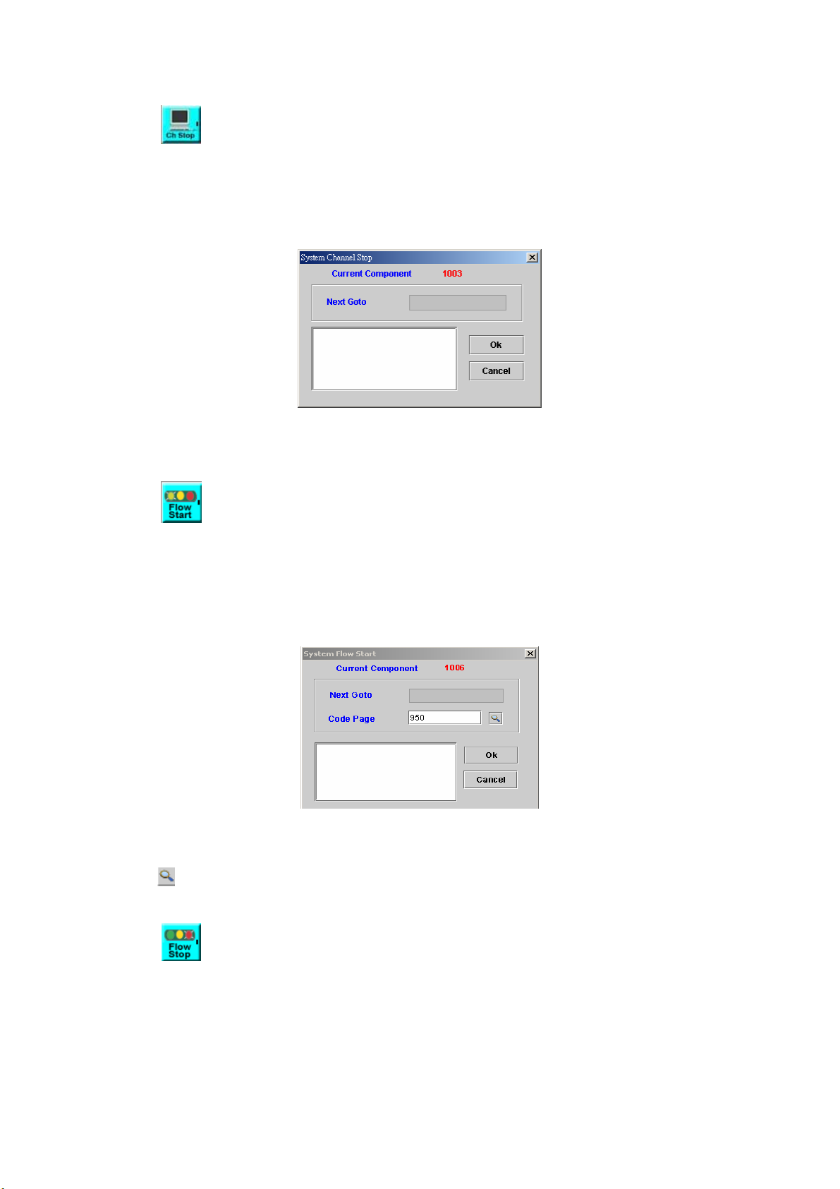
6.3 System Channel Stop
[Introduction]
The system will execute this component when the channel is stopped.
[Description]
Right-click the System Channel Stop component, the screen appears as
Figure 6-3.
Figure 6-3
Next Goto: Next component to be executed
Remark: Description or remark for this component
6.4 System Flow Start
[Introduction]
The system will execute this component when the call flow is started. It will
be run once only when first call flow is loaded.
[Description]
Right-click the System Flow Start component, the screen appears as
Figure 6-4.
Figure 6-4
Next Goto: Next component to be executed
Code Page: The page that the code belonged to.
Remark: Description or remark for this component
: Display the Code Page list.
6.5 System Flow Stop
[Introduction]
The system will execute this component when the call flow is stopped. It
will be run once only when last call flow is unloaded.
[Description]
Right-click the System Flow Stop component, the screen appears as
Figure 6-5.
87
Page 89
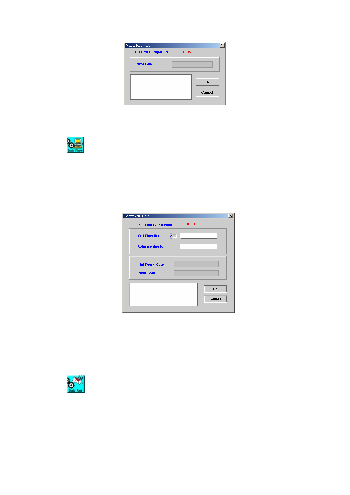
Figure 6-5
Next Goto: Next component to be executed
Remark: Description or remark for this component
6.6 Execute Sub-Flow
[Introduction]
This function is used to execute a sub-flow. All variable can be seen in sub
flow. After return from sub-flow by the sub-flow return, the return value can be
used to indicate the execution result.
[Description]
Right-click the Execute Sub-Flow component, the screen appears as
Figure 6-6.
Figure 6-6
Call Flow Name: Sub flow name to be called
Return Value: Sub flow return value
Not Found Goto: Next component to be executed if the sub-flow is not
found
Next Goto: Next component to be executed if the operation is successful
Remark: Description or remark for this component
6.7 Sub-Flow Return
[Introduction]
This component is used together with Execute Sub-Flow as a pair, to quit
the sub-flow and go back to the upper (calling) call flow.
[Description]
Right-click the Sub-Flow Return component, the screen appears as
Figure 6-7.
88
Page 90

Figure 6-7
Return Value: A Return value of the sub-flow to main flow
Remark: Description or remark for this component
6.8 Conditional Case
[Introduction]
The Conditional Case component allows the user to go to different flow
based on input value.
[Description]
Right-click the Conditional Case component, the Conditional Case
screen appears as Figure 6-8.
Figure 6-8
Variable Name: Source variable to be used for comparison.
String Value: Compared value
Case Goto: Next component to be executed if source variable value is
equal to string value
Default Goto: Next component to be executed if not matched
Remark: Description or remark for this component.
6.9 Go To
[Introduction]
The Go To component is used to go directly to the specified component.
[Description]
Right-click the Go To component, the screen appears as Figure 6-9.
89
Page 91
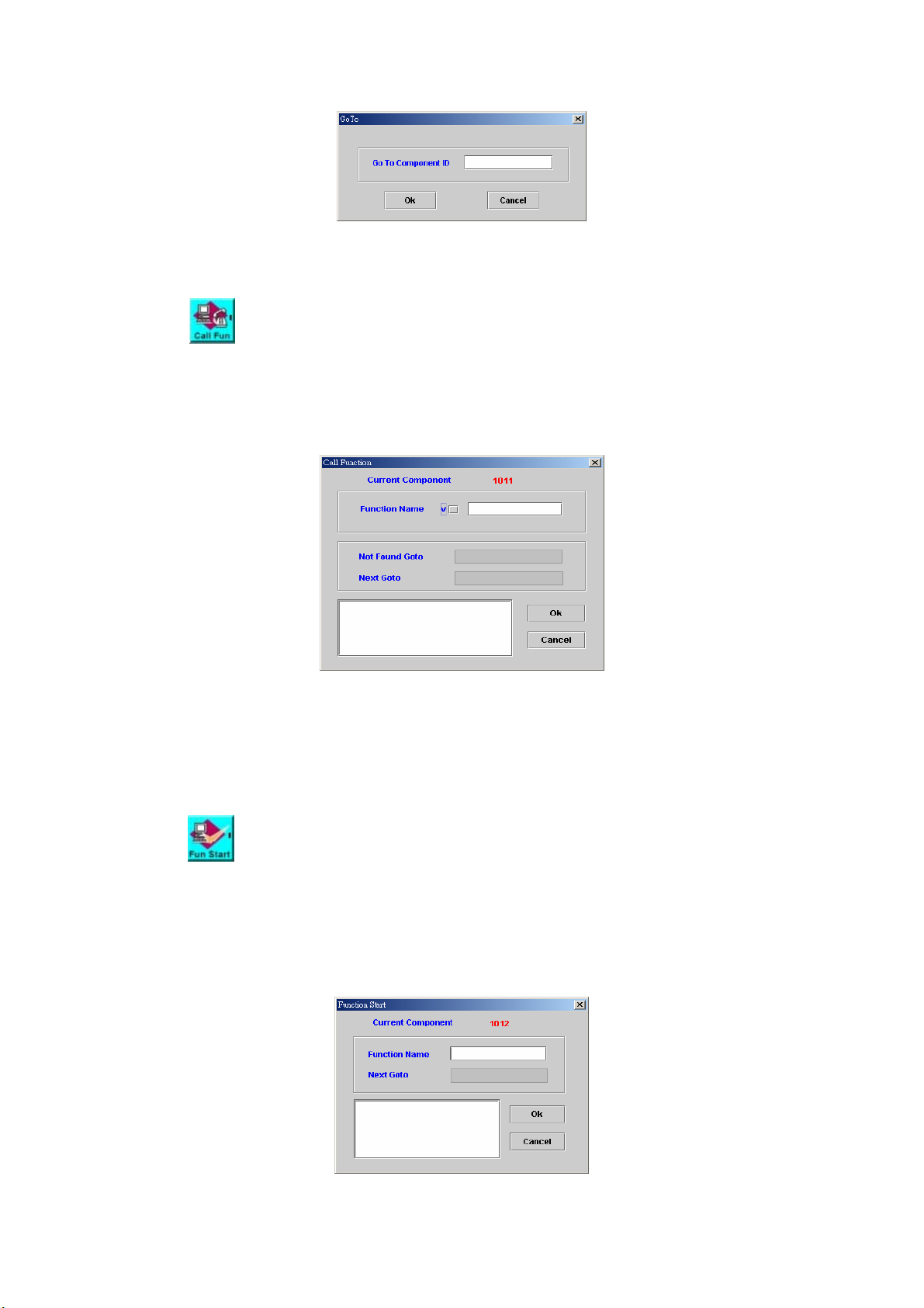
Figure 6-9
Go To Component ID: Jumped component ID
Remark: Description or remark for this component.
6.10 Call Function
[Introduction]
This component is used to execute a function in the same call flow.
[Description]
Right-click the Call Function component, the screen appears as Figure
6-10.
Figure 6-10
Function Name: Function name to be called in the same call flow
Not Found Goto: Next component to be executed when function is not
found
Next Goto: Next component to be executed if the operation is successful
Remark: Description or remark for this component
6.11 Function Start
[Introduction]
Function Start component needs work with Function End to identify a
function call in the same call flow.
[Description]
Right-click the Function Start component, the screen appears as Figure
6-11.
Figure 6-11
90
Page 92

Function Name: Function name for identification
Next Goto: Next component to be executed
Remark: Description or remark for this component
6.12 Function End
[Introduction]
End definition of sub-function.
[Description]
Right-click the Function End component, the screen appears as Figure
6-12.
Figure 6-12
Remark: Description or remark for this component
6.13 Hook
[Introduction]
The Hook component allows call flow to call an external subroutine based
on C programming language over network or on local host. The hook server
needs to be defined by system configuration. A special local hook or on local
host can be used for local hook in the same system. User need to write its own
syshook.exe to make local hook working. Please contact Welltech for HOOK
Server OCX.
[Description]
Right-click the Hook component, the screen appears as Figure 6-13.
Figure 6-13
91
Page 93

Hook IP: The hook server IP
Hook ID: This field indicates which hook routine within the hook server to
be executed
Timeout Time(sec): The maximum of time to allow this hook to be executed
Wait forever: Check this box, the system will wait infinitely until hook
finished
Variable:
Index: Variable index
Variable Name: Variables to be pass to hook server
Success Goto: Next component to be executed when the operation is
successful.
Error Goto: Next component to be executed when error occurred.
Remark: Description or remark for this component
6.14 Quit
[Introduction]
Stop the current operation and quit.
[Description]
Right-click the Quit component, the screen appears as Figure 6-14.
Figure 6-14
Remark: Description or remark for this component
6.15 UnInterrupt Call Begin
[Introduction]
UnInterrupt Call Begin needs work with UnInterrupt Call End to protect
the integrality of components in between, even caller hangs up. It can be used
to make sure the component within UnInterrupt Call Begin and UnInterrupt
Call End to be executed completely even the call is disconnect. For those
components need IVR within protect area will be handled as success to next.
[Description]
Right-click the UnInterrupt Call Begin component, the screen appears as
Figure 6-15.
Figure 6-15
92
Page 94

Next Goto: Next component to be executed
Remark: Description or remark for this component
6.16 UnInterrupt Call End
[Introduction]
UnInterrupt Call End needs work with UnInterrupt Call Begin to protect
the integrality of components in between, even caller hangs up. It can be used
to make sure the components within UnInterrupt Call Begin and UnInterrupt
Call End to be executed completely even the call is disconnect. For IVR related
components within protect area to be handled as success to next.
[Description]
Right-click the UnInterrupt Call End components, the screen appears as
Figure 6-16.
Figure 6-16
Next Goto: Next component to be executed
Remark: Description or remark for this component
93
Page 95

Chapter 7 Database Function
7.1 Database Connect
[Introduction]
Create a database connection to DB server. The system will manage the
connection pool to improve the overall performance.
[Description]
Right-click the Database Connect component, the screen appears as
Figure 7-1.
Figure 7-1
Alias Name: Used to identify a DB connection
User ID: The login ID account name for accessing the DB
Password: The password for accessing the DB
Time out (sec): The max time to wait to connect to DB. It is calculated after
got a free DB connection from connection pool.
Get Resource Timeout (sec): The max time to wait for getting a free
connection resource. SIP6800 will manage the DB connection pool (max is
64 connections) to improve overall performance. User can change it on
system configuration.
Wait Forever: Check this box, the system will wait infinitely until getting
connection resource
Connection String: Information for connection to DB server. ( Server name
in Connection String must be in IP format )
Filename: Check “Filename” and set the file path if you want to use a
“udl” file (Microsoft Universal Data Link) to connect with DB.
Var: Check "Var" when “Connection String” is stored in a variable
Success Goto: This read-only field contains the component ID that takes
control following successful completion of the current component
Error Goto: Next component to be executed if an error is occurred
Timeout Goto: Next component to be executed if waiting DB response time
out
94
Page 96
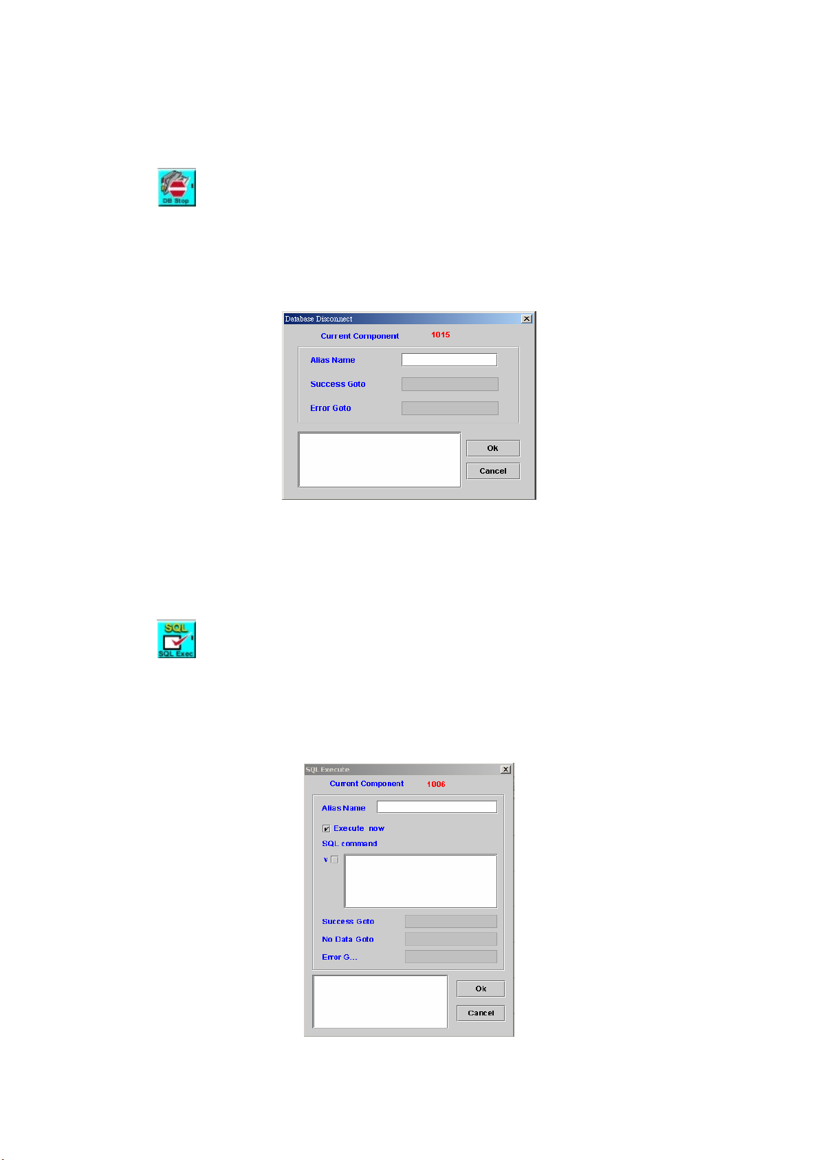
No Resource Goto: Next component to be executed if waiting connection
resource time out
Remark: Description or remark for this component
7.2 Database Disconnect
[Introduction]
Disconnect the database connection. It will only free the resource for other
requests. SIPIVR 6800 will handle the connection pool by itself.
[Description]
Right-click DB Disconnect component, the screen appears as Figure 7-2.
Figure 7-2
Alias Name: Used to identify a DB connection
Success Goto: This read-only field contains the component ID that takes
control following successful completion of the current component.
Error Goto: Next component to be executed if an error is occurred.
Remark: Description or remark for this component.
7.3 SQL Execute
[Introduction]
Execute a SQL command. User has to define the output variable mapping
by using “Field Mapping” component for those SQL selection statements.
[Description]
Right-click SQL Execute component, the screen appears as Figure 7-3.
Figure 7-3
95
Page 97
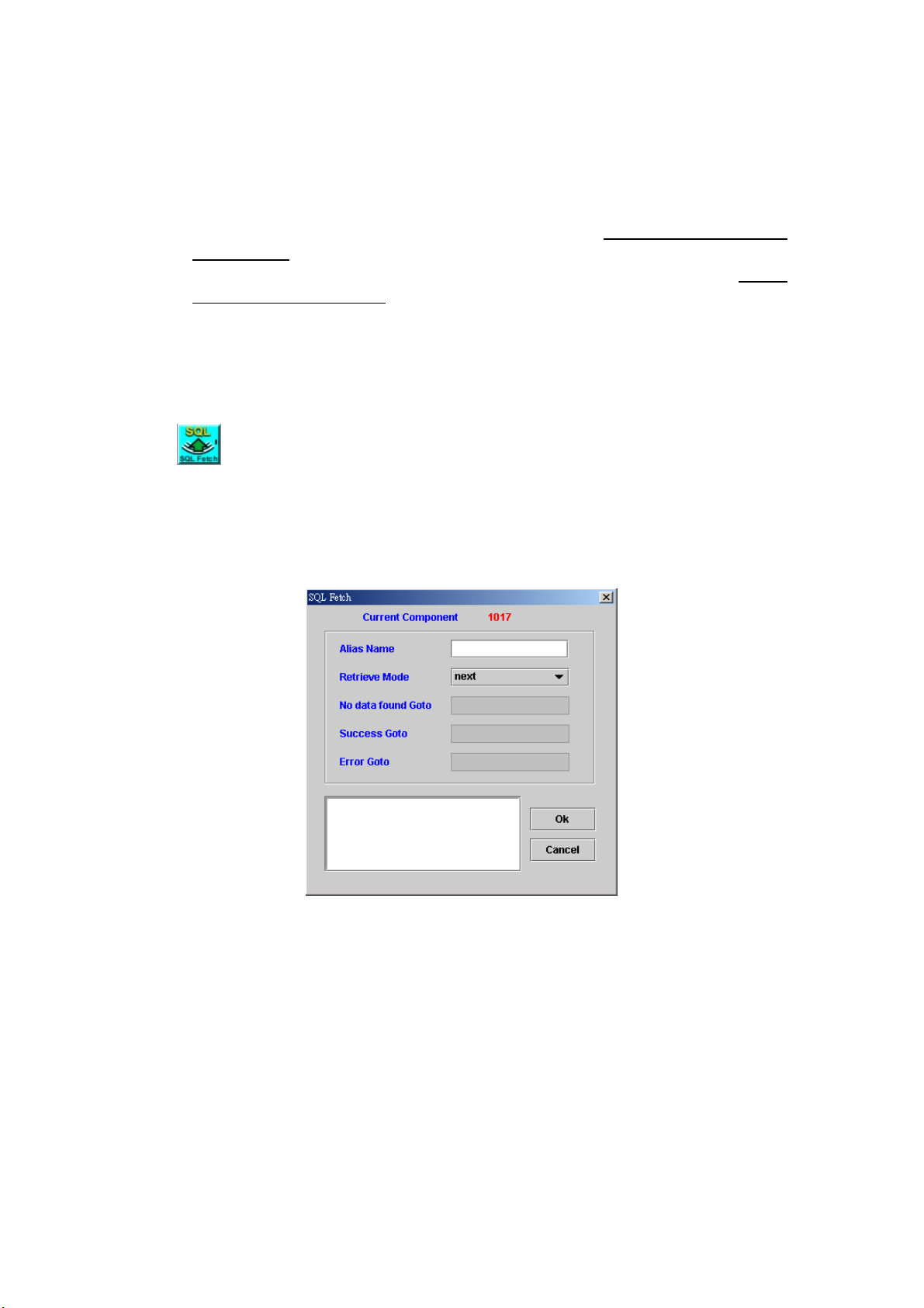
Alias Name: Used to identify a DB connection
Execute Now: Check this box, the SQL Command will execute
immediately
SQL Command: SQL Command. “$$” is a reserved word. It is used as a
pair to indicate it is a variable instead of value. For example, you declare
a variable: var_1=“Filed1” at first. When you type “select $$var_1$$ from
some Table” in SQL Command field, the system replace $$var_1$$ to
“Field1”. Thus the inputted SQL Command will be translated to “select
Field1 from some Table”.
Success Goto: This read-only field contains the component ID that takes
control following successful completion of the current component
Not data Goto: Next component to be executed if no data found
Error Goto: Next component to be executed if an error is occurred
Remark: Description or remark for this component
7.4 SQL Fetch
[Introduction]
Retrieve data from database cursor. The output field is defined by SQL
Execution and Filed Mapping components.
[Description]
Right-click the SQL Fetch component, the screen appears as Figure 7-4.
Figure 7-4
Alias Name: Used to identify a DB connection
Retrieve Mode:
next: Fetch the next row of the result set
first: Fetch the first row of the result set
prior: Fetch the prior row of the result set
last: Fetch the last row of the result set
No Data found Goto: Next component to be executed if no data found
Success Goto: This read-only field contains the component ID that takes
control following successful completion of the current component
Error Goto: Next component to be executed if an error is occurred
Remark: Description or remark for this component
96
Page 98
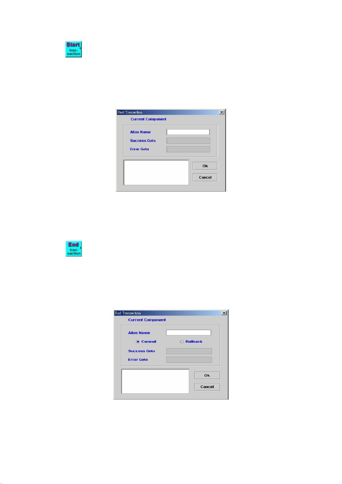
7.5 Start transaction
[Introduction]
Start transaction need work with End transaction. Start Transaction
and End Transaction functions work together to protect the DB integration.
[Description]
Right-click the Start transaction component, the screen appears as
Figure 7-5.
Figure 7-5
Alias Name: Used to identify a DB connection
Success Goto: This read-only field contains the component ID that takes
control following successful completion of the current component
Error Goto: Next component to be executed if an error is occurred
Remark: Description or remark for this component
7.6 End transaction
[Introduction]
End transaction needs work with Start transaction. The End
Transaction gives the option to commit or roll back the DB changes.
[Description]
Right-click the End transaction component, the screen appears as
Figure 7-6.
Figure 7-6
Alias Name: Used to identify a DB connection
Commit: To make permanent changes to data (inserts, updates, deletes)
in the database.
Rollback: Roll back to the original data.
97
Page 99
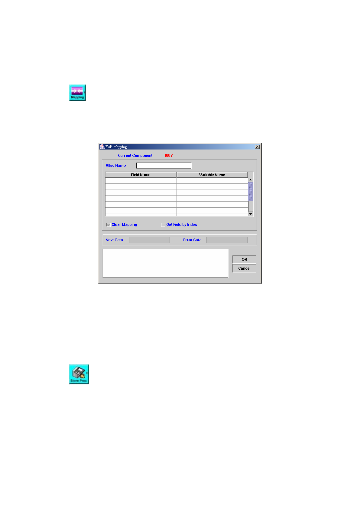
Success Goto: This read-only field contains the component ID that takes
control following successful completion of the current component
Error Goto: Next component to be executed if an error is occurred
Remark: Description or remark for this component
7.7 Field Mapping
[Introduction]
Map SQL execution result (i.e.: record) into the defined variables.
[Description]
Right-click Field Mapping component, the screen appears as Figure 7-7.
Figure 7-7
Alias Name: Used to identify a DB connection
Field Name: Field name in DB
Variable Name: The variable that will store the fetched result
Clear Mapping: Clear the field mapping buffer
Get Field by Index: Check to use the field index instead of DB field
Next Goto: Next component to be executed if the operation is successful
Error Goto: Next component to be executed if an error is occurred
Remark: Description or remark for this component.
7.8 Store procedure
[Introduction]
Store procedure component is used to execute a stored procedure in
database server.
[Description]
Right-click the Field Mapping component, the screen appears as Figure
7-8.
98
Page 100
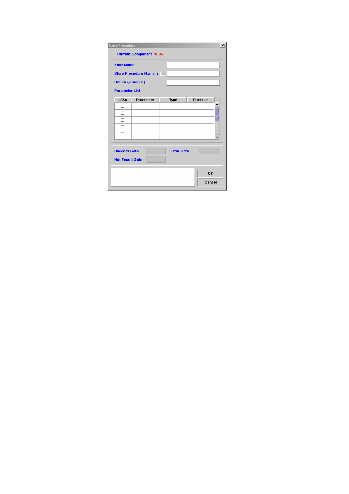
Figure 7-8
Alias Name: Used to identify a DB connection
Store Procedure Name: The name used for storing the procedure.
Return (variable): Stored procedure execute result
Parameter List:
Is Var: Check “Is Var” box to indicate that the message string is a
variable name
Type: the type of the parameter selected.
Direction: The instruction of the procedure.
Success Goto: Next component to be executed if the operation
successful
Error Goto: Next component to be executed if an error is occurred
Not Found Goto: Next component to be executed when function is not
found
Remark: Description or remark for this component.
99
 Loading...