


SII
S
U
s
U
P
P
err’’
s
P
P
e
B
B
s
s
X
X
6
M
M
6
a
a
2
2
n
n
0
0
u
u
0
0
all
A
A
a
Version: SIPPBXUM.101

CH1. Overview..................................................................................- 5 -
1.1 Specifications ............................................................................................. - 5 -
1.2 Hardware Overview.................................................................................. - 8 -
1.2.1 The Front Panel ...................................................................................... - 8 -
1.2.2 The Back Panel....................................................................................... - 8 -
CH2. Start to configure SIPPBX 6200A................................- 10 -
2.1 Connection SIPPBX 6200A .................................................................. - 10 -
2.1.1 Network Configuration.........................................................................- 11 -
2.1.2 Extension Configuration ..................................................................... - 14 -
2.1.3 Trunk Configuration............................................................................. - 19 -
CH3. Full Web Configurations ..................................................- 23 -
3.1 Configuration............................................................................................ - 25 -
3.1.1 IP PBX .................................................................................................... - 25 -
3.1.2 Office Call Rule ..................................................................................... - 30 -
3.1.3 Feature Code ........................................................................................ - 33 -
3.1.4 Extension............................................................................................... - 37 -
3.1.5 Auto COnfig (IPv4) .............................................................................. - 45 -
3.1.6 Trunk ...................................................................................................... - 51 -
3.1.7 SIP Trunk Reg....................................................................................... - 56 -
3.1.8 Outgoing Routing................................................................................. - 59 -
3.1.9 Incoming Call Rule............................................................................... - 64 -
3.1.10 Dial Group.......................................................................................... - 67 -
3.1.11 Speed Dial ......................................................................................... - 69 -
3.1.12 Broadcast........................................................................................... - 71 -
3.1.13 Meetme Conf..................................................................................... - 73 -
3.1.14 T.38 FAX ............................................................................................. - 75 -
3.2 Information............................................................................................... - 76 -
3.2.1 Subscriber Info..................................................................................... - 76 -
3.2.2 Call Monitor........................................................................................... - 77 -
3.2.3 CDR ........................................................................................................ - 79 -
3.2.4 System Info .......................................................................................... - 81 -
3.3 Network ...................................................................................................... - 82 -
3.3.1 Network ................................................................................................. - 82 -
3.3.2 DHCP Srv. (IPv4) ................................................................................. - 85 -
3.3.3 DDNS Srv. (IPv4)................................................................................. - 86 -
3.4 Management ............................................................................................. - 87 -
- 2 -

3.4.1 Time Setting ......................................................................................... - 87 -
3.4.2 SMTP Setting ........................................................................................ - 89 -
3.4.3 VM Setting............................................................................................. - 90 -
3.4.4 Security.................................................................................................. - 92 -
3.4.5 Firmware Upload.................................................................................. - 94 -
3.4.6 Music Upload......................................................................................... - 95 -
3.4.7 Import Setting...................................................................................... - 96 -
3.4.8 Export Setting ...................................................................................... - 97 -
3.4.9 Rest To Default ..................................................................................... - 98 -
3.4.10 Reboot System.................................................................................. - 98 -
3.4.11 Power Off System............................................................................. - 98 -
CH4. Application Setting............................................................- 99 -
4.1 Customize System prompt................................................................... - 99 -
4.1.1 Record Greeting ................................................................................... - 99 -
4.1.2 Enable Automated Attendant ............................................................ - 99 -
4.1.3 How to record the other System Prompts ...................................... - 99 -
4.2 Customize Ring Back Tone (Transferring Tone) ........................- 114 -
4.3 Call Features............................................................................................- 115 -
4.3.1 Authentication .....................................................................................- 115 -
4.3.2 Automated Attendant.........................................................................- 115 -
4.3.3 Call Transfer.........................................................................................- 115 -
4.3.4 Blind Transfer.......................................................................................- 115 -
4.3.5 Call Forward on Busy .........................................................................- 115 -
4.3.6 Call Forward on No Answer...............................................................- 115 -
4.3.7 Call Forward Unconditional ...............................................................- 115 -
4.3.8 Call Forward Unavailable ...................................................................- 116 -
4.3.9 Call Hold/Retrieval (Client based) ...................................................- 116 -
4.3.10 Call Routing ......................................................................................- 116 -
4.3.11 Call Waiting (Client based)............................................................- 116 -
4.3.12 Caller ID............................................................................................- 116 -
4.3.13 CLIR (Caller Line Identification Restriction)...............................- 116 -
4.3.14 Do Not Disturb (Client based) ......................................................- 117 -
4.3.15 Flexible Extension Logic.................................................................- 117 -
4.3.16 Music On Hold ..................................................................................- 117 -
4.3.17 Music On Transfer............................................................................- 117 -
4.3.18 Call Pickup ........................................................................................- 117 -
4.3.19 Call Park............................................................................................- 117 -
4.3.20 Camp-On (Call Back on Busy) ......................................................- 117 -
4.3.21 Meetme Conference........................................................................- 118 -
- 3 -

4.3.22 Broadcast..........................................................................................- 118 -
4.3.23 Time and Date .................................................................................- 118 -
4.3.24 Trunk (WG2680)..............................................................................- 118 -
4.3.25 VoIP Gateways (WG2680; WG2504)...........................................- 118 -
4.3.26 Voice Mail to e-mail ........................................................................- 118 -
4.3.27 Access Voice Mail by phone set....................................................- 118 -
4.3.28 Call Monitor ......................................................................................- 118 -
CH5. Appendix.............................................................................. - 119 -
5.1 Voice Mail System Concept.................................................................- 119 -
5.2 System Prompts (Chinese)................................................................ - 122 -
- 4 -

CH1. Overview
SIPPBX 6200A IP-PBX is an IP based IP-PBX which including legend digital PABX
telephony services, Auto Attendant, Voice Mail, Music Ring Back Tone, Conference and
Announcement features together. It also works on both IPv6 and IPv4 network address
simultaneously, which makes migration from IPv4 to IPv6 network smoothly.
SIPPBX 6200A is not only an IP-PBX, but also an efficient communication tool to help your
business and management more efficient. With flexible and full functionality, Welltech
SIPPBX 6200A can give a complete transition from traditional PABX to the new generation
IP-PBX.
1.1 Specifications
¾ Protocol
SIP RFC 3261 Compliance/ Asterisk Compatible
Support IPv4/IPv6 Dual IP Network Stack
Network (IPv4): Support Fixed IP, DHCP, And PPPoE mode
Network (IPv6): Support Fixed And Autoconfig
¾ IVR
Web Based Auto Attendant Call Rule
Scheduled And Fixed Greeting
Support Branch Office
System Prompt Recording By Phone Set
¾ Voice Mail
Voice Mail To e-Mail
Voice Mail System
Message Waiting Indication
Personal Greeting
¾ Toll Restriction
Provided Different Level Toll Restriction Service
Support Call Duration Restriction
Support Personal Password
Support Outgoing Call Routing Password
¾ Call Features
Flexible Extension Logic
(IPV4 Only)
CPE Based Call Transfer (Consultant, Blind)
Server Based Call Transfer (Consultant, Blind)
Call Forward (Busy, No Answer, Unconditional, Unavailable)
Call Hold/Retrieval
Call Routing
Call Waiting
- 5 -

Call Pickup (Global, Specific)
Call Park
Call Camp-On (Call Back on Busy)
CLIR (Caller Line Identification Restriction)
DND (Do Not Disturb)
Dial Group (Ring All, Sequential Ring, Dynamic Ring)
Speed Dial
Music Ring Back Tone
Music On Hold
Music On Transfer
Built-in CDR Report
Call Monitor
Broadcasting Service
Meetme Conference
(6 rooms, 16 members per group)
(6 rooms, 8 members per room)
Busy Lamp Field (RFC 4235)
¾ Codecs
G.711 (A-Law & μ-Law)
G.729
G.723 Pass-Thru
GSM
H.263 Pass-Thru
MPEG4 Pass-Thru
¾ Technical Features
Support Subscriber Registration for IPv4 And IPv6
Support Call Routing Between IPv4 And IPv6
Support RTP Proxy Between IPv4 And IPv6
Support T.38 FAX
Support DDNS
(IPV4 Only)
(IPV4 Only)
Built-in NTP Client/Server
Built-in DHCP Server
(IPV4 Only)
Built-in Simple Firewall
Subscriber NAT Traversal
Behind NAT Support
Voice Codec Transform
(IPV4 Only)
(G.711/ G.729/ GSM)
Auto Provision (Welltech Proprietary) with LP600N IP Phone
Multiple Language Support ( English and Chinese )
Management: Web Browser Management
HTTP Firmware Upgrade
Export/Import Configuration
Network Interface: 1WAN, 1LAN
- 6 -

DTMF: in-band, RFC2833, SIP-Info
¾ Capacity
200 Concurrent Registers
50 Concurrent Calls
¾ Dimension
19 Inch Rack Mount
- 7 -
1.2 Hardware Overview
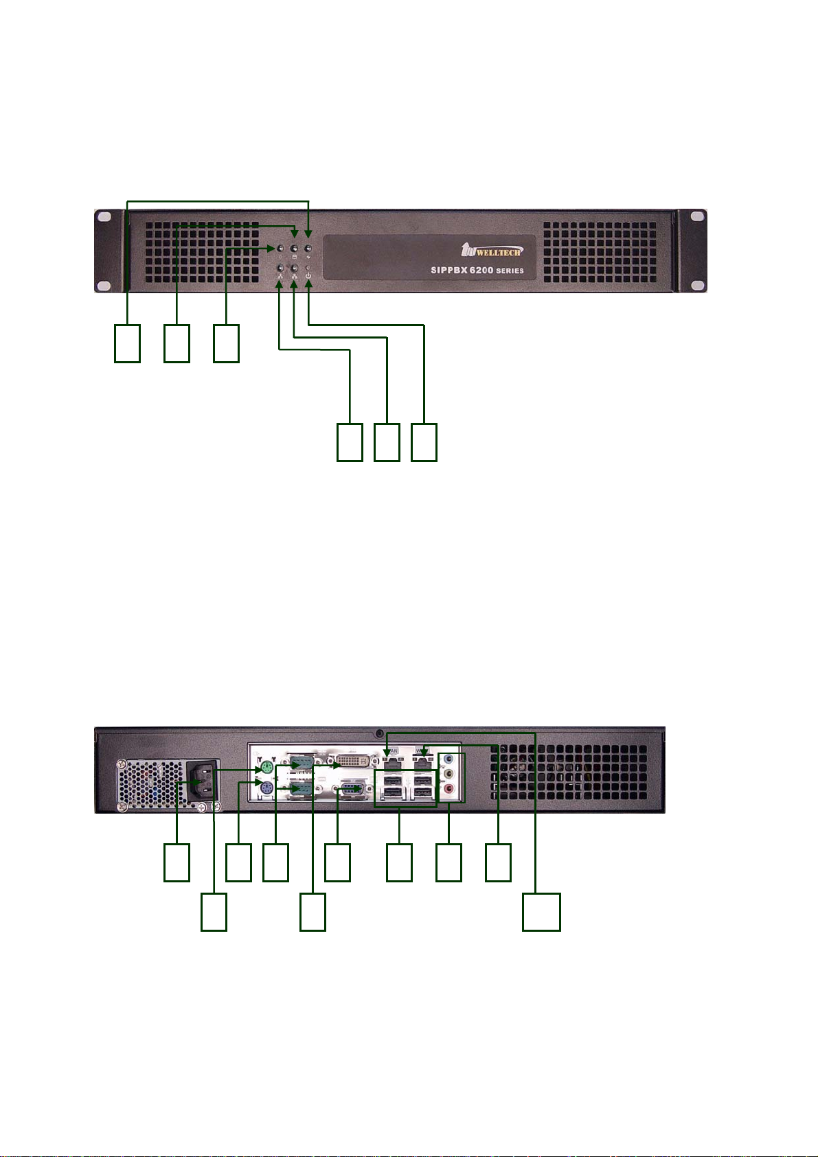
1.2.1 The Front Panel
The SIPPBX 6200A LEDs, which inform you about network activities, are located on the
front panel.
3 2 1
4 5 6
Functions:
¾ 1: System Status LED (not used)
¾ 2: H/D LED
¾ 3: Power LED
¾ 4: Network Interface LED (not used)
¾ 5: Network Interface LED (not used)
¾ 6: Power Switch
1.2.2 The Back Panel
The SIPPBX 6200A ports are located on the back panel.
2
Functions:
¾ 1: AC Power Outlet
¾ 2: Mouse (not used)
¾ 3: Keyboard
3 4
61 7 9
5
8
10
- 8 -

¾ 4: RS232 Console Port
¾ 5: DVI (not used)
¾ 6: VGA
¾ 7: USB (not used)
¾ 8: Sound (not used)
¾ 9: WAN Interface
¾ 10: LAN Interface
- 9 -

CH2. Start to configure SIPPBX 6200A
2.1 Connection SIPPBX 6200A
Step 1: Connect LAN port of SIPPBX 6200A with PC via crossover cable or connect with
Switch/ Hub via straight through cable.
Step 2: Prepare one computer, and change the IP address to be 192.168.123.12x with
subnet mask 255.255.255.0.
Step 3: Open browser and link to default LAN IP address of SIPPBX 6200A
“192.168.123.123” with default port number 10087, i.e.
http://192.168.123.123:10087
Step 4: Login SIPPBX 6200A with default user ID/Password: “root/root”. After login
SIPPBX 6200A, user can start to configure basic and essential configurations.
Step 5: To configure basic and essential configurations
To make SIPPBX 6200A work has to set some basic and essential configurations,
those include Network, Extension (FXS and IP Phone devices), and Trunk (FXO
devices).
- 10 -
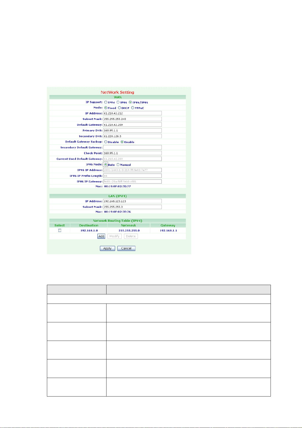
2.1.1 Network Configuration
To change your Network Setting, click Network, and then click the Network Setting
table. The screen appears as shown.
Figure Network: Network Setting
The following table describes the table in this screen
Table Network: Network Setting
Label Description
WAN
IP Support Select IP mode to provide IPv4 only, IPv6 only or dual
IPv4/IPv6.
Mode Select SIPPBX 6200A WAN port network mode to be Fixed IP,
DHCP or PPPoE.
IP Address Enter the IP Address. If user has set SIPPBX 6200A to be fixed
IP mode.
Subnet Mask Enter the Subnet Mask Address. If user has set SIPPBX 6200A
to be fixed IP mode.
Default Gateway Enter the Default Gateway Address. If user has set SIPPBX
6200A to be fixed IP mode.
- 11 -

Primary DNS Enter the IP address for Primary DNS. The default is
168.95.1.1.
Secondary DNS Enter the IP address for Secondary DNS. The default is null.
Default Gateway
Backup
Select Enable option, if there are any connection problem
occurred on primary default gateway connections, all the traffic
will be guided and switched to the secondary default gateway
for proper operation. The default is Disable.
Secondary Default
Gateway
Enter the Secondary Default Gateway. If you choose the
Default Gateway Backup to Enable.
Check Point Enter the Check Point IP address If you choose the Default
Gateway Backup to Enable. SIPPBX 6200A use the ping
command to PING this IP address in order to check if there are
any connection problem occurred on primary default gateway
connections.
Current used Default
This field display existing used Default Gateway IP address.
Gateway
PPPoE ID Enter the PPPoE ID. If you choose the Mode to PPPoE.
PPPoE PWD Enter the PPPoE Password If you choose the Mode to PPPoE.
IPV6 Mode Select Manual option. You can enter IP Address, Prefix Length
and Gateway address.
IPV6 IP Address Display the IPV6 IP Address. You can enter the IPV6 IP Address,
if you choose the IPV6 mode to Manual.
IPV6 Prefix Length Display the IPV6 Prefix Length. You can enter the IPV6 IP
Address, if you choose the IPV6 mode to Manual.
IPV6 IP Gateway Display the IPV6 Default Gateway Address. You can enter the
IPV6 Default Gateway Address, if you choose the IPV6 mode to
Manual.
MAC This field shows the MAC address. The Mac address cannot be
modified.
LAN (IPV4)
IP Address Enter the IP Address. The default is 192.168.123.123.
Subnet Mask Enter the Subnet Mask Address. The default is 255.255.255.0.
MAC This field shows the MAC address. The Mac address cannot be
modified.
Network Routing Table (IPV4)
Select Select this check box, then modify or delete it.
Destination This field shows the IP address.
Network This field shows the Subnet Mask address.
Gateway This field shows the Default Gateway address.
- 12 -

Add Click on the Add button, then display Network Router screen.
Modify IP address can be modified by clicking on the checkbox next to
the IP address and click on the Modify button.
Delete IP address can be deleted by clicking on the checkbox next to
the IP address and click on the Delete button.
Apply Click on the Apply button to save your customized settings and
exit this screen.
Cancel Click on the Cancel button to begin configuration this screen.
- 13 -
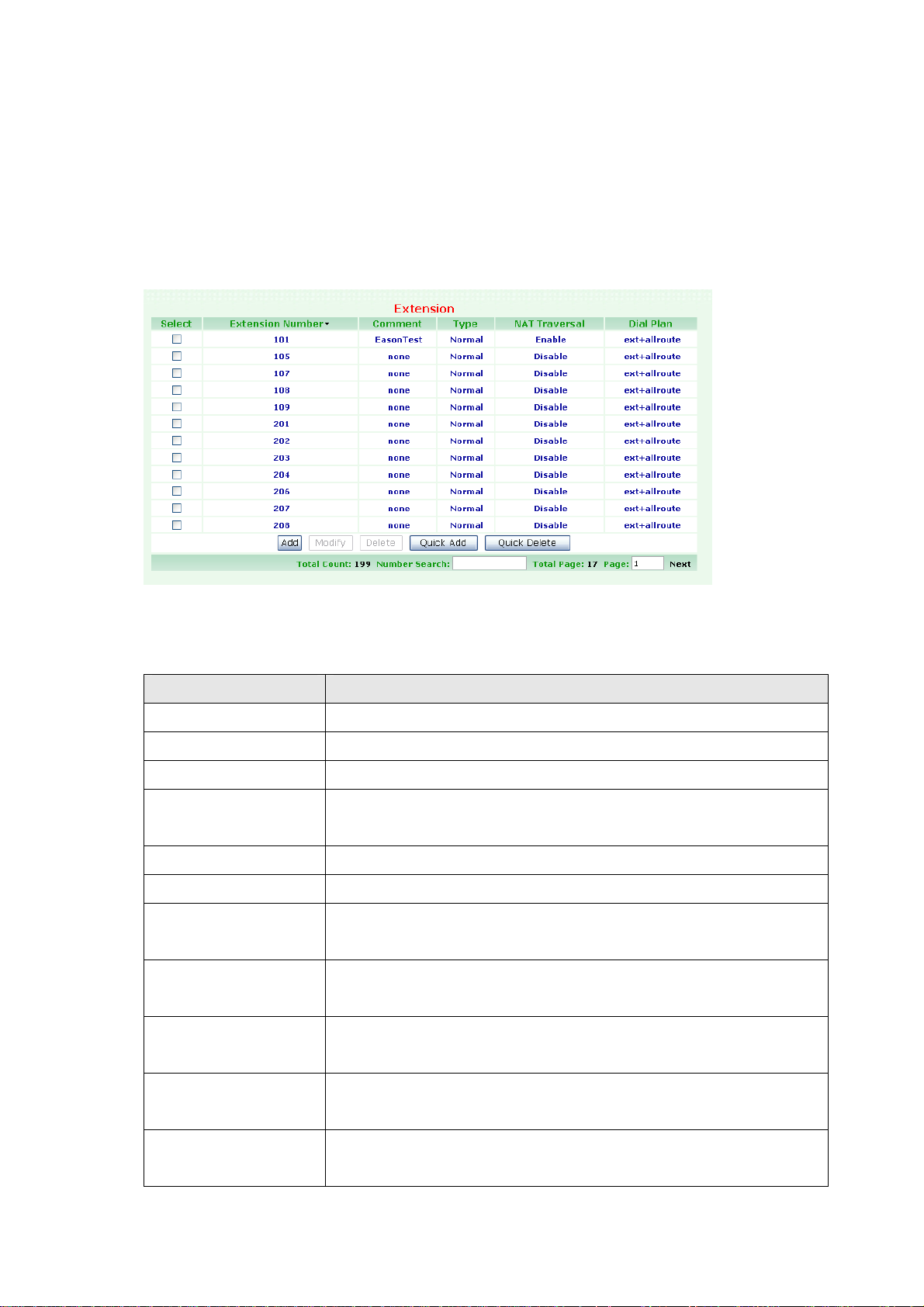
2.1.2 Extension Configuration
User has to set Extension account for extension devices to register on SIPPBX 6200A.
To change your Extension, click Configuration, and then click the Extension table. The
screen appears as shown.
Figure Configuration: Extension
The following table describes the table in this screen
Table Configuration: Extension
Label Description
Select Select this check box, then modify or delete it.
Extension Number This field shows the Extension Number.
Comment This field shows the Comment information such as user name.
Type This field shows subscriber Type information such as Auto
Configure.
NAT Traversal This field shows the NAT Traversal enable or disable.
Dial Plan This field shows the Dial Plan information includes routes plans.
Add Click on the Add button, then display a new Extension Setting
screen.
Modify An extension can be modified by clicking on the checkbox next
to the extension and click on the Modify button.
Delete An extension can be deleted by clicking on the checkbox next to
the extension and click on the Delete button.
Quick Add Click on the Add button, then display an new Extension Setting
screen.
Quick Delete Click on the Quick Delete button, then display a batch of
Extension number to be deleted.
- 14 -
Total Count This field shows Total subscriber Counts information.
Number Search Enter the search number, then click enter key. The screen will
display match search data.
Total Page This field shows Total Pages of subscriber information.
Page This field shows Page Number information where you are. You
can Enter page number, then click enter key. The screen will
display this page data.
Next/Prev Click on the Next/Prev to Next/Previous Page. The system will
auto display the Next or Previous page Information.
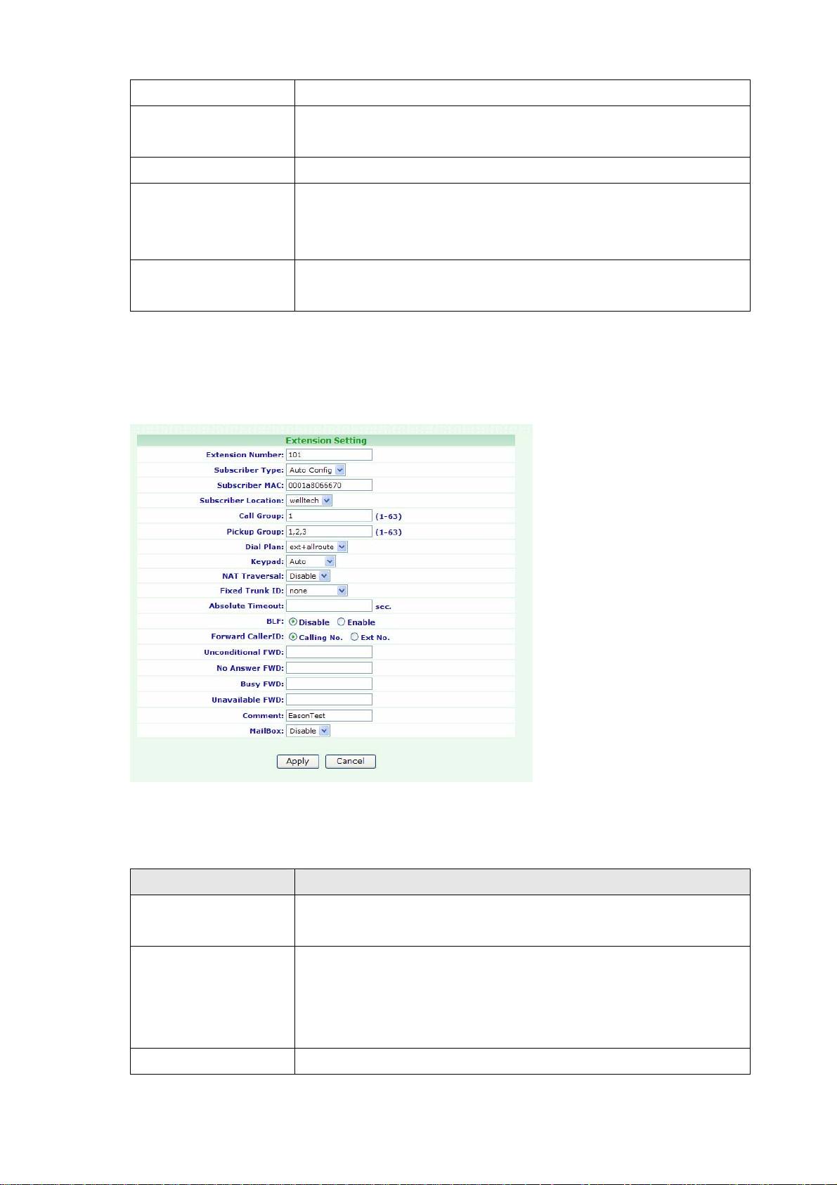
Click Add/Modify. The screen appears as shown.
Figure Configuration: Extension Setting
The following table describes the table in this screen
Table Configuration: Extension Setting
Label Description
Extension Number Assign the number of Extension. This number is also the
register name for device.
Subscriber Type Choose one option to Subscriber Type. Provide drop-down
options: Normal or Autoconfig.
Normal: You must enter Password to this subscriber.
Autoconfig: You must enter MAC Address of this subscriber.
Password Select Normal option to Subscriber Type. Assign the register
- 15 -

password for device to register on SIPPBX 6200A.
Subscriber MAC Select Autoconfig option to Subscriber Type. You must enter
the CPE Device MAC Address such as LP600N IP Phone MAC
address.
Call Group You can use the Call Group parameter to assign an Extension to
one or more groups.
Pickup Group You can use the Pickup Group option in conjunction with this
parameter to allow a ringing phone to be answered from
another extension.
Note:
The Pickup Group option is used to control which Call Groups a
channel may pick up—a channel is given authority to answer
another ringing channel if it is assigned to the same Pickup
Group as the ringing channel’s Call Group. By default, remote
ringing extensions can be answered with *8.
You can define multiple Call Groups and Pickup Groups for one
Extension by a “comma”. For example, you can input “1,3,5”
into Call Group or Pickup Group.
Dial Plan Define the dialing plan for Extension. It specifies the location of
the instruction used to control what extension is allowed to do,
and what to do with incoming calls for this extension. In this
field, you can Choose 5 dial levels for Extension, including
[ext-only], [ext+R1], [ext+R12], [ext+R123], [ext+allroutes].
You can define an “Outgoing call” record, to a certain Route
Level, as R1, R2…, etc. [ext-only] means this subscriber can
only call to Extension. [ext+R1] means the subscriber with
such Dial Plan can call to Extension and Route Level with R1.
[ext+R12] means the subscriber with such Dial Plan can call to
Extension and Route Level with R1 and R2. [ext+R123] means
the subscriber with such DialPlan can call to Extension and
Route Level with R1, R2 and R3. [ext+allroutes] means the
subscriber with such Dial Plan can call to Extension and Route
Level with R1, R2, R3 and R4(allroutes).
Note:
For more information about Route Level, please refer to the
user manual:
CH3.1.8 Outgoing Routing.
Keypad User can select Keypad type to be RFC2833, In-band, SIP-Info
and Auto. You can choose Auto to auto select the Keypad type.
Choose RFC2833, Inband or SIP-Info here will force the
Extension use RFC2833, Inband or SIP-Info accordingly and
- 16 -

the setting should be also matched the Keypad setting of
Extension device.
Note:
Now SIPPBX 6200A could not support G729 with Inband
Keypad type. If SIPPBX 6200A detect the calling party or
receiving party do not support RFC2833 DTMF type, SIPPBX
6200A will switch the voice Codec to G.711 to make sure the
DTMF detection is correctly.
NAT Traversal If the Extension device is installed behind a device performing
NAT such as firewall or router, and need to register to SIPPBX
6200A on public network, this extension has to enable this
function. Enable NAT Traversal to force SIPPBX 6200A to ignore
the contact information for the Extension and use the address
from which the packets are been received.
Fixed Trunk ID User can define a Fixed Trunk for a certain extensions. When
such extension makes an outgoing call via routing table,
SIPPBX 6200A will check “Fixed Outgoing Call Rule” first. If
“Fixed Outgoing Call Rule” is enabled, SIPPBX 6200A will
confirm the Fix Trunk ID for the calling party. That means the
outbound call will be routed by Fixed Trunk ID, if you define the
Fixed Trunk ID for the calling party and you also enable “Fixed
Outgoing Call Rule”.
Note:
For more information about Fixed Outgoing Call Rule, please
refer to the user manual:
CH3.1.8 Outgoing Routing.
Absolute Timeout Specific the timeout value for the outgoing calls. Please also go
to Outgoing Call Rule page to enable the Route Timeout
function to restrict talking time ( Toll Restriction ).
BLF Enable Busy Line Field function for extensions.
Forward CallerID By default, the “from header of SIP invite” will contain the
caller’s line number when forward function is activated. But this
may make some errors occurred for some SIP Trunk services.
So we add this function in the “Extension Setting” page, to let
user modify the line number of SIP Invite’ s from header, from
calling party’s number to the called party’s number.
Unconditional FWD Enable Unconditional forward function by adding forwarding
number.
No Answer FWD Enable No Answer forward function by adding forwarding
number.
- 17 -

Busy FWD Enable Busy forward function by adding forwarding number.
Unavailable FWD Enable Unavailable forward function by adding forwarding
number.
Comment You can input a 20 bytes note for each extension here.
Mail Box User can select to disable or enable voice mail box function. If
this function is enabled, user could input e-mail address for the
Extension. When having voice mail of incoming call left, system
will send this voice mail to the specified e-mail address. You can
also login the mail box system by dialing to *98.
E-Mail Address This field will appear when you enable Mail Box function and
you can input the E-Mail Address here for voice mail to E-mail.
Note:
Please remember to set the SMTP in the page of Management
Web, and then click SMTP Setting to activate the Voice Mail to
E-mail.
If the SIPPBX 6200A got a new message left at one subscriber,
it sends the message to the user by email immediately. If you
are using SIPPBX 6200A and you want the SIPPBX 6200A to
save voice mail to it and not send to email. You just need to
input “x” to E-Mail Address.
Save VM to Local If you select Enable to Save VM To Local when you have Voice
Mail message, this message will be saved at Local fresh
memory folder.
VM Login Password SIPPBX 6200A has a built-in voice mail system. And user can
login voice mail system by dialing to *98, then input the
mailbox number and password to retrieve voice mail. User can
define the Voice Mail box login password here. Another way to
login the voice mail system is to dial *98+extension number.
For example, dial *98101 can login extension 101 voice mail
box, and caller can enter password to access voice mail.
Voice Mail Count Display the exact count of New Messages and Old Messages.
Delete MailBox
Content
User can delete all of the voice mails and personal greeting by
marking the “Delete MailBox Content” and then press Apply.
Apply Click on the Apply button to save your customized settings and
exit this screen.
Cancel Click on the Cancel button to begin configuration of this screen.
- 18 -
2.1.3 Trunk Configuration
User has to set Trunk account for Trunk (FXO device, for instance, WellGate 2540 or 2680 )
to register to SIPPBX 6200A or set some necessary configuration for SIP trunk.
To change your Trunk, click Configuration, and then click the Trunk table. The screen
appears as follows.
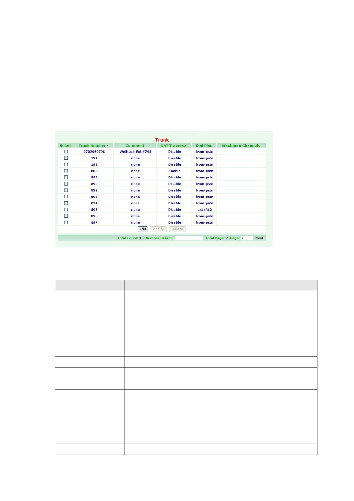
Figure Configuration: Trunk
The following table describes the table in this screen
Table Configuration: Trunk
Label Description
Select Select this check box and modify or delete it.
Trunk Number This field shows the Trunk Number information.
Comment This field shows the remark information.
NAT Traversal This field shows the NAT Traversal information.
Maximum Channels This field shows the Maximum concurrent call to this trunk.
There is no limitation if this field left blank.
Add Click on the Add button to display a new Trunk Setting screen.
Modify A Trunk can be modified by clicking on the checkbox next to the
Trunk and click on the Modify button to modify its contents.
Delete A Trunk record can be deleted by clicking on the checkbox next
to that Trunk and click on the Delete button.
Total Count This field shows Total Counts of trunk information.
Number Search Enter the search number, then click enter key. The screen will
display matched search data.
Total Page This field shows Total Pages of trunk information.
- 19 -
Page This field shows Page Number information. You can Enter page
number, then click enter key. The screen will display this page
data.
Next/Prev Click on the Next/Prev to Next/Previous Page. The system will
auto display the Next or Previous trunk Information.
Example 1: Set Trunk for FXO gateway
Click Add/Modify. The screen appears as follows.
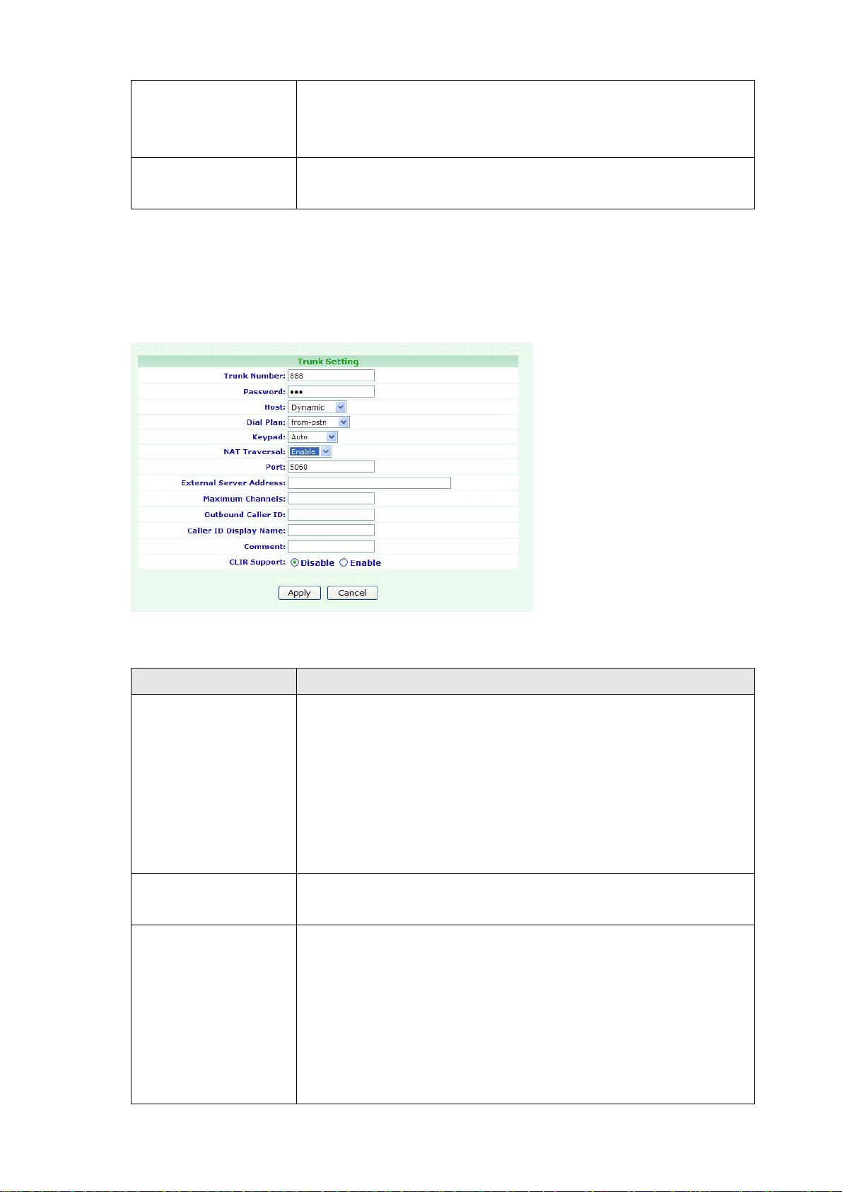
Figure Configuration: Trunk Setting
The following table describes the table in this screen
Table Configuration: Trunk Setting
Label Description
Trunk Number Assign the number of Trunk. This number is also the register
name for Trunk device.
Note: The Trunk Number can also be a “Trunk ID”. In the
Routing Table page, you should define the destination of prefix
route. When you define the prefix route, you should set the
Trunk ID (Trunk Number) in the Trunk page first; then you
could input the correct Trunk ID in the Destination field.
Password Assign the register password for device to register on SIPPBX
6200A.
Host Setting the Host to Dynamic will require the trunk to register
the SIPPBX 6200A so that the SIPPBX 6200A know how to
reach the trunk. You can also set the Host to an IP address or
FQDN (domain name) if you set the Host to [Pre-define]. There
will be a field called [Address] appeared when you choose Host
to [Pre-define]. This limits only where you place calls to, as the
user is allowed to place calls from anywhere.
- 20 -

Dial Plan Define the dialing plan for Trunk. It specifies the location of the
instruction used to control what the phone is allowed to do, and
what to do with incoming calls for this Trunk. In this field, you
can Choose 6 dial levels for Extension, including [from-pstn],
[ext-only], [ext+R1], [ext+R12], [ext+R123], [ext+allroutes].
You can define an “Outgoing call” record to a certain route
level, such as R1, R2…, etc. [from-pstn] is used for Trunk only.
[ext-only] means this subscriber can only call to Extension.
[ext+R1] means the subscriber with such Dial Plan can call to
Extension and Route Level with R1. [ext+R12] means the
subscriber with such Dial Plan can call to Extension and Route
Level with R1 and R2. [ext+R123] means the subscriber with
such Dial Plan can call to Extension and Route Level with R1, R2
and R3. [ext+allroutes] means the subscriber with such Dial
Plan can call to Extension and Route Level with R1, R2, R3 and
R4 (allroutes).
Note: For more information about Route Level, please refer to
the user manual: CH3.1.8 Outgoing Routing.
Keypad User can select Keypad type to be RFC2833, In-band, or
SIP-Info and Auto. You can choose Auto to auto select the
Keypad type. Choose RFC2833, Inband or SIP-Info here will
force the Extension to use RFC2833, Inband or SIP-Info
accordingly and the setting should be also matched the Keypad
setting of Trunk device.
NAT Traversal If the Trunk device is behind a device performing NAT, such as
firewall or router, and need to register to SIPPBX 6200A on
public network, then user has to enable this function. Enable
NAT Traversal to force SIPPBX 6200A to ignore the contact
information for the Trunk and use the address from which the
packets are been received.
Port You can use this to define the SIP signal port if you want to
listen on a nonstandard SIP signal port.
External Server
Address
This field will allow you to set the domain in the SIP From URI.
Setting this will avoid some unexpected issue if the service
provider needs this for authentication.
Maximum Channels This will limit the maximum channels for this Trunk. For
example, you set 2 into this field; only 2 outgoing calls could go
via this Trunk. Default is no limit.
Outbound Caller ID Some service provider will require the correct registered caller
ID if it got an incoming call. SIPPBX 6200A will send the
- 21 -

Extension’s caller ID to this Trunk as default value, if you set
empty here.
Note:
z Normally, SIP From URI contains the Extension’s calling ID
and SIPPBX 6200A’s IP address, but some ITSP may reject
this call due to some security issue. You can modify the
Calling ID and IP/ Domain in the fields of [External Server
Address] and [Outbound Caller ID] when the call is going
via the SIPPBX 6200A to the Destination (Trunk) to avoid
such security issue.
z If you set a Welltech FXO gateway as the Trunk, you can
use the default Trunk 888 and 889 as the FXO’s register
number.
z For the FXO gateway, you may just configure Trunk
Number, Password, Host, Dial Plan, Keypad, NAT Traversal
and RTP Mode.
z If you set the ITSP as the Trunk, you may need to set the
following configure: Port, External Server Address and
Outbound Caller ID.
Caller ID Display
Name
Comment You can input a 10 bytes note for each Trunk here.
CLIR Support CLIR means "Caller Line Identification Restriction". It is a
Apply Click on the Apply button to save your customized settings and
Cancel Click on the Cancel button to begin a new configuration on this
When inbound call is coming from Trunk, such as 888. The
caller ID Name will be the “PSTN number” or “888”. Specify this
will use the current setting instead.
proper noun. It is a feature to hide the caller's number. For
example, ext 101 call to ext 102. But 101 won’t like to show the
caller ID to 102. So 101 can activate this feature to hide the
caller ID. When 102 got a call from 101, the LCD of 102 should
display "Anonymous".
exit this screen.
screen.
- 22 -
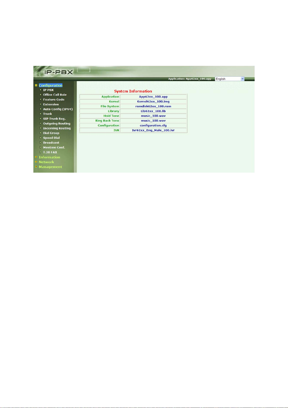
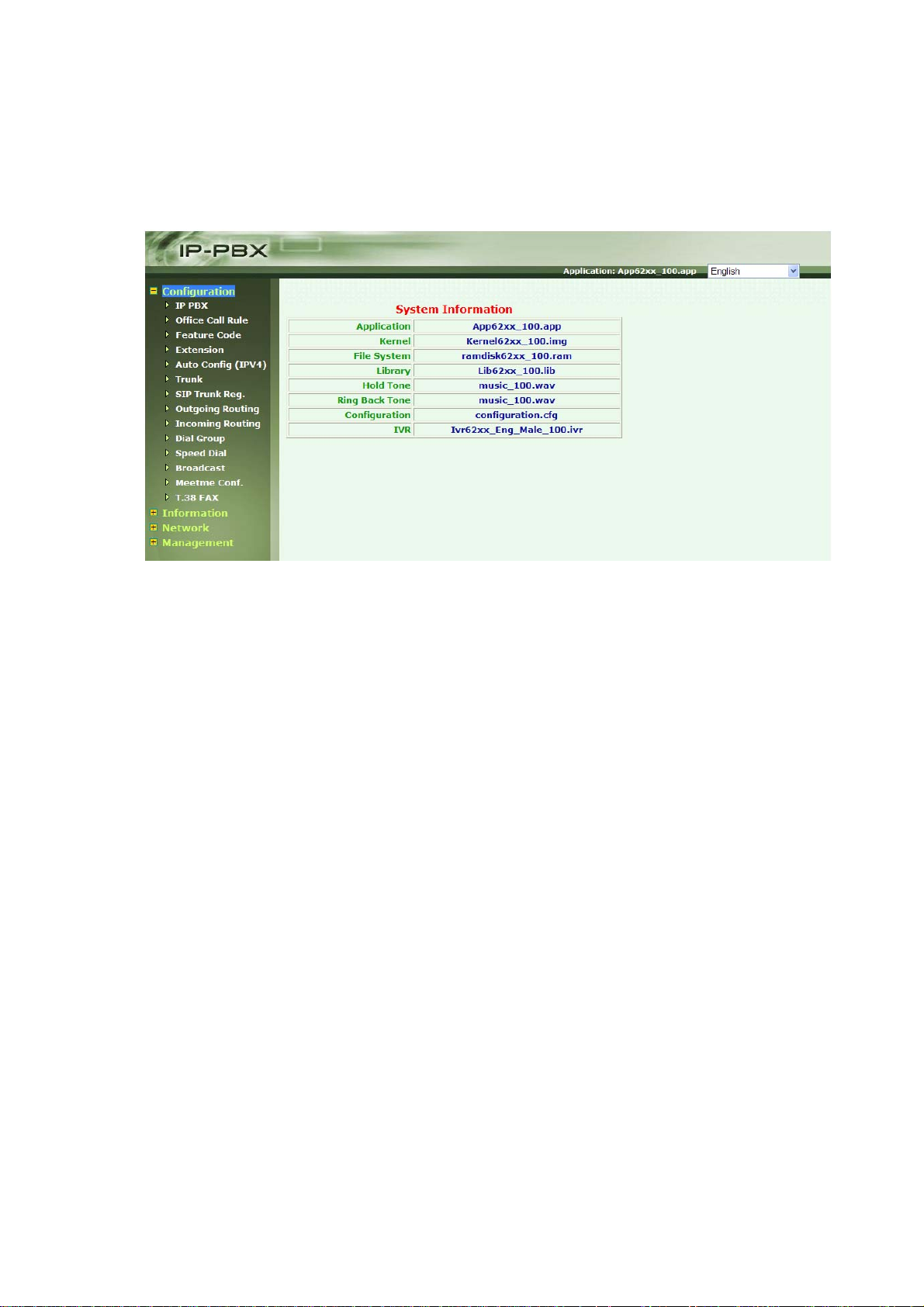
CH3. Full Web Configurations
After Login SIPPBX 6200A, you will see screen as below, and there are four main
categories, user can click on each category to extend detail items.
Configuration: Include all telephony configurations of SIPPBX 6200A.
• IP PBX
• Office Call Rule
• Feature Code
• Extension
• Auto Config (IPv4)
• Trunk
• SIP Trunk Reg.
• Outgoing Routing
• Incoming Routing
• Dial Group
• Speed Dial
• Broadcast
• Meetme Conf.
• T.38 FAX
Information: To show related information.
• Subscriber Info.
• Call Monitor
• CDR
• System Info.
Network: To show related information.
• Network
- 23 -

• DHCP Server. (IPv4)
• DDNS Server. (IPv4)
Management: Include all system management of SIPPBX 6200A.
• Time Setting
• SMTP Setting
• VM Setting
• Security
• Firmware Upload
• Music Upload
• Import Setting
• Export Setting
• Reset To Default
• Reboot System: To reboot system of SIPPBX 6200A.
• Power Off System
- 24 -
3.1 Configuration
The Network screens can help you configure IP PBX, Office Call Rule, Feature Code,
Extension, Auto configure (IPV4), Trunk, SIP Trunk Reg., Outgoing Routing, Dial Group,
Speed Dial, Broadcast, Meetme Conf., T.38 FAX.
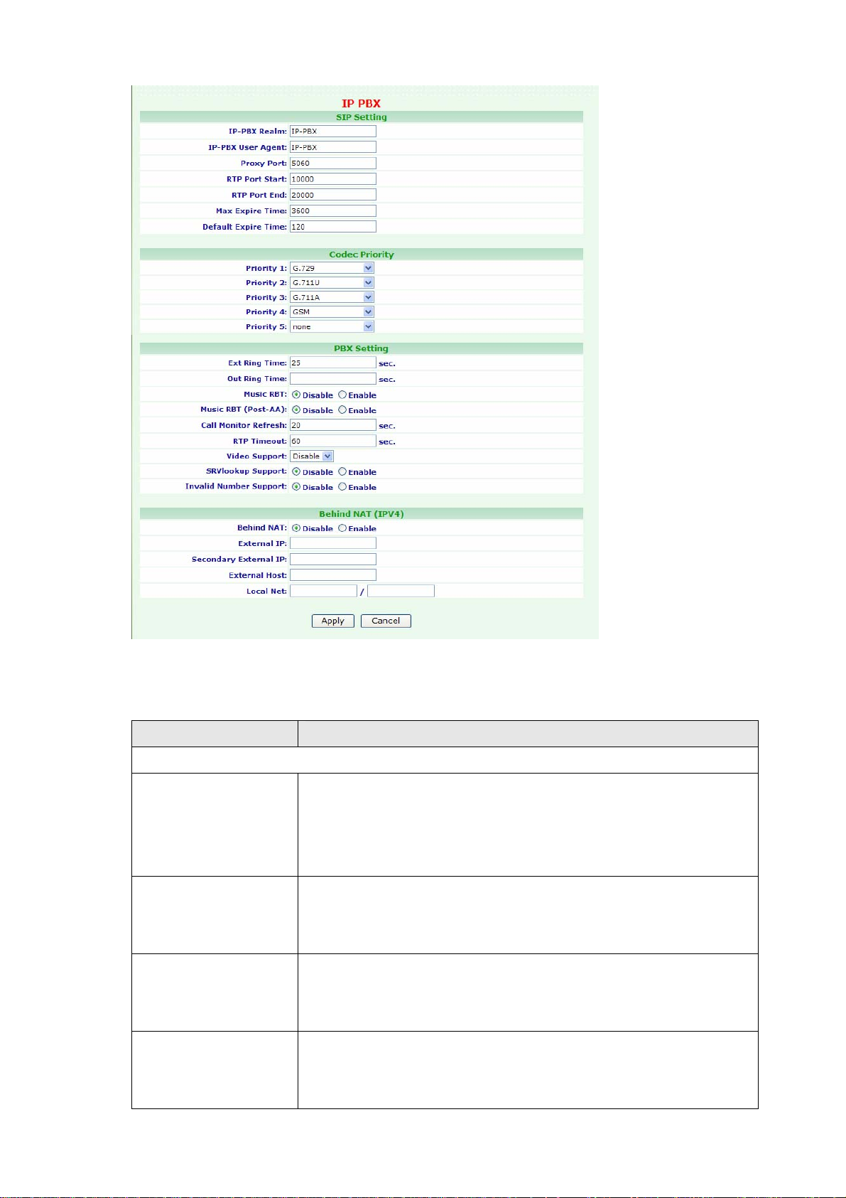
3.1.1 IP PBX
To change your IP PBX Setting, click Configuration, and then click the IP PBX table. The
screen appears as follows.
Figure Configuration: IP PBX
- 25 -
The following table describes the table in this screen
Table Configuration: IP PBX
Label Description
SIP Setting
IP-PBX Realm Enter the IP-PBX Realm of SIPPBX 6200A. This parameter is
essential when there is more than one SIPPBX 6200A, and user
wants to have inter-calls between SIPPBX 6200A. Please refer to
SIP Trunk configuration.
IP-PBX User Agent Enter the IP-PBX User Agent. IP-PBX User Agent takes as its
argument a string specifying the value for the user agent field
in the SIP header. The default value is IP-PBX.
Proxy Port Enter the Proxy Port. These optional parameters allow you to
control the port on which you wish the SIPPBX 6200A to accept
SIP connections. Default is 5060.
RTP Port Start Enter the RTP Port Start. The voice media will use RTP as the
transport protocol. You can define the RTP port range that
SIPPBX 6200A opened. Default start port is 10000.
- 26 -

RTP Port End Enter the RTP Port End. The voice media will use RTP as the
transport protocol. You can define the RTP port range that
SIPPBX 6200A opened. Default end port is 20000.
Note: Default RTP port range is 10000 to 20000 and default
proxy port is 5060. If your SIPPBX 6200A is behind a firewall,
please make sure you have already opened the RTP port
(10000-20000) and proxy port (5060). And you should also
make sure the proxy port (5060) has already mapped to
SIPPBX 6200A.
Max Expire Time This sets the maximum amount of time, in seconds. This is
used for the registration expiry time. If this value is less than
the expiry time from the client, and then click the SIPPBX
6200A will reply a certain expiry time which is defined in
“Default Expire Time” to client.
Default Expire Time This sets the default SIP registration expiry time, in seconds. A
client will normally define this value when it initially registers,
so the default value you set here will be used only if the client
does not specify a timeout when it registers. If you are
registering to another SIP Trunk, this is the registration timeout
that it will send to the far end.
Codec Priority
Codec Priority Codec negotiation is attempted in the order in which the voice
Codec Priority is defined. Default is G.729 with the first priority,
G.711u with second priority, G.711A with third priority and
GSM is fourth priority. That means the SIPPBX 6200A can only
recognize these four Codecs and it will force the voice Codec
with the specified priority and forward to another subscriber.
Now, SIPPBX 6200A can support G.729, G.711U, G.711A, GSM
and G.723 Pass-Thru.
PBX Setting
Ext Ring Time This field defines the timeout value if the call is made between
Extension to Extension. Default is 20 seconds.
Out Ring Time This field defines the timeout value if the call is made from
Extension to outside Line (defined by routing table). Default is
no limitation timeout.
Music RBT If this call was made between extensions. Enabling this option
will provide music to the calling party as Ring Back Tone until
the call was answered.
Music RBT (After AA) If this call was forwarded from Auto Attendant. Enabling this
- 27 -

option will provide music to the calling party as Ring Back tone
until the call was answered.
Call Monitor Refresh SIPPBX 6200A has call monitor function. The call situation will
be refreshed by the refresh times. Default is 30 seconds and
user can change it here.
RTP Timeout It terminates a call if no RTP data received within the time
specified.
Video Support This field will enable video call with H263 pass-through or
MPEG4 pass-through.
Video Format Choose one option to Video Format. Provide drop-down
options: H263 pass-through or MPEG4 pass-through.
SRVlookup Support Enable or disable SRV lookup. DNS SRV is a way of setting up a
logical, resolvable address where you can be reached. This
allows calls to be forwarded to different locations without the
need to change the logical address, but your DNS Server must
support it as well. If you are not sure, please disable it. This
option is Disable, Enable by default.
Invalid Number
Support
Normally, a busy tone will be heard if caller dial to a non-exist
number. Enable this option, the caller should hear an
announcement to notify that this number is not existed.
Behind NAT
Behind NAT If your SIPPBX 6200A is installed behind NAT, we strongly
suggest you to enable Behind NAT to avoid some unexpected
issues, such as “one way voice”.
External IP If you enter External IP address, SIPPBX 6200A will take that IP
address as its argument. If SIPPBX 6200A is behind NAT, the
SIP header will normally use the private IP address assigned to
the server. The remotely device does not know how to route
back to this address; therefore, it must be replaced with a
valid, routable address.
Secondary External
IP
This should cooperate with Default Gateway Backup in Network
page. When Default Gateway Backup is enabled, the SIPPBX
6200A will auto switch the default gateway to secondary one if
primary default gateway is broken. The External IP is not
functional when Backup Default Gateway is chosen. So you
must enter the Secondary External IP for Backup Default
Gateway.
External Host External Host takes a fully qualified domain name as its
argument. If SIPPBX 6200A was installed behind NAT, the SIP
- 28 -

header will normally use the private IP address assigned to the
server. If you set this option, SIPPBX 6200A will perform
periodically DNS lookups on the hostname and replace the
private IP address with the IP address returned from the DNS
lookup.
Note: You should not set both of External IP and External Host
together; otherwise there will be some unexpected problems
appeared. That means you can only choose either External IP
or External Host for “Behind NAT”.
Local Net Local Net is used to tell SIPPBX 6200A which IP addresses are
considered local. If one of caller or callee is not under Local Net,
SIPPBX 6200A will set the address in the SIP header that can be
translated to that specified by External IP or the IP address can
be looked up with External Host. The format will be IP/ Subnet
Mask. Example: 192.168.1.0/ 255.255.255.0
Apply Click on the Apply button to save your customized settings and
exit this screen.
Cancel Click on the Cancel button to begin configuration this screen
afresh.
- 29 -
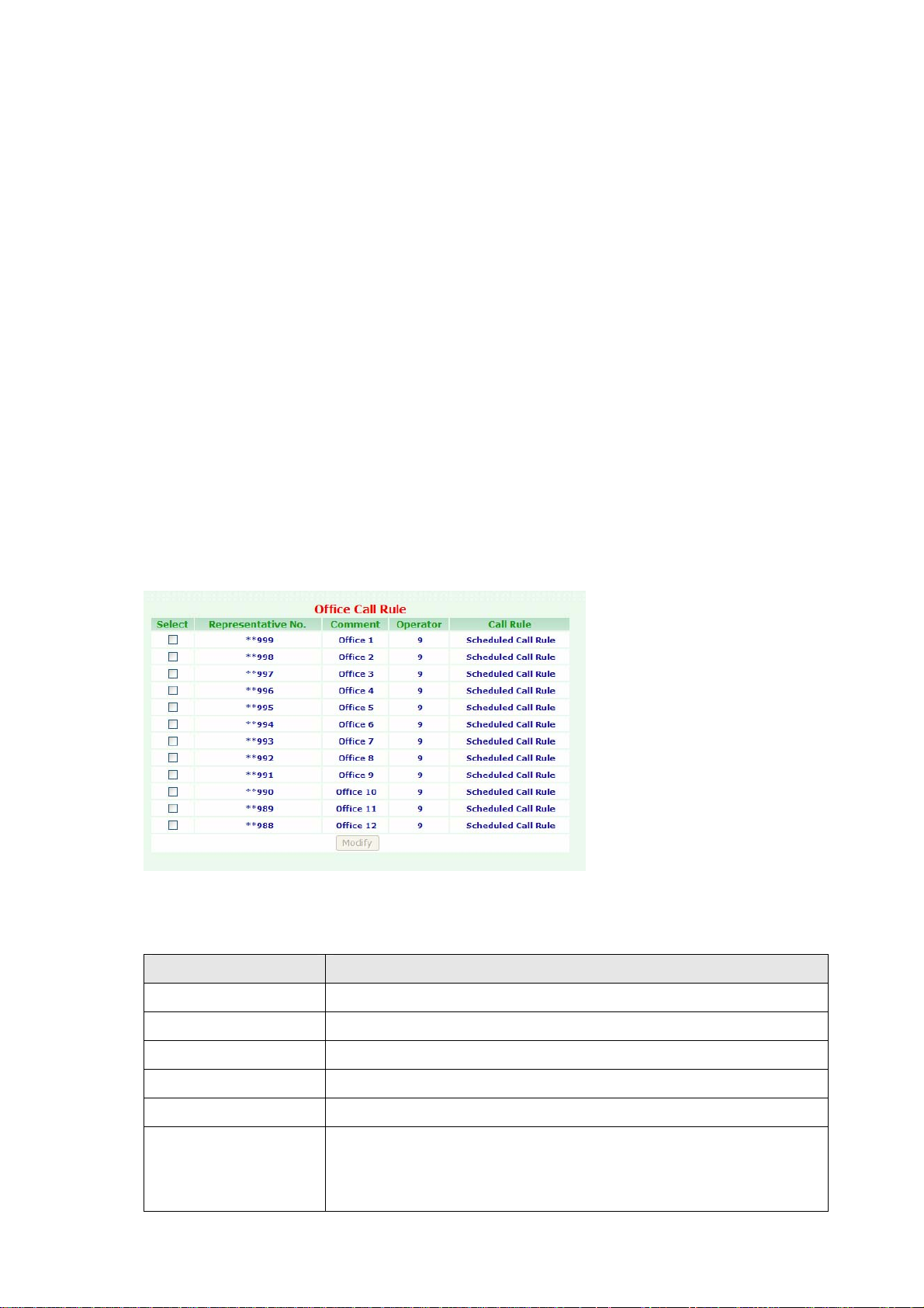
3.1.2 Office Call Rule
You can define a business time to forward incoming call to company announcement or a
certain destination.
6200A provide 12 kinds of office call rule (**998 to **988). User can setup a FXO gateway
and hotline to **999 (for office 1) or **988 (for office 12) to reach auto attendant.
Now user can make SIPPBX 6200A to decide the destination when it got an invite with
called number as **999 to **988. When SIPPBX 6200A got an invite with **999, SIPPBX
6200A will confirm the current time and forward this call to AA, Ext, Group or Outbound. If
you choose the destination to EXT, Group or Outbound, please remember to input the
destination number into the following field.
When you set the destination to AA, please refer to CH4.1.3 How to record the other
system prompts for the greeting recording.
To change your Office Call Rule, click Configuration, and then click the Office Call Rule
table. The screen appears as shown below.
Figure Configuration: Office Call Rule
The following table describes the table in this screen
Table Configuration: Office Call Rule
Label Description
Select Select this check box, then modify it.
Representative No. This field shows the Representative number information
Comment This field shows the Comment information.
Operator This field shows the Operator information.
Call Rule This field shows the Call Rule information.
Modify A Representative number can be modified by clicking on the
checkbox next to the Representative number and click on the
Modify button.
- 30 -

Click Modify. The screen appears as shown below.
Figure Configuration: Office 1 Call Rule
The following table describes the table in this screen
Table Configuration: Extension Setting
Label Description
General Setting
Representative No Enter the Representative Number.
Comment You can enter a 20 bytes note to each comment information.
Call Rule
Rule Choose one option to the Call Rule. Provide drop-down options:
Scheduled Call Rule, Fixed to Working Time Call Rule, Fixed to
Non-working Time Call Rule, Fixed to Special Time Call Rule.
Working Day Choose one option to the Working Day.
Working Time AM Choose one option to the Working Time AM.
To: Chose one option to the Rule. Provide drop-down options:
AA, EXT, Group, Outbound. If you select “EXT or Group and
Outbound”, will auto display “-- ” field. You must enter the “EXT
or Group and Outbound” data in this field.
Lunch Break Choose one option to the Lunch Break time.
- 31 -

To: Choose one option to the Rule. Provide drop-down options:
AA, EXT, Group, Outbound. If you select “EXT or Group and
Outbound”, will auto display “-- ” field. You must enter the “EXT
or Group and Outbound” data in this field.
Working Time PM Choose one option to the Working Time PM.
Non-working Time Choose one option to the Non-working Time.
Operator setting
Operator Configure the Operator number and the destination to
Extension or Call Group.
OP to EXT If you set Operator to EXT, you can enter extension number
here.
OP Ext End To When you set Operator as an Extension, you can define the
final destination to IVR system or Extension’s function (i.e.
voice mail) if Operator does not answer.
AA setting
Play AA Greeting You can define the times of greeting announcement, when
caller reached Auto Attendant system.
AA Greeting End &
Interval Timer
By default, the caller will hear greeting message 3 times when
he reaches the auto attendant. There will be an 3 seconds
interval between these greeting messages. Users can change
the intervals here.
AA Greeting End To
(Working Time)
AA Greeting End To
(Lunch Break)
AA Greeting End To
(non-Working Time)
AA Greeting End To
(Special Time)
Decide the destination after greeting announcement finished
on working time.
Decide the destination after greeting announcement finished
on Lunch Break time.
Decide the destination after greeting announcement finished
on non-Working time.
Decide the destination after greeting announcement finished
on Special time.
Import Greeting File Name: Choose one option Greeting file. Provide
drop-down options: greeting-day.wav (Working Time
Greeting), greeting-noon.wav (Lunch Break Greeting).
File: Type in the location of the file you want to upload in this
field or click on the Browse button to find it.
Import: Click on the Import button to upload greeting file.
Apply Click on the Apply button to save your customized settings and
exit this screen.
Cancel Click on the Cancel button to begin configuration this screen
afresh.
- 32 -

3.1.3 Feature Code
To change your Feature Code, click Configuration, and then click the Feature Code
table. The screen appears as shown below.
Figure Configuration: Feature Code
The following table describes the table in this screen
Table Configuration: Feature Code
Label Description
System Prompt
Recording
System Prompt
Recording PWD
User could dial an access code for system prompt recording,
such as **111 for greeting-day.wav. Before dialing to **111,
user should dial to the feature code of “System Prompt
Recording” to start recording. Default feature code for System
Prompt Recording is [*50]. So the recording procedure should
be “Dial to [*50]Æ Input password (which defined in [System
Prompt Recording PWD])Æ dial to access code (i.e. **111)Æ
Start recording”. Add this feature for recording will avoid an
unknown user incautious to record the system prompt.
Before recording System Prompt, user may need to input
password. Here you can specify the password for System
- 33 -

Prompt Recording. Default is 000. That means password is not
necessary if this field is empty.
System Prompt
Recording Prefix
System Prompt
Listen Prefix
The prefix is for access code of System Prompt Recording.
Default is **. For example, the access code for
[greeting-day.wav] is **111. So the System Prompt Recording
Prefix is **. If you change the Prefix to *1, that means the
access code for [greeting-day.wav] should be *1111.
Note: Previously, you can just dial to the access code, such as
**111, for announcement recording. But we change this
procedure due to the security issue.
For example, the record procedure of greeting message will be:
“Dial to [*50]Æ Input password [000]Æ dial to access code
[**111]Æ Start to record greeting-day.wav”. For more
information about announcement recording, please refer to
user manual:
CH4.1.3 How to record the other system
prompts
The prefix is for access code of System Prompt listening.
Default is ***. For example, the access code for
[greeting-day.wav] listening is ***111. So the System Prompt
Recording Prefix is ***. If you change the Prefix to *11, that
means the access code for [greeting-day.wav] listening should
be *11111.
DND Activated The code to activate DND. Default is *78.
DND Deactivated The code to deactivate DND. Default is *79.
UCF Activated The code to activate Unconditional Forward. Default is *72. For
example, dialing to *72101 will forward all the call to 101.
UCF Deactivated The code to deactivate Unconditional Forward. Default is *73.
BF Activated The code to activate Busy Forward. Default is *90. For
example, dialing to *90101 will forward call to 101 if you are on
the phone.
BF Deactivated The code to deactivate Busy Forward. Default is *91.
NAF Activated The code to activate No Answer Forward. Default is *92. For
example, dialing to *92101 will forward call to 101 if you are
not answering.
NAF Deactivated The code to deactivate No Answer Forward. Default is *93.
UAF Activated The code to activate Unavailable Forward. Default is *94. For
example, dialing to *94101 will forward call to 101 if your
phone is not registering.
UAF Deactivated The code to deactivate Unavailable Forward. Default is *95.
- 34 -

OUCF Start Provide user to use remote control function, then control
Unconditional Forward. Default is *87.
Note:
1. You can just dial to the PBX, and then PBX will play greeting
message.
2. Dial to [*87] to use remote control function; then play
greeting message.
3. You can enable or disable OUCF function.
OUCF Activated The code to activate Unconditional Forward. Default is *88.
Note:
1. You can just dial to the PBX, and then PBX will play greeting
message.
2. Dial to [*87] to use remote control function; then play
greeting message.
3. After, dialing to *880282265699 will forward all the call to
0282265699.
OUCF Deactivated The code to set disable for Unconditional Forward. Default is
*89.
Note:
1. You can just dial to the PBX, and then PBX will play greeting
message.
2. Dial to [*87] to use remote control function; then play
greeting message.
3. After, dialing to [*89] to disable OUCF function.
CF Deactivated Disable all of the forward function, including Unconditional
Forward, Busy Forward, No Answer Forward and Unavailable
Forward. Default is *96.
Voice Mail Box Login For SIPPBX 6200A only. SIPPBX 6200A has the ability to store
voice mail within itself, and user can just dial to the feature
code to login the voice mail system. The feature code of voice
mail system default is *98.
Camp-On Activated This function means [call back on busy]. For example, you dial
to 101 but 101 is on the phone, then you should hear an
announcement for called person is busy. You could dial to *66
by default to trigger the SIPPBX 6200A call back to you when
101 is idle. This function will let you talk to called party
immediately when called party is free.
Note:
This Function is only workable when voice mail function is
disabled.
- 35 -

When this function is enabled, SIPPBX 6200A will check the
status of called party every 20 seconds, at most 15 times. That
means the camp-on function may be performed when called
party is idled after 20 seconds at most. And 300 (20*15)
seconds later, this function will not be workable.
CLIR (per call) Prefix Default is *67. Add this prefix will hide the caller’s number. For
example, 101 does not want to show the caller id to 102. The
101 can dial to "*67102", where the *67 is the prefix for CLIR.
When 102 got the incoming call, the LCD of 102 should display
"Anonymous". If 101 dials to "102", 102 should see the Caller
ID as 101.
CLIR Activated Default is *31. For example, 101 dial to "*31", SIPPBX 6200A
should add the CLIR record for 101 into its database. When 101
call to 102, 103...,etc. The LCD of called party should always
show "Anonymous".
CLIR Deactivated Default is *32. Dialing to *32 will remove the CLIR record from
the database of SIPPBX 6200A.
Ext Pwd Activated Ext Pwd means extension password. This is a personal
password for external outgoing call. For example, ext 101 dial
to *80+123, The Ext Pwd is activated. From now on, the ext
101 must enter the password 123 prior to make external
outgoing calls which are defined in the [Outgoing Routing]
page..
Ext Pwd Deactivated This is a feature code to disable extension password (Ext Pwd).
Apply Click on the Apply button to save your customized settings and
exit this screen.
Cancel Click on the Cancel button to begin configuration this screen
afresh.
- 36 -

3.1.4 Extension
User has to set Extension account for other device to register on SIPPBX 6200A.
To change your Extension, click Configuration, and then click the Extension table. The
screen appears as shown below.
Figure Configuration: Extension
The following table describes the table in this screen
Table Configuration: Extension
Label Description
Select Select this check box, then modify or delete it.
Extension Number This field shows the Extension Number information
Comment This field shows the Comment information.
Type This field shows the Type information.
NAT Traversal This field shows the NAT Traversal information.
Dial Plan This field shows the Dial Plan information.
Add Click on the Add button, then display Extension Setting screen.
Modify An extension can be modified by clicking on the checkbox next
to the extension and click on the Modify button.
Delete An extension can be deleted by clicking on the checkbox next to
an extension and click on the Delete button.
Quick Add Click on the Add button, then display Extension Setting screen.
Quick Delete Click on the Add button, then display Extension Setting screen.
Total Count This field shows Total Counts information.
Number Search Enter the search number, then click enter key. The screen will
display matched search data.
Total Page This field shows Total Page information.
- 37 -

Page This field shows Page Number information. You can Enter page
number, then click enter key. The screen will display this page
data.
Next/Prev Click on the Next/Prev to Next/Previous Page. The system will
auto display the Next or Previous Information.
Click Add/Modify. The screen appears as shown below.
Figure Configuration: Extension Setting
The following table describes the table in this screen
Table Configuration: Extension Setting
Label Description
Extension Number Assign the number of Extension. This number is also the
register name for device.
Subscriber Type Choose one option to Subscriber Type. Provide drop-down
options: Normal, Autoconfig.
Normal: You must enter Password.
Autoconfig: You must enter MAC Address.
Password Select Normal option to Subscriber Type. Assign the register
password for device to register on SIPPBX 6200A.
Subscriber MAC Select Autoconfig option to Subscriber Type. You must enter
the CPE Device MAC Address.
Call Group You can use the Call Group parameter to assign an Extension to
- 38 -

one or more groups.
Pickup Group You can use the Pickup Group option in conjunction with this
parameter to allow a ringing phone to be answered from
another extension.
Note:
The Pickup Group option is used to control which Call Groups a
channel may pick up—a channel is given authority to answer
another ringing channel if it was assigned to the same Pickup
Group as the ringing channel’s Call Group. By default, remote
ringing extensions can be answered with *8.
You can define multiple Call Groups and Pickup Groups for one
Extension by a “comma”. For example, you can enter “1,3,5”
into Call Group or Pickup Group.
DialPlan Define the dialing plan for Extension. It specifies the location of
the instruction used to control what the phone is allowed to do,
and what to do with incoming calls for this extension. In this
field, you can Choose 5 dial levels for Extension, including
[ext-only], [ext+R1], [ext+R12], [ext+R123], [ext+allroutes].
You can define an “Outgoing call” record to a certain Route
Level as R1, R2…, etc. The [ext-only] means this subscriber can
only call to Extension. [ext+R1] means the subscriber with
such Dial Plan can call to Extension and Route Level with R1.
[ext+R12] means the subscriber with such Dial Plan can call to
Extension and Route Level with R1 and R2. [ext+R123] means
the subscriber with such Dial Plan can call to Extension and
Route Level with R1, R2 and R3. [ext+allroutes] means the
subscriber with such Dial Plan can call to Extension and Route
Level with R1, R2, R3 and R4.
Note:
For more information about Route Level, please refer to the
user manual:
CH3.1.8 Outgoing Routing.
Keypad User can select Keypad type to be RFC2833, In-band, SIP-Info
and Auto. You can choose Auto to auto select the Keypad type.
Choose RFC2833, Inband or SIP-Info here will force the
Extension use RFC2833, Inband or SIP-Info only and the
setting should be also matched the Keypad setting of Extension
device.
Note:
Now SIPPBX 6200A does not support G.729 with Inband
Keypad type. If SIPPBX 6200A detect the caller or callee not
- 39 -

support RFC2833 DTMF type. Then SIPPBX 6200A will transfer
the voice Codec to G.711 to make sure the DTMF detection is
working correctly.
NAT Traversal If the Extension device is behind a device performing NAT, such
as firewall or router, and need to register to SIPPBX 6200A on
public network, then user has to enable this function. Enable
NAT Traversal to force SIPPBX 6200A to ignore the contact
information for the Extension and use the address from which
the packets are been received.
Fixed Trunk ID User can define a Fixed Trunk for a certain extension. When
such extension makes an outgoing call via routing table,
SIPPBX 6200A will check “Fixed Outgoing Call Rule” first. If
“Fixed Outgoing Call Rule” is enabled, SIPPBX 6200A will
confirm the Fix Trunk ID for the calling party. That means the
outbound call will be routed by Fixed Trunk ID, if you define the
Fixed Trunk ID for the calling party and you also enable “Fixed
Outgoing Call Rule”.
Note:
For more information about Fixed Outgoing Call Rule, please
refer to the user manual:
CH3.1.8 Outgoing Routing.
Absolute Timeout Specific the timeout value for the outgoing calls. Please also go
to Outgoing Call Rule page to enable the Route Timeout
function.
BLF Enable BLF ( Busy line Field ) function for extensions.
Forward CallerID By default, the “from header of SIP invite” will contain the
caller’s line number when forward function is activated. But this
may make some errors occurred for some SIP Trunk services.
So we add this function in the “Extension Setting” page, let
user modify the line number of SIP Invite’ s from header, from
calling party’s number to the called party’s number.
Unconditional FWD Enable Unconditional forward function for extensions.
No Answer FWD Enable No Answer forward function for extensions.
Busy FWD Enable Busy forward function for extensions.
Unavailable FWD Enable Unavailable forward function for extensions.
Comment You can enter a 20 bytes note for each extension here.
Mail Box User can disable or enable mail box function. If this function is
enabled, user could enter e-mail address for the Extension.
When having voice mail of incoming call left, system will send
this voice mail to the specified e-mail address. You can also
- 40 -

login the mail box system by dialing *98.
E-Mail Address This field will appear when you enable Mail Box function and
you can enter the E-Mail Address here for voice mail to E-mail.
Note:
Please remember set the SMTP in the page of Management,
and then click SMTP Setting to activate the Voice Mail to E-mail.
If the SIPPBX 6200A got a new message, it will send the
message to the user by email immediately. If you are using
SIPPBX 6200A and you want the SIPPBX 6200A to save voice
mail to it and not send the email. You simply need to enter “x”
to E-Mail Address.
Save VM to Local If you select Enable to Save VM To Local instead when you have
Voice Mail message. It will back up this voice mail to Local
folder.
VM Login Password SIPPBX 6200A has a built-in voice mail system. And user can
login voice mail system by dialing *98, then enter the mailbox
number and password for voice mail. User can define the Voice
Mail box login password here. Another way to login the voice
mail system is to dial *98+extension number. For example, dial
*98101 can login EXT101’s voice mail box, and caller can just
enter password to access voice mail.
Voice Mail Count Display the exact count of New Messages and Old Messages.
Delete MailBox
Content
User can delete all of the voice mails and personal greeting by
marking the “Delete MailBox Content” and then press Apply.
Apply Click on the Apply button to save your customized settings and
exit this screen.
Cancel Click on the Cancel button to begin configuration this screen
afresh.
Click Quick Add. The screen appears as shown below.
Figure Configuration: Extension Setting
- 41 -

The following table describes the table in this screen
Table Configuration: Extension Setting
Label Description
Quick Add Enter the number of the Quick Add. If you enter 30, an new
extension number will be created by adding one number from
starting extension number within 30 new numbers. For
instance, the starting extension number is 330, the new
created numbers are from 330 to 359.
Extension Number Assign the starting number of Extension. This number is also
the register name for device.
Subscriber Type Choose one option to Subscriber Type. Provide drop-down
options: Normal, Autoconfig.
Normal: You must enter Password.
Password Select Normal option to Subscriber Type. Assign the register
password for device to register on SIPPBX 6200A, the password
will automatically increase by 1 digit.
Call Group You can use the Call Group parameter to assign an Extension to
one or more groups.
Pickup Group You can use the Pickup Group option in conjunction with this
parameter to allow a ringing phone to be answered from
another extension.
Note:
The Pickup Group option is used to control which Call Groups a
channel may pick up—a channel is given authority to answer
another ringing channel if it was assigned to the same Pickup
Group as the ringing channel’s Call Group. By default, remote
ringing extensions can be answered with *8.
You can define multiple Call Groups and Pickup Groups for one
Extension by a “comma”. For example, you can input “1,3,5”
- 42 -

into Call Group or Pickup Group.
DialPlan Define the dialing plan for Extension. It specifies the location of
the instruction used to control what the phone is allowed to do,
and what to do with incoming calls for this extension. In this
field, you can Choose 5 dial level for Extension, including
[ext-only], [ext+R1], [ext+R12], [ext+R123], [ext+allroutes].
You can define an “Outgoing call” record, to a certain Route
Level, as R1, R2…, etc. [ext-only] means this subscriber can
only call to Extension. [ext+R1] means the subscriber with
such DialPlan can call to Extension and Route Level with R1.
[ext+R12] means the subscriber with such DialPlan can call to
Extension and Route Level with R1 and R2. [ext+R123] means
the subscriber with such DialPlan can call to Extension and
Route Level with R1, R2 and R3. [ext+allroutes] means the
subscriber with such DialPlan can call to Extension and Route
Level with R1, R2, R3 and R4.
Note:
For more information about Route Level, please refer to the
user manual:
CH3.1.8 Outgoing Routing.
NAT Traversal If the Extension device is behind a device performing NAT, such
as firewall or router, and need to register to SIPPBX 6200A on
public network, then user has to enable this function. Enable
NAT Traversal to force SIPPBX 6200A to ignore the contact
information for the Extension and use the address from which
the packets are being received.
BLF Enable BLF function for extensions.
Mail Box User can select to disable or enable mail box function. If this
function is enabled, user could input e-mail address for the
Extension. When having voice mail of incoming call, system will
send this voice mail to the specified e-mail address. You can
also login the mail box system by dialing to *98, if you are
using an SIPPBX 6200A.
Save VM to Local If you select Enable to Save VM To Local, when you have Voice
Mail message, will backup to Local folder.
VM Login Password SIPPBX 6200A has a built-in voice mail system. And user can
login voice mail system by dialing to *98, then input the
mailbox number and password for voice mail. The password
will automatically increase by 1 digit. User can define the Voice
Mail box login password here. Another way to login the voice
mail s y s tem is dia l to *98+ex t e nsion number. For example, dial
- 43 -

to *98101 can login EXT 101’s voice mail box, and caller can
just input password to access voice mail.
Apply Click on the Apply button to save your customized settings and
exit this screen.
Cancel Click on the Cancel button to begin configuration this screen
afresh.
Click Quick Delete. The screen appears as shown below.
Figure Configuration: Extension Setting
The following table describes the table in this screen
Table Configuration: Extension Setting
Label Description
Quick Delete Enter the number of the Quick Delete. If you enter 30, the
extension number was entered 330. It will auto delete 330 ~
359 extension number.
Extension Number Enter the starting Extension Number to be deleted
automatically.
Apply Click on the Apply button to save your customized settings and
exit this screen.
Cancel Click on the Cancel button to begin configuration this screen
afresh.
- 44 -

3.1.5 Auto Config (IPv4)
To change your Auto Config (IPV4), click Configuration, and then click the Auto Config
(IPV4) table. The screen appears as shown below.
Figure Configuration: Auto Config-Device
The following table describes the table in this screen
Table Configuration: Auto Config-Device
Label Description
Auto Config-Device
Select Select this check box, then modify or delete it.
Model This field shows the Model information
Call Waiting This field shows the Call Waiting information
Broadcasting This field shows the Broadcasting information
End of Digit This field shows the End of Digit information
Current Version This field shows the Current Version information
Add Click on the Add button, then display Config-Device screen.
Modify A Model can be modified by clicking on the checkbox next to the
Model and click on the Modify button.
Delete A Model can be deleted by clicking on the checkbox next to the
Model and click on the Delete button.
Auto Config-Office
Select Select this check box, then modify or delete it.
Office This field shows the Office information ( i.e. SIPPBX 6200A )
Device Refresh This field shows the Device Refresh information
Firmware Update
Time
Time Zone This field shows the Time Zone information
Daylight Saving This field shows the Daylight Saving information
Add Click on the Add button, then display Config-Office Setting
This field shows the Firmware Update Time information
screen.
- 45 -

Modify An office can be modified by clicking on the checkbox next to
the office and click on the Modify button.
Delete An office can be deleted by clicking on the checkbox next to the
office and click on the Delete button.
To change your Auto Config-Device, click Configuration, and then click the Auto
Config-Device table. The screen appears as follows.
Click Add/Modify. The screen appears as follows.
Figure Configuration: Auto Config-Device
The following table describes the table in this screen
Table Configuration: Auto Config-Device
Label Description
Device Model
Model Name Choose one option to Model name. This function is welltech’s
proprietary protocol and only supports LP600N IP Phone now.
Current Version This field shows the SoftWare Version.
Firmware Upload
Upload the S/W file for the IP-Phone model.
[Edit]
Device Features
Call Waiting Select Enable option to use Call waiting.
Broadcasting Select Enable option to use Broadcasting
- 46 -

End of Digit Choose one option to End of Digit. Provide drop-down options:
none, *, #.
Login
Administrator Login Enter the Administrator Login account/password
Supervisor Login Enter the Supervisor Login account/password
User Login Enter the User Login account/password
Codec Priority
Codec Priority 1 Choose one option to Voice Codec Priority.
Codec Priority 2 Choose one option to Voice Codec Priority.
Codec Priority 3 Choose one option to Voice Codec Priority.
Codec Priority 4 Choose one option to Voice Codec Priority.
Codec Priority 5 Chose one option to Voice Codec Priority.
Apply Click on the Apply button to save your customized settings and
exit this screen.
Cancel Click on the Cancel button to begin configuration this screen
afresh.
Click Firmware Upload Edit. The screen appears as follows.
Figure Configuration: Firmware Upload-xxxx
The following table describes the table in this screen
Table Configuration: Firmware Upload-xxxx
Label Description
Firmware Upload
File Type in the location of the file you want to upload in this field or
click on the Browse button to find it.
Browse Click Browse to find the file you want to upload.
Apply Click on the Apply button to begin the upload process. This
process may take up to two minutes.
Cancel Click on the Cancel button to begin configuration this screen
afresh.
- 47 -

To change your Auto Config-Office, click Configuration, and then click the Auto
Config-Office table. The screen appears as follows.
Click Add/Modify. The screen appears as follows.
Figure Configuration: Auto Config-Office
The following table describes the table in this screen
Table Configuration: Auto Config-Office
Label Description
Basic Setting
Office Enter the Office name.
Phone Book Refresh
Enter the Phone Book Refresh time (minutes).
(min)
Device Config
Enter the Device Config Refresh time (minutes).
Refresh (min)
Firmware Update
Time
Enter the Firmware Update time. Default 99:99 for update
ASAP.
Time Setting
Remote NTP Server Enter the Remote NTP Server IP Address.
NTP Refresh Interval
Enter the NTP Refresh Interval time (seconds).
(sec)
Time Zone Select the current country’s time zone.
Daylight Saving Select the Enable option. SIPPBX 6200A is in a site whose
country use Summer Time.
Basic Setting
Dial Rule [Edit] Click on the Edit button to Dialing Rule-xxx screen.
Phone Book [Edit] Click on the Edit button to Phone Book-xxx screen.
- 48 -

Apply Click on the Apply button to save your customized settings and
exit this screen.
Cancel Click on the Cancel button to begin configuration this screen
afresh.
Click Dial Rule Edit. The screen appears as shown below.
Figure Configuration: Dialing Rule-xxxx
The following table describes the table in this screen
Table Configuration: Dialing Rule- xxxx
Label Description
Dialed Prefix Enter the Dialed Prefix.
Max Digits Enter the Maximum Digits.
Apply Click on the Apply button to save your customized settings.
Cancel Click on the Cancel button to begin configuration this screen
afresh.
Index Select this Index number.
Dialed Prefix This field shows the Dialed Prefix information
Max Digits This field shows the Maximum Digits information
Delete Click on the Delete button to delete this recorded data.
Click Phone Book Edit. The screen appears as shown.
Figure Configuration: Phone Book- xxxx
The following table describes the table in this screen
Table Configuration: Phone Book- xxxx
Label Description
- 49 -

Name Enter the Name.
Tel No Enter the Tel Number.
Apply Click on the Apply button to save your customized settings.
Cancel Click on the Cancel button to begin configuration this screen
afresh.
Index Select this Record number.
Name This field shows the Name information
Tel No This field shows the Tel Number information
Delete Click on the Delete button to delete this recorded data.
- 50 -

3.1.6 Trunk
User has to set Trunk account for Trunk (FXO device, e.g. WellGate 2540 or 2680) to
register to SIPPBX 6200A or set some necessary configuration for SIP trunk.
To change your Trunk, click Configuration, and then click the Trunk table. The screen
appears as shown below.
Figure Configuration: Trunk
The following table describes the table in this screen
Table Configuration: Trunk
Label Description
Select Select this check box, then modify or delete it.
Trunk Number This field shows the Trunk Number information
Comment This field shows the Comment information
NAT Traversal This field shows the NAT Traversal information
Maximum Channels This field shows the Maximum Channels information
Add Click on the Add button, then display Trunk Setting screen.
Modify A Trunk Number can be modified by clicking on the checkbox
next to the Trunk Number and click on the Modify button.
Delete A Trunk Number can be deleted by clicking on the checkbox
next to the Trunk Number and click on the Delete button.
Total Count This field shows Total Count information.
Number Search Enter the search number, then click enter key. The screen will
display matched search data.
Total Page This field shows Total Page information.
Page This field shows Page Number information. You can Enter page
- 51 -

number, then click enter key. The screen will display this page
data.
Next/Prev Click on the Next/Prev to Next/Previous Page. The system will
auto display the Next or Previous Information.
Example 1: Set Trunk for FXO gateway
Click Add/Modify. The screen appears as shown below.
Figure Configuration: Trunk Setting
The following table describes the table in this screen
Table Configuration: Trunk Setting
Label Description
Trunk Number Assign the number of Trunk. This number is also used as the
register name for Trunk device.
Note: The Trunk Number can also be a “Trunk ID”. In the
Routing Table page, you should define the destination of prefix
route. When you define the prefix route, you should set the
Trunk ID (Trunk Number) in the Trunk page first; then you
could enter the correct Trunk ID in the Destination field.
Password Assign the register password for device to register on SIPPBX
6200A.
Host Setting the Host to Dynamic will require the trunk to register
the SIPPBX 6200A so that the SIPPBX 6200A know how to
reach the trunk. You can also set the Host to an IP address or
FQDN (domain name) if you set the Host to [Pre-define]. There
will be a field called [Address] appeared when you choose Host
to [Pre-define]. This limits only where you place calls to, as the
user is allowed to place calls from anywhere.
- 52 -

DialPlan Define the dialing plan for Trunk. It specifies the location of the
instruction used to control what the phone is allowed to do, and
what to do with incoming calls for this Trunk. In this field, you
can Choose 6 dial level for Extension, including [from-pstn],
[ext-only], [ext+R1], [ext+R12], [ext+R123], [ext+allroutes].
You can define an “Outgoing call” record, to a certain route
level, as R1, R2…, etc. [from-pstn] is used for Trunk only.
[ext-only] means this subscriber can only call to Extension.
[ext+R1] means the subscriber with such DialPlan can call to
Extension and Route Level with R1. [ext+R12] means the
subscriber with such DialPlan can call to Extension and Route
Level with R1 and R2. [ext+R123] means the subscriber with
such DialPlan can call to Extension and Route Level with R1, R2
and R3. [ext+allroutes] means the subscriber with such
DialPlan can call to Extension and Route Level with R1, R2, R3
and R4.
Note: For more information about Route Level, please refer to
the user manual: CH3.1.8 Outgoing Routing.
Keypad User can select Keypad type to be RFC2833, In-band, or
SIP-Info and Auto. You can choose Auto to auto select the
Keypad type. Choose RFC2833, Inband or SIP-Info here will
force the Extension use RFC2833, Inband or SIP-Info only and
the setting should be also matcedh the Keypad setting of Trunk
device.
NAT Traversal If the Trunk device is behind a device performing NAT, such as
firewall or router, and need to register to SIPPBX 6200A on
public network, user has to enable this function. Enable NAT
Traversal to force SIPPBX 6200A to ignore the contact
information for the Trunk and use the address from which the
packets are been received.
Port You can use this to define the SIP signal port if you want to
listen on a nonstandard SIP signal port.
External Server
Address
This field will allow you to set the domain in the SIP From URI.
Setting this will avoid some unexpected issue if the service
provider needs this for authentication.
Maximum Channels This will limit the maximum channels for this Trunk. For
example, you set 2 into this field; only 2 outgoing calls could go
via this Trunk. Default is no limit.
Outbound Caller ID Some service provider will require the correct registered caller
ID if it got an incoming call. Default the SIPPBX 6200A will send
- 53 -

the Extension’s caller ID to this Trunk, if you set empty here.
Note:
z Normally, SIP From URI will contain the Extension’s calling
ID and SIPPBX 6200A’s IP address, but some ITSP may
reject this call due to some security issue. You can modify
the Calling ID and IP/ Domain in the fields of [External
Server Address] and [Outbound Caller ID] when the call is
going to the Destination (Trunk) via the SIPPBX 6200A to
avoid such security issue.
z If you set a Welltech FXO gateway as the Trunk, you can
simply use the default Trunk 888 and 889 as the FXO’s
register number.
z For the FXO gateway, you may just only configure Trunk
Number, Password, Host, Dial Plan, Keypad, NAT Traversal
and RTP Mode.
z If you set the ITSP as the Trunk, you may need to set the
following configuration: Port, External Server Address and
Outbound Caller ID.
Caller ID Display
Name
When inbound call is coming from Trunk, such as 888. The
caller ID Name will be the “PSTN number” or “888”. Specify this
will use the current setting instead.
Comment You can enter a 20 bytes note for each Trunk here.
CLIR Support CLIR means "Caller Line Identification Restriction". It is a
proper noun. It is a feature to hide the caller's number. For
example, ext 101 call to ext 102. But 101 won’t like to show the
caller ID to 102. So 101 can activate this feature to hide the
caller ID. When 102 got a call from 101, the LCD of 102 should
display "Anonymous".
Apply Click on the Apply button to save your customized settings and
exit this screen.
Cancel Click on the Cancel button to begin configuration this screen
afresh.
Example 2: Set Trunk ID for SIP Trunk
Click Add/Modify. The screen appears as shown below.
Figure Configuration: Trunk Setting
- 54 -

- 55 -

3.1.7 SIP Trunk Reg.
SIP Trunk is for SIPPBX 6200A to register to other systems only, such as ITSP or another
SIPPBX 6200A.
On screen of SIP Trunk will show all of the sets of SIP Trunks. You will find out the
registered Account and registered server IP address, port number, Realm and the Register
Status. User can press Add New to add new Trunk or Modify to configure the specified SIP
Trunk. P r e s s Delete will delete the specified SIP Trunk.
To change your SIP Trunk Setting, click Configuration, and then click the SIP Trunk
Setting table. The screen appears as shown below.
Figure Configuration: SIP Trunk Setting
The following table describes the table in this screen
Table Configuration: SIP Trunk Setting
Label Description
Select Select this check box, then modify or delete it.
Line Number This field shows the Line Number information
Account This field shows the Account information
IP Address/DNS This field shows the IP Address/DNS information
Port This field shows the Port information
Status This field shows the Status information
Add Click on the Add button, then display SIP Trunk Setting screen.
Modify A Line Number can be modified by clicking on the checkbox
next to the Line Number and click on the Modify button.
Delete A Line Number can be deleted by clicking on the checkbox next
to the Line Number and click on the Delete button.
Total Count This field shows Total Count information.
Number Search Enter the search number, then click enter key. The screen will
display matched search data.
Total Page This field shows Total Page information.
Page This field shows Page Number information. You can Enter page
- 56 -

number, then click enter key. The screen will display this page
data.
Next/Prev Click on the Next/Prev to Next/Previous Page. The system will
auto display the Next or Previous Information.
Example 1: Disable SIP Trunk
In SIP Trunk Setting table. Click Add. The screen appears as shown below.
Add New to configure SIPPBX 6200A register to ITSP. ITSP will provide related account
information for SIPPBX 6200A to register. Please input the data here.
Click Add/Modify. The screen appears as shown.
Figure Configuration: SIP Trunk Setting
The following table describes the table in this screen
Table Configuration: SIP Trunk Setting
Label Description
Enable Check to enable this SIP Trunk.
Line Number Line Number for registering to ITSP.
Account Account Name/ ID for registering to ITSP.
Password Account Password for registering to ITSP.
IP Address/DNS Enter IP or domain name of ITSP server.
Port Port number of ITSP server for registering.
SIP Domain You can change the SIP domain here if it is necessary. Some
SIP platform will confirm SIP domain which locate in the From
header. Modify this field will let SIPPBX 6200A register to SIP
Trunk successfully.
Realm Realm of ITSP or another SIPPBX 6200A.
Note:
z When a call was sent form SIPPBX 6200A to a remote
SIP-Trunk, the SIP-Trunk may attempt to authenticate the
- 57 -

“call”. So SIPPBX 6200A should reply the correct Account
ID and Password. How does the SIPPBX 6200A know which
ID and Password it should send? When the call is going to
SIP-Trunk via SIPPBX 6200A, the SIP-Trunk may reply a
407 code, which will contain a parameter called “Realm” for
authentication, SIPPBX 6200A will re-sent the call again
and contains correct ID and Password based on the Realm.
So the Realm should be unique. For more information
about Realm, please contact with your ITSP.
z If you have multiple SIPPBX 6200A, you may want those
SIPPBX 6200A could call to each other. You should set the
Extension to let those SIPPBX 6200A can register to each
other, and you should also confirm the [Realm] in the page
of ConfigurationÆ IP PBX.
Status Once SIP Trunk is configured and enabled, here will show the
registration status.
Apply Click on the Apply button to save your customized settings and
exit this screen.
Cancel Click on the Cancel button to begin configuration this screen
afresh.
Example 2: Enable SIP Trunk
Click Add/Modify. The screen appears as shown.
Figure Configuration: SIP Trunk Setting
- 58 -

3.1.8 Outgoing Routing
Outgoing Call Rule means from subscriber (Extension or Trunk registered on SIPPBX
6200A) to call out.
To change your Outgoing Call Routing, click Configuration, and then click the Outgoing
Routing table. The screen appears as shown.
Figure Configuration: Outgoing Call Routing
The following table describes the table in this screen
Table Configuration: Outgoing Call Routing
Label Description
Select Select this check box, then modify or delete it.
Prefix This field shows the Prefix information
Digits Length This field shows the Digits Length information
Destination This field shows the Destination information
Add Click Add to Add Outgoing Routing Setting Screen.
Modify Click Modify to Modify Outgoing Routing Setting screen.
Delete Click Delete to select list.
Add Click on the Add button, then display Outgoing Routing screen.
Modify A prefix can be modified by clicking on the checkbox next to the
prefix and click on the Modify button.
Delete A prefix can be deleted by clicking on the checkbox next to the
prefix and click on the Delete button.
Total Count This field shows Total Count information.
Number Search Enter the search number, then click enter key. The screen will
display matched search data.
Total Page This field shows Total Page information.
Page This field shows Page Number information. You can Enter page
number, then click enter key. The screen will display this page
- 59 -

data.
Next/Prev Click on the Next/Prev to Next/Previous Page. The system will
auto display the Next or Previous Information.
Total Count This field shows Total Count information.
Example 1: Routing record with prefix 03 and no limit for Digits Length. Enable Route
Password and Drop function.
Click Add/Modify. The screen appears as shown.
Figure Configuration: Outgoing Call Routing
The following table describes the table in this screen
Table Configuration: Outgoing Call Routing
Label Description
Prefix Set prefix number for routing rule.
Digits Length Set the digit length of dialed number, if user doesn’t want to
limit the length, please set this parameter as 0. The maximum
length is 20.
Note:
If you set the Digits Length as a specific value, such as 10, the
dialed number digits length should full match to 10, or you can
set the Digits Length to 0 to ignore the digits length.
Template Copy It will copy settings for below Basic Setting and Routed
- 60 -

Basic Setting
Features based on the other Outgoing Routing record.
Primary/ Secondary/
Third/ Fourth/ Fifth/
Sixth/ Seventh/
User can set 8 priorities for each routing rule, if SIPPBX 6200A fails to
route to primary destination three times, it will try to route to secondary
or third destination and so on.
Eighth
Destination Here you can find some destination (Trunk) for choosing. You
can define the destination for the prefix route.
Note:
z Before setting the Routing Table, you should set the Trunk
info in th e Tr u n k p a g e first. So that t h i s f i e l d w ill contain t h e
Trunk ID for choosing.
z If the Trunk was setting to Dynamic in the Host field, but it
doesn’t register on SIPPBX 6200A, SIPPBX 6200A will skip
this “priority” and route call to next priority immediately
without trying. If the Trunk was setting to Address in the
Host field, but the Address is not reachable, SIPPBX 6200A
will try three times then route call to next priority.
Add To add assigned number. For example, you set 02 here and the
called number is 03123, the SIPPBX 6200A will add 02 then
send 0203123 as the called number.
Drop To drop specified length of number. For example, you set 2 here
and the called number is 03123, the SIPPBX 6200A will drop 03
then send 123 as outgoing number.
Note: If you set both of the Drop and Add, SIPPBX 6200A will
Drop first and then Add.
Route Password Set password here so the SIPPBX 6200A will request password
before sending the call to Trunk.
Routed Features
Guest Allow Enable Guest Allow will allow user who is not your subscriber
(Extension) to use such routing record. User can reach the Auto
attendant (The default Auto Attendant of SIPPBX 6200A is
**999) first then send call to Destination (Trunk), if you enable
Guest Allow. If you disable Guest Allow, only the Extension can
use this Routing record.
Fixed Outgoing Call
Rule
SIPPBX 6200A will confirm the Fixed Trunk ID if you enable
Fixed Outgoing Call Rule. That means the SIPPBX 6200A will
route the call to a fixed Trunk if you enable this feature. For
example, you set Fixed Trunk ID for extension 101 to 888. And
- 61 -

you enable Fixed Outgoing call Rule for a certain route record,
such as 8 with length 10. When 101 call a number 8xxxxxxxxx,
the SIPPBX 6200A will route this call to 888 no matter what
Primary Destination you set for such route record.
Note: For more information about Fixed Trunk ID, please refer
to the user manual: CH3.1.4 Extension.
Route Timeout Enable this field will make this route record initial Timeout
function.
Route Level You can define the Route Level for such route record. For
example, you define a route record with prefix 0 and the Route
Level to R3. That means only the subscriber with Dial Plan
[ext+R123] and [ext+allroutes] can use such record due to
only these two Dial Plan contain the Route Level of R3.
Apply Click on the Apply button to save your customized settings and
exit this screen.
Cancel Click on the Cancel button to begin configuration this screen
afresh.
Example 2: Routing record with prefix 2 and Digits Length is 8. Enable Route Guest Allow
and Add function.
Click Add/Modify. The screen appears as shown.
Figure Configuration: Outgoing Call Routing
- 62 -

Example:
If user set prefix as 002, digits length as 12, Primary destination as 888, Drop as 3, and
Add as 0.
When caller called 002912345678, the prefix is 002; length is 12, so this call matches the
routing rule.
002912345678→912345678 (Drop 3 digits) →0912345678(Add 0)
Finally, SIPPBX 6200A will send 0912345678 to Trunk ID 888.
- 63 -

3.1.9 Incoming Call Rule
Incoming Call Rule means call from other non-subscriber device to SIPPBX 6200A.
For example, you set the SIPPBX 6200A to register a n I S T P as a SIP Trunk, so you r S I P P B X
6200A could be as an “Extension” of ITSP. The other subscriber of ITSP could call to
SIPPBX 6200A by the registered line number, when the SIPPBX 6200A got an incoming call,
which is not its own subscriber, what will the SIPPBX 6200A do? The SIPPBX 6200A will
perform the following example based on the “Incoming Call Rule”.
The following example means the SIPPBX 6200A got a called number 070070, which was
sending from a non-subscriber of SIPPBX 6200A, SIPPBX 6200A will drop 6 digits then add
**999 as the destination number. **999 is the default number of auto attendant. So the
caller will hear greeting because the called number will be routed to auto attendant.
To change your Incoming Routing, click Configuration, and then click the Incoming
Routing table. The screen appears as shown.
Figure Configuration: Incoming Routing
The following table describes the table in this screen
Table Configuration: Incoming Routing
Label Description
Select Select this check box, then modify or delete it.
Prefix This field shows the Prefix information.
Digits Length This field shows the Digits Length information.
Add This field shows the Add information.
Drop This field shows the Drop information.
Add Click on the Add button, then display Incoming Routing Setting
screen.
Modify A prefix can be modified by clicking on the checkbox next to the
prefix and click on the Modify button.
Delete A prefix can be deleted by clicking on the checkbox next to the
prefix and click on the Delete button.
Total Count This field shows Total Count information.
- 64 -

Number Search Enter the search number, then click enter key. The screen will
display matched search data.
Total Page This field shows Total Page information.
Page This field shows Page Number information. You can Enter page
number, then click enter key. The screen will display this page
data.
Next/Prev Click on the Next/Prev to Next/Previous Page. The system will
auto display the Next or Previous Information.
Click Add/Modify. The screen appears as shown.
Figure Configuration: Incoming Routing Setting
The following table describes the table in this screen
Table Configuration: Incoming Routing Setting
Label Description
Prefix Enter the prefix number for routing rule.
Digits Length Enter the Digits Length for dialed number, if user doesn’t want
to limit the length, please set this parameter as 0. The
maximum length is 20.
z
If you set the Digits Length as a specific value, such as 10,
the dialed number should full match to 10, or you can set
the Digits Length to 0 to ignore the digits length.
z If the called number from another non-subscriber is equal
to Prefix, you should set the Digits Length as a specific
value.
z If the called number is not equal to Prefix, you can set the
Digits Length as a specific value or 0 to ignore Digits
Length.
Add Enter the Add assigned number. For example, you set **999
here and you do not set Drop. If the called number is
070070101, the SIPPBX 6200A will add **999 then send
**999070070101 as the called number.
- 65 -

Drop Enter the drop specified length of number. For example, you set
6 here and you do not set Add. If the called number is
070070101, the SIPPBX 6200A will drop 070070 then send 101
as called number.
If you set both of the Drop and Add, SIPPBX 6200A will Drop
first then Add. For example, the SIPPBX 6200A got a called
number 070070, which was sending from a non-subscriber of
SIPPBX 6200A, SIPPBX 6200A will drop 6 digits then add **999
as the destination number. **999 is the default number of auto
attendant. So the caller will hear greeting because the called
number will be routed to auto attendant.
Apply Click on the Apply button to save your customized settings and
exit this screen.
Cancel Click on the Cancel button to begin configuration this screen
afresh.
- 66 -

3.1.10 Dial Group
Dial Group is used to set the [group dialing], you can just input a group number and set
specific members to join the group.
To change your Dial Group, click Configuration, and then click the Dial Group table. The
screen appears as shown.
Figure Configuration: Dial Group
The following table describes the table in this screen
Table Configuration: Dial Group
Label Description
Select Select this check box, then modify or delete it.
Group Number This field shows the Group Number.
Telephone Number This field shows the Telephone Number.
Ring Type This field shows the Ring Type.
Add Click on the Add button, then display Dial Group Setting screen.
Modify A Group Number can be modified by clicking on the checkbox
next to the Group Number and click on the Modify button.
Delete A Group Number can be deleted by clicking on the checkbox
next to the Group Number and click on the Delete button.
Total Count This field shows Total Count information.
Number Search Enter the search number, then click enter key. The screen will
display matched search data.
Total Page This field shows Total Page information.
Page This field shows Page Number information. You can Enter page
number, then click enter key. The screen will display this page
data.
- 67 -

Next/Prev Click on the Next/Prev to Next/Previous Page. The system will
auto display the Next or Previous Information.
Click Add/Modify. The screen appears as shown.
Figure Configuration: Dial Group Setting
The following table describes the table in this screen
Table Configuration: Dial Group Setting
Label Description
Group Number Enter the Group Number. The Group number should NOT be the
same with Extension, Trunk Number, and Speed Dial Number.
All of the Numbers should be unique for SIPPBX 6200A system.
Telephone Number Enter the Telephone Number to join this Dial Group. You can
input multiple members by a “comma”, such as [101,102,103]
Ring Type You can choose the Ring type for Dial Group; Ring All,
Sequential Ring and Random Ring.
Dial Group End To You can decide the final destination if no one of group
answered. You can select IVR, EXT Voice Mail or a Number
(extension or PSTN number…, etc).
Apply Click on the Apply button to save your customized settings and
exit this screen.
Cancel Click on the Cancel button to begin configuration this screen
afresh.
- 68 -

3.1.11 Speed Dial
Speed Dial Table is used to set the Speed Dial function; you can enter a Speed Dial
Number and set the destination number to Telephone Number field. Subscriber can dial
the Speed Dial number and SIPPBX 6200A will switch the call to Telephone Number then
call out.
To change your Speed Dial Table, click Configuration, and then click the Speed Dial
table. The screen appears as shown.
Figure Configuration: Speed Dial Table
The following table describes the table in this screen
Table Configuration: Speed Dial Table
Label Description
Select Select this check box, then modify or delete it.
Speed Dial Number This field shows the Speed Dial Number.
Telephone Number This field shows the Telephone Number.
Add Click on the Add button, then display Speed Dial screen.
Modify A Speed Dial Number can be modified by clicking on the
checkbox next to the Speed Dial Number and click on the
Modify button.
Delete A Speed Dial Number can be deleted by click on the checkbox
next to the Speed Dial Number and click on the Delete button.
Total Count This field shows Total Count information.
Number Search Enter the search number, then click enter key. The screen will
display matched search data.
Total Page This field shows Total Page information.
Page This field shows Page Number information. You can Enter page
number, then click enter key. The screen will display this page
data.
Next/Prev Click on the Next/Prev to Next/Previous Page. The system will
- 69 -

auto display the Next or Previous Information.
Note:
z If you want to modify a current Speed Dial record, you should delete the current
record first and add another new one.
Example:
User set Speed Dial number as *400 and Telephone Number as 0282265699. When caller
dial *400, SIPPBX 6200A will call to 0282265699 as destination number.
Click Add/Modify. The screen appears as shown.
Figure Configuration: Speed Dial
The following table describes the table in this screen
Table Configuration: Speed Dial
Label Description
Speed Dial Number Enter the Speed Dial Number. The Speed Dial Number should
not be the same with Extension, Trunk Number, and Group
Number. All of the Numbers should be unique for SIPPBX 6200A
system.
Telephone Number Enter the Telephone Number.
Apply Click on the Apply button to save your customized settings and
exit this screen.
Cancel Click on the Cancel button to begin configuration this screen
afresh.
- 70 -

3.1.12 Broadcast
To change your Broadcast, click Configuration, and then click the Broadcast table. The
screen appears as shown.
Figure Configuration: Broadcast
The following table describes the table in this screen
Table Configuration: Broadcast
Label Description
Select Select this check box, then modify or delete it.
Broadcast Number This field shows the Broadcast Number.
Telephone Number This field shows the Telephone Number.
Add Click on the Add button, then display Broadcast Setting screen.
Modify A Broadcast Number can be modified by clicking on the
checkbox next to the Broadcast Number and click on the Modify
button.
Delete A Broadcast Number can be deleted by clicking on the checkbox
next to the Broadcast Number and click on the Delete button.
Example:
User set Broadcast number as *11. When caller dial *11, SIPPBX 6200A will call to [101,
102, 103, 104, 105, 106, 107, 108] number.
Click Add/Modify. The screen appears as shown.
Figure Configuration: Broadcast Setting
The following table describes the table in this screen
Table Configuration: Broadcast Setting
- 71 -

Label Description
Broadcast Number Enter the Broadcast Number.
Telephone Number Enter the Telephone Number.
Apply Click on the Apply button to save your customized settings and
exit this screen.
Cancel Click on the Cancel button to begin configuration this screen
afresh.
- 72 -

3.1.13 Meetme Conf.
To change your Meetme Conference, click Configuration, and then click the Meetme
Conference table. The screen appears as shown.
Figure Configuration: Meetme Conference
The following table describes the table in this screen
Table Configuration: Meetme Conference
Label Description
Select Select this check box, then modify or delete it.
Room Number This field shows the Room Number.
Current Members This field shows the Current Members.
Add Click on the Add button, then display Meetme Conference
Setting screen.
Modify A Room Number can be modified by clicking on the checkbox
next to the Room Number and click on the Modify button.
Delete A Room Number can be deleted by clicking on the checkbox
next to the Room Number and click on the Delete button.
Example:
User set Room number as *21. When caller dial *21, will Login to *21 Room.
Click Add/Modify. The screen appears as shown.
Figure Configuration: Meetme Conference Setting
The following table describes the table in this screen
Table Configuration: Meetme Conference Setting
- 73 -

Label Description
Meetme Conference Setting
Room Number Enter the login Room Number.
Room Number Enter the login Room Password.
Apply Click on the Apply button to save your customized settings.
Cancel Click on the Cancel button to begin configuration this screen
afresh.
Conference Members Table
Select Select this check box, then delete it.
Member This field shows the Member phone number.
Join Duration This field shows the Join Duration.
Delete A Member can be expelled from the Conference room by
clicking on the checkbox next to the Member and click on the
Delete button.
- 74 -

3.1.14 T.38 FAX
To change your T.38 FAX, click Configuration, and then click the T.38 FAX table. The
screen appears as shown.
Figure Configuration: T.38 FAX
The following table describes the table in this screen
Table Configuration: T.38 FAX
Label Description
Mode Select Enable option if you will use T.38 FAX function. The
default is Enable.
T.38 Start Port Enter the Start Port Number. The default is 4000.
T.38 End Port Enter the End Port Number. The default is 4999.
T.38 Redundancy Enter the Redundancy count. The default is 2.
Apply Click on the Apply button to save your customized settings and
exit this screen.
Cancel Click on the Cancel button to begin configuration this screen
afresh.
- 75 -

3.2 Information
The Information screens can help you view Subscriber Info., Call Monitor, CDR, and
System Information.
3.2.1 Subscriber Info
You can check Phone Number, IP Address, for Extension and Trunk here. If subscriber
registered on SIPPBX 6200A, the IP Address will show up. On the other hand, if the
subscriber doesn’t register successfully on SIPPBX 6200A, the IP Address will not be
displayed.
Click Information, and then click the Subscriber Info table. The screen appears as
shown.
Figure Information: Subscriber Info
The following table describes the table in this screen
Table Information: Subscriber Info
Label Description
Phone number This field shows Phone Number and status.
: Idle,
: Answered,
(blinking): Ringing,
- 76 -

: Un-register.
Type This field shows Type information.
IP Address This field shows IP Address information.
DND This field shows Do Not Disturb information.
CLR This field shows Caller Line Identification Restriction Support
information.
Ext Pwd This field shows Extension Password information.
Total Count This field shows Total Count information.
Number Search Enter the search number, then click enter key. The screen will
display matched search data.
Total Page This field shows Total Page information.
Page This field shows Page Number information. You can Enter page
number, then click enter key. The screen will display this page
data.
Next/Prev Click on the Next/Prev to Next/Previous Page. The system will
auto display the Next or Previous Information.
3.2.2 Call Monitor
Click Information, and then click the Call M onitor table. The screen appears as shown.
Figure Information: Call Monitor
The following table describes the table in this screen
Table Information: Call Monitor
Label Description
State This field shows State information and status.
Caller Number This field shows Caller Number information.
: Idle,
: Answered
(blinking): Ringing.
Called Number This field shows Called Number information.
Start Time This field shows Call start time and Date information.
Elapsed Time This field shows Elapsed Time information.
Total Count This field shows Total Count information.
Number Search Enter the search number, then click enter key. The screen will
display matched search data.
- 77 -

Total Page This field shows Total Page information.
Page This field shows Page Number information. You can Enter page
number, then click enter key. The screen will display this page
data.
Next/Prev Click on the Next/Prev to Next/Previous Page. The system will
auto display the Next or Previous Information.
- 78 -

3.2.3 CDR
Click Information, and then click the CDR table. The screen appears as shown.
Figure Information: CDR
The following table describes the table in this screen
Table Information: CDR
Label Description
Start Date
(YYYY-MM-DD)
End Date
(YYYY-MM-DD)
Caller Number Enter the search caller number.
Called Number Enter the search called number.
CDR Display Click CDR to search your customized date, then display in
Export CDR Click Export CDR to save CDR report to CDR_xxxx.csv file.
CDR Display
Index This field shows Index information.
Call Date This field shows Call Date information.
Caller Number This field shows Caller Number information.
Called Number This field shows Called Number information.
Elapsed Time This field shows Elapsed Time information.
Bill Time This field shows Bill Time information.
Enter the search start date.
Enter the search end date.
below.
State This field shows State information.
Total Count This field shows Total Count information.
Total Page This field shows Total Page information.
Page This field shows Page Number information. You can Enter page
number, then click enter key. The screen will display this page
data.
Next/Prev Click on the Next/Prev to Next/Previous Page. The system will
- 79 -

auto display the Next or Previous Information.
Figure Information: CDR_2010XXXX_2010XXXX.csv
The following table describes the table in this screen
Table Information: CDR_2010xxxx_2010xxxx.csv
Label Description
Call Date This field shows Call Date information.
Caller Number This field shows Caller Number information.
Called Number This field shows Called Number information.
Elapsed Time This field shows Elapsed Time information.
Bill Time This field shows Bill Time information.
State This field shows State information.
- 80 -

3.2.4 System Info
Click Information, and then click the System Info table. The screen appears as shown.
Figure Information: System Info
The following table describes the table in this screen
Table Information: System Info
Label Description
Application This field shows Application information.
Kernel This field shows Kernel information.
File System This field shows File System information.
Library This field shows Library information.
Hold Tone This field shows Hold Tone information.
Ring Back Tone This field shows Ring Back Tone information.
Configuration This field shows Configuration information.
IVR This field shows IVR information.
- 81 -

3.3 Network
The Network screens can help you configuration Network, DHCP Srv.(IPV4), DDNS Srv.
(IPV4).
3.3.1 Network
To change your Network Setting, click Network, and then click the Network Setting
table. The screen appears as shown.
Figure Network: Network Setting
The following table describes the table in this screen
Table Network: Network Setting
- 82 -

Label Description
WAN
IP Support Select use IP mode, provide IPv4, IPv6, IPv4/IPv6.
Mode Select SIPPBX 6200A WAN port network mode to be Fixed IP,
DHCP or PPPoE.
IP Address Enter the IP Address. If user has set SIPPBX 6200A to be fixed
IP mode.
Subnet Mask Enter the Subnet Mask Address. If user has set SIPPBX 6200A
to be fixed IP mode.
Default Gateway Enter the Default Gateway Address. If user has set SIPPBX
6200A to be fixed IP mode.
Primary DNS Enter the IP address for Primary DNS. The default is
168.95.1.1.
Secondary DNS Enter the IP address for Secondary DNS. The default is null.
Default Gateway
Backup
Select Enable option, if any connection problem occurred on
primary default gateway connections, all the traffic will be
guided and switched to the secondary default gateway for
proper operation. The default is Disable.
Secondary Default
Gateway
Enter the Secondary Default Gateway. If you choose the
Default Gateway Backup to Enable.
Check Point Enter the Check Point IP address. SIPPBX 6200A Ping this IP
address to check if there are any connection problem occurred
on primary default gateway connections. If you choose the
Default Gateway Backup to Enable.
Current use Default
This field will display current used Default Gateway IP address.
Gateway
PPPoE ID Enter the PPPoE ID. If you choose the Mode to PPPoE.
PPPoE PWD Enter the PPPoE Password If you choose the Mode to PPPoE.
IPV6 Mode Select Manual option, you can enter IP Address/ Prefix Length/
Gateway.
IPV6 IP Address Enter the IPV6 IP Address.
IPV6 Prefix Length Enter the IPV6 Prefix Length. The default is 64.
IPV6 IP Gateway Enter the IPV6 default Gateway Address.
MAC This field shows the MAC address. The MAC address cannot be
modified.
LAN (IPV4)
IP Address Enter the IP Address. The default is 192.168.123.123.
Subnet Mask Enter the Subnet Mask Address. The default is 255.255.255.0.
MAC This field shows the MAC address. The Mac address cannot be
- 83 -

modified.
Network Routing Table (IPV4)
Select Select this check box, then modify or delete it.
Destination This field shows the IP address.
Network This field shows the Subnet Mask address.
Gateway This field shows the Default Gateway address.
Add Click on the Add button, then display Network Route screen.
Modify IP address can be modified by clicking on the checkbox next to
the IP address and click on the Modify button.
Delete IP address can be deleted by click on the checkbox next to the
IP address and click on the Delete button.
Apply Click on the Apply button to save your customized settings and
exit this screen.
Cancel Click on the Cancel button to begin configuration this screen
afresh.
Click Add/Modify. The screen appears as shown.
You can add or modify a network routing record. Input subnet as Destination, subnet mask
as Net mask, and gateway as Gateway.
Figure Management: Network Routing
The following table describes the table in this screen
Table Management: Network Routing
Label Description
IP Address Enter the IP Address.
Subnet Mask Enter the Subnet Mask Address.
Default Gateway Enter the Default Gateway Address.
Apply Click on the Apply button to save your customized settings and
exit this screen.
Cancel Click on the Cancel button to begin configuration this screen
afresh.
- 84 -

3.3.2 DHCP Srv. (IPv4)
To change your DHCP Srv (IPV4) Settings, click Network, and then click the DHCP Srv.
(IPV4) table. The screen appears as shown.
Figure Network: DHCP Srv. (IPV4)
The following table describes the table in this screen
Table Network: DHCP Srv. (IPV4)
Label Description
DHCP Server When select Enable the SIPPBX 6200A provides TCP/IP
configuration for the clients. If disable, DHCP Service ID
disabled and your must have another DHCP Server on your
LAN, or the computers must be manually configured. The
default is Enable.
DHCP Interface 6200A has one WAN and one LAN. User can chose the DHCP
interface (WAN or LAN) to assign IP settings for DHCP client.
Client Range Start IP This field specifies the first of the contiguous addresses in the
IP address Pool.
Client Range End IP This field specifies the End of the contiguous addresses in the IP
address Pool.
Subnet Mask Enter the IP address for Subnet Mask. The default is
255.255.255.0.
Primary DNS Enter the IP address for Primary DNS. The default is
168.95.1.1.
Secondary DNS Enter the IP address for Secondary DNS. The default is null.
SIP Provision Enter the IP address for SIP Provision. The default is
192.168.123.123
Apply Click on the Apply button to save your customized settings and
exit this screen.
- 85 -

Cancel Click on the Cancel button to begin configuration this screen
3.3.3 DDNS Srv. (IPv4)
To change your DDNS Setting (IPV4), click Network, and then click the DDNS Srv.
(IPV4) table. The screen appears as shown.
Figure Network: DDNS Setting (IPV4)
The following table describes the table in this screen
afresh.
Table Network: DDNS Setting (IPV4)
Label Description
Mode Select the Enable option if your will use DDNS function. The
default is Disable.
Domain Name Enter the IP address or URL for your DDNS server.
User Name Enter your account.
Password Enter the password assigned to you.
Apply Click on the Apply button to save your customized settings and
exit this screen.
Cancel Click on the Cancel button to begin configuration this screen
afresh.
- 86 -

3.4 Management
The management screens can help you configuration Time, SMTP, VM, Security, Firmware
Upload, Music Upload, Import, Export, Rest to Default, Reboot system.
3.4.1 Time Setting
To select correct Time Setting for SIPPBX 6200A, this time will affect CDR and voice mail
time display. And you can also check the system current time here.
To change your Time Setting, click Management, and then click the Time Setting table.
The screen appears as shown.
Figure Management: Time Setting
The following table describes the table in this screen
Table Management: Time Setting
Label Description
Time Setting
NTP Client Select Enable option if your will use NTP client. The default is
Enable.
Remote NTP Server Enter the IP address or URL for your time server. Check with
your SIP/Network administrator if you are not sure of this
information. The default is 168.95.195.12.
- 87 -

Time Zone Choose the Time Zone of your location. This will set the time
differences between your time zone and Greenwich Mean Time
(GMT). The default is (GMT+08:00) Beijing, Hong Kong, Perth,
Singapore, Taipei.
Current Time This field display the time of your SIPPBX 6200A.
NTP Server
Local NTP Server Select the Enable or Disable option if you use Local NTP Server.
Enable this option will make SIPPBX 6200A to be a NTP server
and send the SIPPBX 6200A’s local time to the NTP client. The
default is Enable.
Apply Click on the Apply button to save your customized settings and
exit this screen.
- 88 -

3.4.2 SMTP Setting
SIPPBX 6200A supports Voice Mail to e-mail. Before activating this feature, you should
give the SIPPBX 6200A an e-mail account and set the SMTP for SIPPBX 6200A, so that the
SIPPBX 6200A has the ability to send the left voice message to the subscriber’s mail box.
To change your SMTP Setting, click Management, and then click the SMTP Setting table.
The screen appears as shown.
Figure Management: SMTP Setting
The following table describes the table in this screen
Table Management: SMTP Setting
Label Description
Mail Address Enter the IP address or URL for SIPPBX 6200A.
SMTP server Enter the IP address or URL for your SMTP server. Check with
your Email administrator if you are not sure of this information.
Account Enter your account.
Password Enter the password assigned to you.
SMTP Server Auth. Select the Enable option if your use SMTP Server Auth. The
default is Disable
Apply Click on the Apply button to save your customized settings and
exit this screen.
Cancel Click on the Cancel button to begin configuration this screen
afresh.
- 89 -

3.4.3 VM Setting
User can set the configurations related with Voice Mail.
To change you r VM Setting , click Management, and then click the VM Setting table. The
screen appears as shown.
Figure Management: VM Setting
The following table describes the table in this screen
Table Management: VM Setting
Label Description
General Setting
Maximum Length Enter the maximum length to Voice Mail recording message. It
means the maximum length per voice mail.
Maximum Count Enter the maximum count to Voice Mail recording message. It
means the maximum voice mails per mailbox.
Voice mail to e-Mail Setting
e-Mail Subject Specifies the email subject of voicemail notification email
messages.
e-Mail Encode Defines the character set for voicemail messages.
e-Mail Body Specifies the email body of voicemail notification email
messages.
Below are the variables to let user input into e-Mail Subject and
e-Mail Body.
z VM_NAME: The receiver’s name.
z VM_DUR: The total time of message.
- 90 -

z VM_MSGNUM: The ID of current message.
z VM_MAILBOX: The receiver’s mailbox number.
z VM_CIDNUM: The sender’s number.
z VM_DATE: The date of message sent.
Message Envelope Format Setting
Envelope Function Select the Enable if your use envelope playback before
message playback.
Envelope Format
Choose the Envelope Format of your location. Your SIPPBX
6200A may be located in different country, or may have
different message announcements for user’s message when
they enter the voicemail system. And you may also need to
modify the envelope Format.
The default is 'vm-received' Q 'digits/at' IMp, where
‘vm-received’ and ‘digits/at’ are the sound files of SIPPBX
6200A and the others are the SIPPBX 6200A supported variable.
Below lists the supported variable of SIPPBX 6200A.
filename: filename of a sound file (such as ‘vm-received’,
‘digits/at’…etc)
A or a: Day of week (Saturday, Sunday, ...)
B or b or h : Month name (January, February, ...)
d or e: numeric day of month (first, second, ..., thirty-first)
Y: Ye a r
I: Hour, 12 hour clock
H: Hour, 24 hour clock (single digit hours preceded by "oh")
K: Hour, 24 hour clock (single digit hours NOT preceded by
"oh")
M: Minute, with 00 pronounced as "o'clock"
N: Minute, with 00 pronounced as "hundred" (US military time)
P or p: AM or PM
Q: "today", "yesterday" or AbdY
q: "" (for today), "yesterday", weekday, or AbdY
R: 24 hour time, including minute
Apply Click on the Apply button to save your customized settings and
exit this screen.
Cancel Click on the Cancel button to begin configuration this screen
afresh.
- 91 -

3.4.4 Security
To change your Security Settings, click Management, and then click the Security table.
The screen appears as shown.
Figure Management: Security
The following table describes the table in this screen
Table Management: Security
Label Description
HTTP
WAN Access Select Enable option if your will login SIPPBX 6200A Web page.
The default is Enable.
Http Port Enter the port number to You can change the Http port for
SIPPBX 6200A. Default is 10087.
Note: After Changing the Http port, you should reboot your
SIPPBX 6200A manually to activate Http Port setting.
User ID Enter the User ID. Default is root.
Password Enter the Password. Default is root.
Telnet
WAN Access Select Enable option if you will Telnet to SIPPBX 6200A. The
default is Enable.
Http Port Enter the port number which You can change the Telnet port for
SIPPBX 6200A. Default is 23.
User ID Enter the User ID. Default is root.
Password Enter the Password. Default is root.
Ping (IPV4)
- 92 -

WAN Access The SIPPBX 6200A do not respond to any incoming Ping
request when Disable was selected.
Apply Click on the Apply button to save your customized settings and
exit this screen.
Cancel Click on the Cancel button to begin configuration this screen
afresh.
- 93 -

3.4.5 Firmware Upload
Click Management, and then click the Firmware Upload table. The screen appears as
shown.
Figure Management: Firmware Upload
The following table describes the table in this screen
Table Management: Firmware Upload
Label Description
Application, Kernel,
File System, Library
Firmware Upload
File Name Choose the file name of your IVR file (wave).
File Type in the location of the file you want to upload in this field or
Browse Click Browser to find the file you want to upload.
Apply Click on the Apply button to begin the upload process. This
Cancel Click on the Cancel button to begin configuration this screen
Note:
z Normally, you only need to upgrade the Application but in some situation you may
need to upgrade the Kernel or File System. For more information, please refer to the
released note of SIPPBX 6200A.
z After pressing Apply, please wait for successful message appeared, and DO NOT
Select one option to upload SIPPBX 6200A Firmware from your
computer. The default is Application.
click on the Browser button to find it.
process may take up to two minutes.
afresh.
power off.
z After upload successfully, on screen will show success message. Please reboot system
to renew system firmware.
- 94 -

3.4.6 Music Upload
You can customize Ring Back Tone (Transferring Tone) by uploading new wave file on
SIPPBX 6200A. Please record wave file format as PCM, Channel Mode: Mono, Frequency:
8K, Bit Rate: 16 bits. And the file size must less than 10M.
Click Management, and then click the Music Upload table. The screen appears as
shown.
Figure Management: Music Upload
The following table describes the table in this screen
Table Management: Music Upload
Label Description
Hold Tone/Ring Back
Ton e
Music Upload
File Name Choose the file name of your IVR file (wave).
File Type in the location of the file you want to upload in this field or
Browse Click Browser to find the file you want to upload.
Apply Click on the Apply button to begin the upload process. This
Cancel Click on the Cancel button to begin configuration this screen
Select this option to upload SIPPBX 6200A Hold Tone/Ring Back
Tone file from your computer. The default is Application.
click on the Browse button to find it.
process may take up to two minutes.
afresh.
Note:
z After Uploading successfully, on screen will show related information. Please reboot
system to renew settings.
- 95 -

3.4.7 Import Setting
If there is SIPPBX 6200A setting file exported from SIPPBX 6200A, user can import this file
and doesn’t need to re-configured for SIPPBX 6200A.
Click Management, and then click the Import Setting table. The screen appears as
shown.
Figure Management: Import Setting
The following table describes the table in this screen
Table Management: Import Setting
Label Description
Configuration, IVR
Package, IVR File
(wave)
Import Setting
Group Name Choose the Group Name of your IVR Group.
File Name Choose the file name of your IVR file (wave).
File Type in the location of the file you want to upload in this field or
Browse Click Browser to find the file you want to upload.
Apply Click on the Apply button to begin the upload process. This
Cancel Click on the Cancel button to begin configuration this screen
Select one option to upload SIPPBX 6200A current
configuration from your computer.
click on the Browser button to find it.
process may take up to two minutes.
afresh.
Note:
z After pressing Apply, please wait for success message, and DO NOT power off.
z After Import successfully, on screen will show related information. Please reboot
system to renew settings.
z You can choose the Configuration or IVR option and import the file to restore the
configuration setting, and you can also choose the IVR File option and import a
- 96 -

specific IVR files to SIPPBX 6200A.
z If you choose the option to IVR File (WAV). Before importing the IVR File to SIPPBX
6200A, you should prepare the wav file by yourself first. You should choose the Group
and select file name, then you can import a specific file with wav format to SIPPBX
6200A to replace the old one.
z For more information about the detail IVR files, please refer to user manual: CH4.1.3
How to record the other system prompts
3.4.8 Export Setting
You can export configuration and voice wave files. If there is more than one SIPPBX 6200A
need to be configured, you can export configuration of one SIPPBX 6200A, and then
import this setting file for the other SIPPBX 6200A, so that user doesn’t need to
re-configure to each SIPPBX 6200A.
Click Management, and then the Export Setting table. The screen appears as shown.
Figure Management: Export Setting
The following table describes the table in this screen
Table Management: Export Setting
Label Description
Configuration Select one option to save SIPPBX 6200A current configuration
to your computer. The default is Configuration.
Default file Name: configuration.cfg
IVR Package Select this option to save SIPPBX 6200A IVR voice wave file to
your computer.
Default file Name: sounds.pak
Export Click Export to export to save your customized settings and exit
this screen.
- 97 -

3.4.9 Rest To Default
Click Management, and then the Rest To Default table.
Click on the Apply button to clears all user-entered configuration information and returned
the SIPPBX 6200A to factory defaults.
Figure Management: Rest To Default
3.4.10 Reboot System
Click Management, and then the Reboot System table.
Click on the Apply button to have the SIPPBX 6200A reboot. This does not affect the
SIPPBX 6200A configuration.
Figure Management: Reboot System
3.4.11 Power Off System
Click Management, and then the Power Off System table.
Click on the Apply button to have the SIPPBX 6200A shutdown. This does not affect the
SIPPBX 6200A configuration.
Figure Management: Power Off System
- 98 -

CH4. Application Setting
4.1 Customize System prompt
4.1.1 Record Greeting
Use any Extension phone to enter the recording process. The feature code of System
Prompt Recording is [*50]. The recorded procedure of greeting message will be: “Dial to
[*50]Æ Input password [000]Æ dial to access code [**111]Æ Start to record
greeting-day.wav”. Greeting will renew immediately after recording.
Note:
For more information about the feature code of System Prompt Recording, please refer to
user manual: CH 3.1.3 Feature Code.
The **111 means the office 1 working time greeting. For the other greeting access code,
please refer to CH4.1.3 How to record the other System Prompts
4.1.2 Enable Automated Attendant
User has to Enable Trunk (e.g. WellGate 2540 FXO Gateway) hotline function and point to
destination number **999 (Number of Automated Attendant for SIPPBX 6200A). Once
system has incoming call from PSTN, it will automatically connect to Automated
Attendant.
Note:
All of the Extensions can also dial **999 to reach Automated Attendant directly.
For more information, please refer to the CH5. Appendix-Application between Welltech
CPE device and SIPPBX 6200A.
The **999 means the office 1 presentation number. For the other presentation number,
please refer to CH3.1.2 Office Call Rule.
4.1.3 How to record the other System Prompts
User can record the greeting by “Dial [*50]Æ Input password [000]Æ dial to access code
[**111]” as default.
After the tone, start recording then press pound key. So that the caller will hear the new
greeting if user dial **999.
When the user dial an Extension, which is in busy state. The caller will hear an
announcement of Extension is busy.
How to record a new busy system prompt? The procedure is just like recording new
greeting, dialing to access code for recording. And user can also dial to [*50]Æ Input
password [000]Æ dial to access code [***xxxx]” to listen the system prompt, too.
You can also record the sound files with WAV format by your PC or other equipment, and
choose the specific file name in the page of Import Setting, import the WAV file to replace
the old one.
For example, you can record the prompt for “no body pick up”, by your PC as a WAV file.
- 99 -

Name it as noanswer.wav, then you can go to “Import Setting” page, choose IVR File (WAV)
Æ Choose Group Name to Auto Attendant Sounds Files Æ Choose File Name to
noanswer.wav Æ Upload new file. Below is the detail for system prompts.
Group Name: Digits Sounds Files
Record
Code
**0000 ***0000 0.wav zero
**0001 ***0001 1.wav one
**0002 ***0002 2.wav two
**0003 ***0003 3.wav three
**0004 ***0004 4.wav four
**0005 ***0005 5.wav five
**0006 ***0006 6.wav six
**0007 ***0007 7.wav seven
**0008 ***0008 8.wav eight
**0009 ***0009 9.wav nine
**0010 ***0010 10.wav ten
**0011 ***0011 11.wav eleven
**0012 ***0012 12.wav twelve
**0013 ***0013 13.wav thirteen
Playback
Code
File Name Default Announcement
**0014 ***0014 14.wav fourteen
**0015 ***0015 15.wav fifteen
**0016 ***0016 16.wav sixteen
**0017 ***0017 17.wav seventeen
**0018 ***0018 18.wav eighteen
**0019 ***0019 19.wav nineteen
**0020 ***0020 20.wav twenty
**0030 ***0030 30.wav thirty
**0040 ***0040 40.wav forty
**0050 ***0050 50.wav fifty
**0060 ***0060 60.wav sixty
**0070 ***0070 70.wav seventy
**0080 ***0080 80.wav eighty
**0090 ***0090 90.wav ninety
Group Name: Time & Date Sounds Files
Record Playback File Name Default Announcement
- 100 -
 Loading...