


Welltech VoIP ATA User Manual

ATA-171/172/171P/171M/171+/172+
User’s Guide
ATA-171/172/
171P/171M/
171+/172+
User’s Guide
V2.1
2011/02/25

ATA-171/172/171P/171M/171+/172+
User’s Guide
Table of Contents
1 Introduction..................................................................................................................................4
Chapter 1.1 Hardware Overview .................................................................................................4
Chapter 2.1 Software Overview...................................................................................................4
Keypad Interface for The ATA.............................................................................................................5
Chapter 3.1 Instruction of the Web Environment....................................................7
3.1.1 Pre-settings..........................................................................................................7
3.2.1 Login VoIP Web Page.......................................................................................7
3.3.1 VoIP Setting Page..............................................................................................8
3.4.1 System Information........................................................................................10
Chapter 4.1 Phone Book...................................................................................................11
4.1.1 Phone Book........................................................................................................11
4.2.1 Speed Dial (for Phone)..................................................................................15
Chapter 5.1 Phone Setting..............................................................................................18
5.1.1 Forward Setting................................................................................................18
5.2.1 SNTP Setting.....................................................................................................24
5.3.1 Volume Settings...............................................................................................27
5.4.1 Melody (Melody Setting)...............................................................................30
5.5.1 DND Setting.......................................................................................................30
5.6.1 Caller ID (for FXS Port).................................................................................32
5.7.1 Auto Answer (For FXO).................................................................................34
5.8.1 Dial Plan Settings............................................................................................38
5.9.1 Flash Time Setting (for FXS & FXO).........................................................45
5.10.1 Call Waiting Setting......................................................................................47
5.11.1 Soft-Key Setting (for Phone)....................................................................49
5.12.1 T.38 (FXS) Setting (T.38 Fax)..................................................................50
5.13.1 Hotline Settings.............................................................................................52
5.14.1 Alarm Settings ...............................................................................................54
Chapter 6.1 Network Setting..........................................................................................55
6.1.1 Status...................................................................................................................55
6.2.1 WAN Settings....................................................................................................58
6.3.1 LAN Settings......................................................................................................61
6.4.1 DDNS settings...................................................................................................63
6.5.1 VLAN Settings...................................................................................................68
6.6.1 DMZ Setting.......................................................................................................70
6.7.1 Virtual Server....................................................................................................71
6.8.1 PPTP Settings....................................................................................................74
Chapter 7.1 SIP Settings..................................................................................................76
7.1.1 Service Domain................................................................................................76
7.2.1 Port Settings (SIP and R T P Setting)........................................................84
7.3.1 Codec Settings..................................................................................................87
7.4.1 Codec ID Settings ...........................................................................................90
7.5.1 DTMF Settings...................................................................................................93
7.6.1 RPort Settings...................................................................................................97

ATA-171/172/171P/171M/171+/172+
User’s Guide
7.7.1 Other Settings ..................................................................................................99
Chapter 8.1 NAT T ransfer...............................................................................................104
8.1.1 STUN Settings.................................................................................................104
Chapter 9.1 Others...........................................................................................................106
9.1.1 Auto Config......................................................................................................106
9.2.1 FXS/ FXO & FXS/FXO Port Settings........................................................ 111
9.3.1 MAC Clone Setting........................................................................................114
9.4.1 Tones Settings................................................................................................116
9.5.1 Advanced Settings........................................................................................120
9.6.1 Status Log (Status Record).......................................................................133
Chapter 10.1 System Auth............................................................................................135
10.1.1 System Auth.................................................................................................135
Chapter 11.1 Save Change...........................................................................................137
11.1.1 Save change .................................................................................................137
Chapter 12.1 Update........................................................................................................138
12.1.1 New Firmware..............................................................................................138
12.2.1 Auto Update..................................................................................................143
12.3.1 Default Setting.............................................................................................151
Chapter 13.1 Reboot........................................................................................................152
13.1.1 Reboot.............................................................................................................152
Chapter 14.1 Phone Transfer Rule..............................................................................153
14.1.1 IP mode Transfer Rule...............................................................................153
Chapter 15.1 Gateway/TA Transfer Rule..................................................................153
15.1.1 IP mode Transfer Rule...............................................................................153

ATA-171/172/171P/171M/171+/172+
User’s Guide
1. Introduction
This user’s manual is for 1-port FXS and 1-port FXO (FXO only supported in ATA171M) VoIP
terminal adapter (ATA). This user’s manual will explain the IVR instruction, web configuration, and
command line configuration for the ATA. Before using the ATA, some setup processes are required to
make the ATA work properly. Please refer to the Setup Menu for further information.
Chapter 1.1 Hardware Overview
The ATA has the following interfaces for Networking, telephone interface, LE D indication, and power
connector.
1.1.1 T wo RJ-45 Networking interface, these two interfaces support 10/100Mp s Fast Ethernet. you
can connect one RJ-45 Fast Ethernet port to the ADSL or Switch, and connect the other
one to your computer.
1.2.1 One RJ-11 Type analog telephone jack and line interfaces. You can connect one analog
telephone to the terminal adapter or one PSTN line.
1.3.1 LED Indication: There are three LED indicators in the ATA to show the Power, Register, and
Off-Hook indication.
Chapter 2.1 Software Overview
Network Protocol Tone
SIP v1 (RFC2543), v2 (RFC3261)
IP/TCP/UDP/RTP/RTCP
IP/ICMP/ARP/RARP/SNTP
TFTP Client/DHCP Client/ PPPoE Client
Telnet/HTTP Server
DNS Client
NAT/DHCP Server
Codec
G.711: 64k bit/s (PCM)
G.726: 16k / 24k / 32k / 40k bit/s (ADPCM)
G.729A: 8k bit/s (CS-ACELP)
G.729B: adds VAD & CNG to G.729
Voice Quality
VAD: Voice activity detection
CNG: Comfortable noise generator
LEC: Line echo canceller
Packet Loss Compensation
Adaptive Jitter Buffer
Call Function
Call Hold
Call W aiting
Call Forward
Caller ID
3-way conference
DTMF Function
In-Band DTMF
Out-of Band DTMF
SIP Info
SIP Server
Registrar Server (three SIP account)
Outbound Proxy
Ring Tone
Ring Back Tone
Dial Tone
Busy Tone
Programming Tone
Phone Function
V olum e Adjustment
Speed dial key
Phone book
Flash
IP Assignment
Static IP
DHCP
PPPoE
Security
HTTP 1.1 basic/digest authentication for Web setup
MD5 for SIP authentication (RFC2069/ RFC 2617)
QoS
ToS field
NAT Traversal
STUN
Configuration
Web Browser
Console/Telnet
IVR/Keypad
Firmware Upgrade
TFTP
Console
HTTP

ATA-171/172/171P/171M/171+/172+
User’s Guide
Keypad Interface for The ATA
You can use the PSTN phone keypad to operate the ATA. Please follow the instruction to
configure your terminal adapter.
Group IVR Action IVR Menu Choice Parameter(s) Notes:
Function
Function
Function Reboot
Function Factory Reset
Function
Function
Function Enable VLAN
Function Disable VLAN
Function
Function
Function
Function
Function Blind Transfer
Function Attendant Transfer
Function
Function Attendant Transfer
Info
Info
Info Check IP Type
Info
Info Check Network
Dial out from
PSTN Line
Unlock keypad
setting
Enable PPTP
client
Disable PPTP
client
Enable Call
Waiting
Disable Call
Waiting
Enable
Anonymous
Disable
Anonymous
3-way calling (IP
Conference)
Check WAN IP
Address
Check LAN IP
Address
Check the Phone
Number
0*
#190#
#195#
#198#
#116#
#117#
#118#
#119#
#138#
#139#
#140#
#141#
#510#
#511#
#512#
#514#
#126#
#120#
#121#
#122#
#123#
None
None
None
None
None
None
None
None
None
None
None
None
None
None
None
None
None
None
None
None
None IVR will announce the current network
Press 0* can pass call to PSTN Line,
user can dial out from PSTN Line. (For
171P and 171M)
After you unlock keypad setting, then
you may configure the ATA.
After you hear “Option Successful,”
hang-up. The system will reboot
automatically.
System will automatically reboot.
W ARNING: ALL “User-Changeable”
NONDEFAULT SETTINGS WILL BE
LOST! This will include network and
service provider data.
System will automatically reboot and
PPTP client will be enabled
System will automatically reboot and
PPTP client wll be disabled
System will automatically reboot and
VLAN will be enabled.
System will automatically reboot and
VLAN will be disabled
System will automatically reboot and
Call Waiting will be enabled.
System will automatically reboot and
Call Waiting will be disabled.
System will automatically reboot and
Send Anonymous CID will be enabled.
System will automatically reboot and
Send Anonymous CID will be
disabled.
Can only be performed in a phone call
conversation. For 171M, this will
transfer the current IP line to another IP
line.
Can only be performed in a phone call
conversation. For 171M, this will
transfer the line to IP from PSTN (must
be in IP mode to execute this
command)
Can only be performed in a phone call
conversation.
Can only be performed in a phone call
conversation. For 171M, this will
transfer the line to PSTN from IP (must
be in PSTN mode to execute this
command)
IVR will announce the current WAN IP
address of the ATA
IVR will announce the current LAN IP
address of the ATA
IVR will announce if DHCP in enabled
or disabled.
IVR will announce current in use VoIP
number

Mask mask of the ATA.
Info
Info
Info
Setting Set DHCP client
Setting
Setting Set Network Mask
Setting
Setting
Setting Set Codec
Setting Set Handset Gain
Setting
Setting
Setting
Setting
Check Gateway IP
Address
Check Primary
DNS Server
Setting
Check Firmware
Version
Set Static IP
Address
Set Gateway IP
Address
Set Primary DNS
Server
Set Handset
Volume
Set Auto
Configuration
Mode
Set Auto
Configuration For
TFTP Server
Set Auto
Configuration For
FTP Server
#124#
#125#
#128#
#111#
#112xxx*xxx*xxx*xxx#
#113xxx*xxx*xxx*xxx#
#114xxx*xxx*xxx*xxx#
#115xxx*xxx*xxx*xxx#
#130+[1-8]#
#131+[00~15]#
#132+[00~12]#
#137X#
#135xxx*xxx*xxx*xxx#
#136xxx*xxx*xxx*xxx#
ATA-171/172/171P/171M/171+/172+
User’s Guide
None
None
None
None
Enter IP address using numbers on the
telephone keypad. Use the * (star) key
when entering a decimal point.
Enter value-using numbers on the
telephone keypad. Use the * (star) key
when entering a decimal point.
Enter IP address using numbers on the
telephone keypad. Use the * (star) key
when entering a decimal point.
Enter IP address using numbers on the
telephone keypad. Use the * (star) key
when entering a decimal point.
1:G.711 u-Law, 2: G.711 a-Law, 4:
G.729a, 5: G.726 16K, 6: G.726 24K, 7:
G.726 32K, 8: G.726 40K,
Handset Gain from 0~15
Handset Volume from 0~12
Select the auto configuration mode, in the
X field, you can press the following;
0:OFF 1:TFTP 2:FTP
Enter IP address using numbers on the
telephone keypad. Use the * (star) key
when entering a decimal point.
Enter IP address using numbers on the
telephone keypad. Use the * (star) key
when entering a decimal point.
IVR will announce the current gateway
IP address of the ATA.
IVR will announce the current setting
in the Primary DNS field.
IVR will announce the version of the
firmware running on the ATA.
The system will change to DHCP
Client type
DHCP will be disabled and system will
change to the Static IP type.
Must set Static IP first.
Must set Static IP first.
Must set Static IP first.
You can set the codec you want to the
first priority.
You can set the Handset gain to proper
value, default is 6
You can set the Handset volume to
proper value, default is 10
You can set the auto configuration
method you want, default is off
Must set auto configuration method to
TFTP first
Must set auto configuration method to
FTP first
ATA-171/172/171P/171M/171+/172+
User’s Guide
Chapter 3.1 Instruction of the Web Environment
3.1.1 Pre-settings
3.1.1 Network settings
Network Mode: Default NAT Mode
WAN Port: DHCP Client Mode
LAN Port: DHCP Server, IP Address: 192.168.123.1
3.1.2 Web Page
VoIP Web Login page, http://192.168.123.1:9999
Login Account:
Administrator’s Right: Login Account: root, Password: test
Super use’s Right: Login Account: system, Password: test
Normal Right: Login Account: user, Password: test
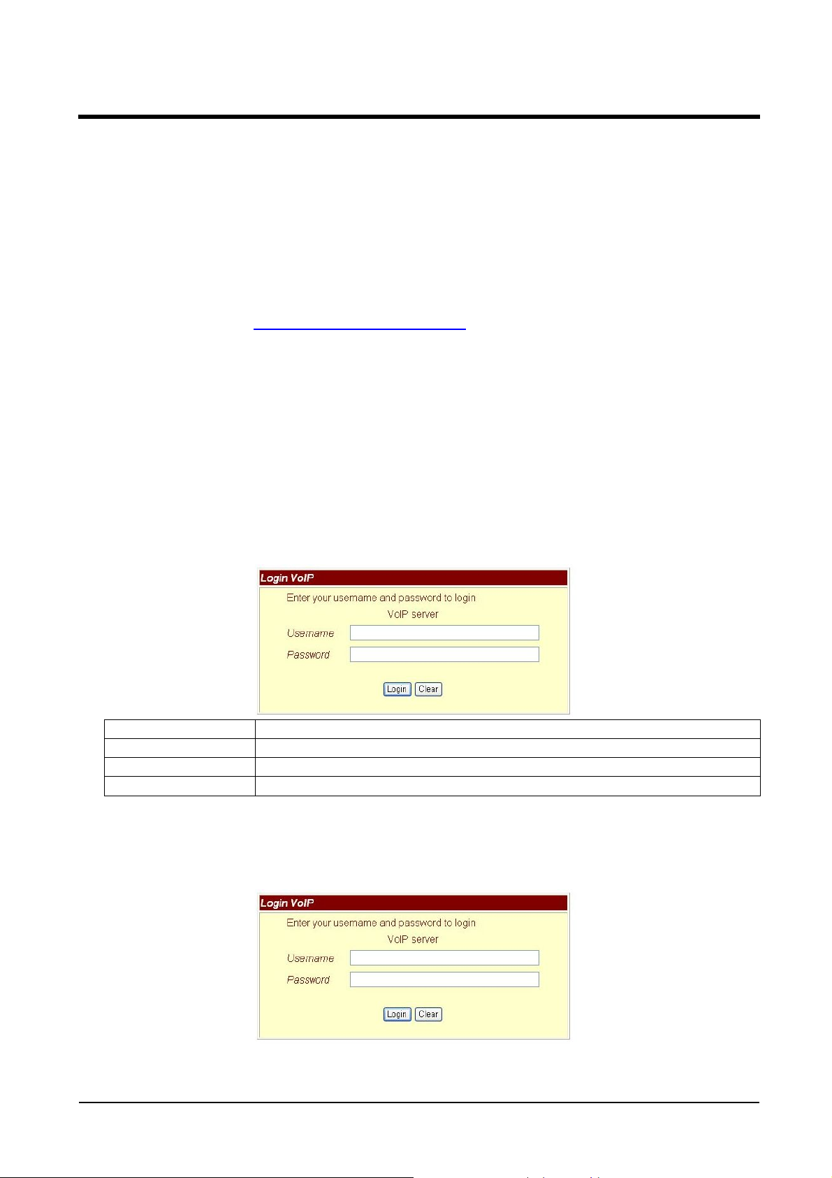
3.2.1 Login VoIP Web Page
Connect PC network line to LAN port, and set PC to auto receive IP mode (DHCP); default the
IP address as of 192.168.123.150.
3.2.1 Function
Provide login system management page.
3.2.2 Instruction
Username Input user’s name, can be numeral or letters.
Password Input password, can be numeral or letters.
Login [Button] Login the system
Clear [Button] Clear all information.
3.2.3 Operate instruction
Step 1: Open IE, input [http://192.168.123.1:9999], and then enter.
Step 2: Login [Login VoIP] page, please input [Username & Password (e.g. Username: root,
Password: test)], then press [Login]. Make sure that the Password is OK (See Figure 1).
(Figure 1)
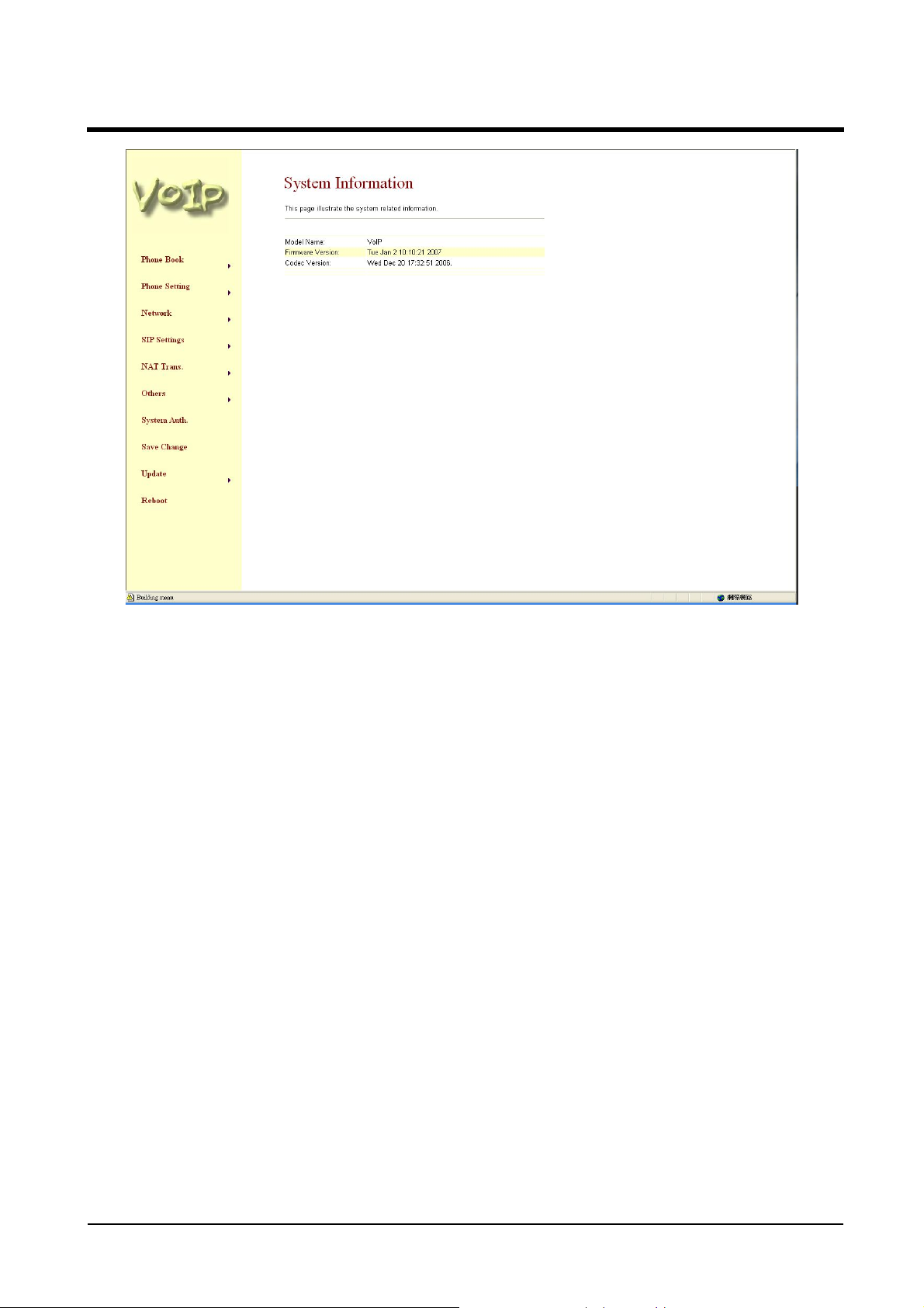
Step 3: After login the system, the System Information will be seen (See Figure 2).
ATA-171/172/171P/171M/171+/172+
User’s Guide
(Figure 2)
3.3.1 VoIP Setting Page
3.3.1 Function
Provide Phone Book, Phone Setting, Network Setting, SIP Setting, NAT, Other
Settings, System Auth, Save, Reboot,
Update, and Reboot.
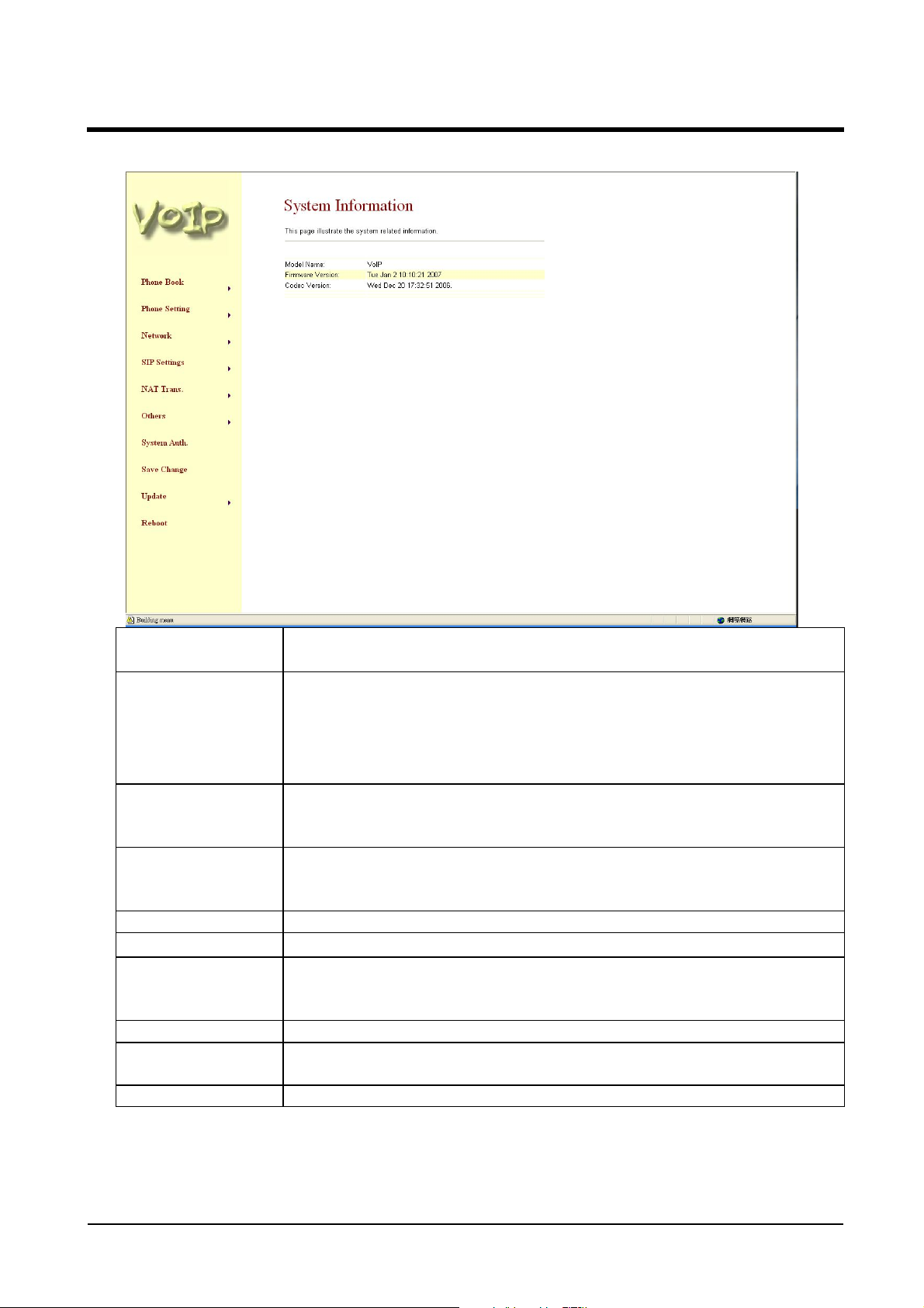
3.3.2 Instruction
ATA-171/172/171P/171M/171+/172+
User’s Guide
Phone Book Phone Book item, provides Phone Book & Speed Dial(for Phone)
【1】
Phone Setting Phone Setting item, provides Forward Setting, SNTP Setting
Volume Setting, DND Setting, Caller ID Setting【2】, Auto Answer
【3】, Dial Plan Setting, Flash Time Setting【2】, Call Waiting
Setting, Soft-Key Setting【1】, T .38 Setting (for FXS)【2】 , Hotline
Setting, Alarm Setting
Network Setting Network Setting item, provides Network Status, WAN Setting,
LAN Setting, DDNS Setting, VLAN Setting, DMZ Setting, Virtual
Server, PPTP Setting.
SIP Setting SIP Setting item, provide Service Domain, Port Settings, Code
Settings, Codec ID Settings, DTMF Settings, RPort Settings,
Other Settings
NA T Tran. NA T Tran, provides STUN Settings.
System Auth
Other Setting Other Setting items provide Auto Config, FXS Port/FXO Port/FXS
Save Save the change.
Update Update items, provides New Firmware, Auto Update, Default
Reboot Reboot, restarted the system.
Notes:
【1】:Phone equipment function。
【2】:FXS equipment function。
【3】:FXO equipment function。
System Auth item, changes user's name or password.
& FXO Port/Phone +FXO Port Setting, MAC Clone Setting, Tone
Setting, Advanced Setting.
Setting
ATA-171/172/171P/171M/171+/172+
User’s Guide
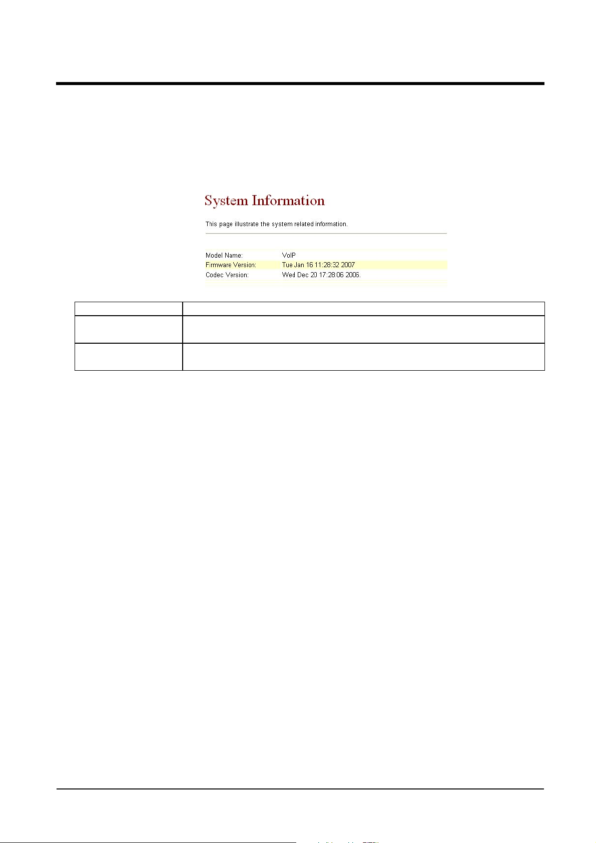
3.4.1 System Information
3.4.1 Function
View Model Name, Firmware Version, Codec Version etc.
3.4.2 Instruction
Model Name Show the name of the equipment
Firmware Version Show the Risc version information, e.g. Tue Jan 16 11:28:32
2007.
Codec Version Show the DSP version information, e.g. Wed Dec 20 17:28:06
2006.

ATA-171/172/171P/171M/171+/172+
User’s Guide
Chapter 4.1 Phone Book
Provide Phone Book, Speed Dial function【1】.
4.1.1 Phone Book
4.1.1 Function
Phone Book can provide 140 entries. When user A calls person B, if person B’s name
is in the phone book, then B’s name will be shown on the phone. If not, B’s phone number
will be seen.
4.1.2 Instruction
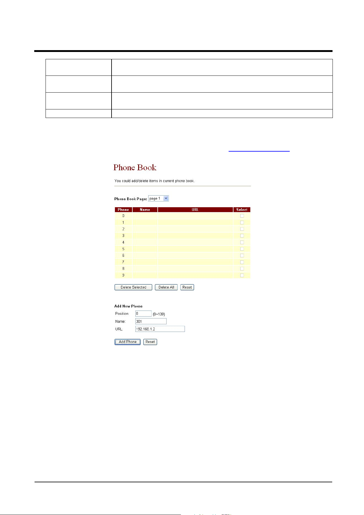
Figure Phone Book
Please Book Page Default: Page 1. Select the page, from Page1~Page14.
Phone Show the serial number. 140 entries in total, from Phone 0~139
Name Show the User’s name.
URL Show the URL information.
Select Select this entry.
Delete Selected
[Button]
Delete All
[Button]
Reset [Button] Reset selected information.
Add New Phone Add new phone book information.
Phone Input serial number, from(0~139) . . Maximum length is 3
Name Input serial number , can be digits or names. M aximum length is
Delete selected information.
Delete all information.
bytes.
ATA-171/172/171P/171M/171+/172+
User’s Guide
31 bytes. Suggest pick up digits, which can be used as
speed dialing numbers.
URL Input Line Number or IP information. Maximum length is 63
bytes.
Add Phone
[Button]
Reset [Button] Delete selected information.
4.1.3 Operate Instruction
Step 1: On the main page, select [Phone BookPhone Book], enter [Phone Book] page,
revise the information (Phone: 0, Name: 301, URL: 301@192.168.1.2
the key [Add Phone] (See Figure 1).
Add this new entry.
), then press
(Figure 1)
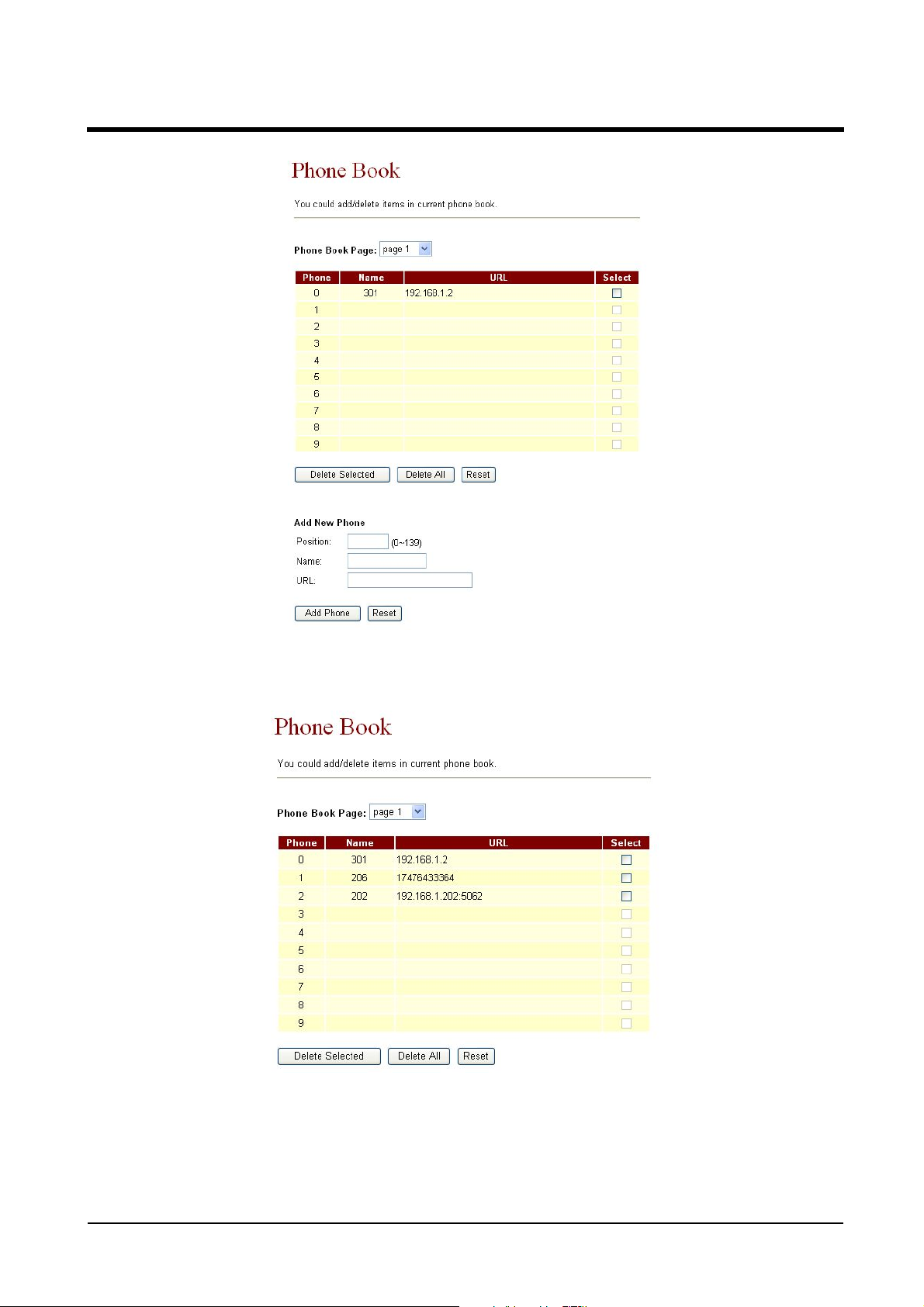
Step 2: After adding the new information (see the table as below), if no information is
added, please save change (See Figure 2).
ATA-171/172/171P/171M/171+/172+
User’s Guide
(Figure 2)
Step 3: After add all information, select [Save Change], enter [Save Changes] page, save the
change. [Note Information] will be seen. Then the system will be restarted automatically,
please wait for a second (See Figure 3).
(Figure 3)
Illustration 1: Name: 301, URL: 301@192.168.1.2.
Application 1: The user pick up the phone, input [301], which, in [Name] column is
[192.168.1.2] that rings
Illustration 2: Name: 206, URL: 17476433364.

ATA-171/172/171P/171M/171+/172+
User’s Guide
Application 1: The user pick up the phone, input [206], which, in [Name] column is
[17476433364] that rings.
Illustration 3: Name: 202, URL: 192.168.1.202:5062.
Application 1: The user pick up the phone, input [202], which, in [Name] column is
[192.168.1.2:5062] that IP: 192.168.1.2 and port 5062 ring.
Application 2: The user pick up the phone, input [0227458080], but no information
is found in [Name] column, so the requirement will be sent directly.
ATA-171/172/171P/171M/171+/172+
User’s Guide
4.2.1 Speed Dial (for Phone)
4.2.1 Function
Speed Dial Phone List can provide 10 entries in total and must be used with Function
Key.
4.2.2 Instruction
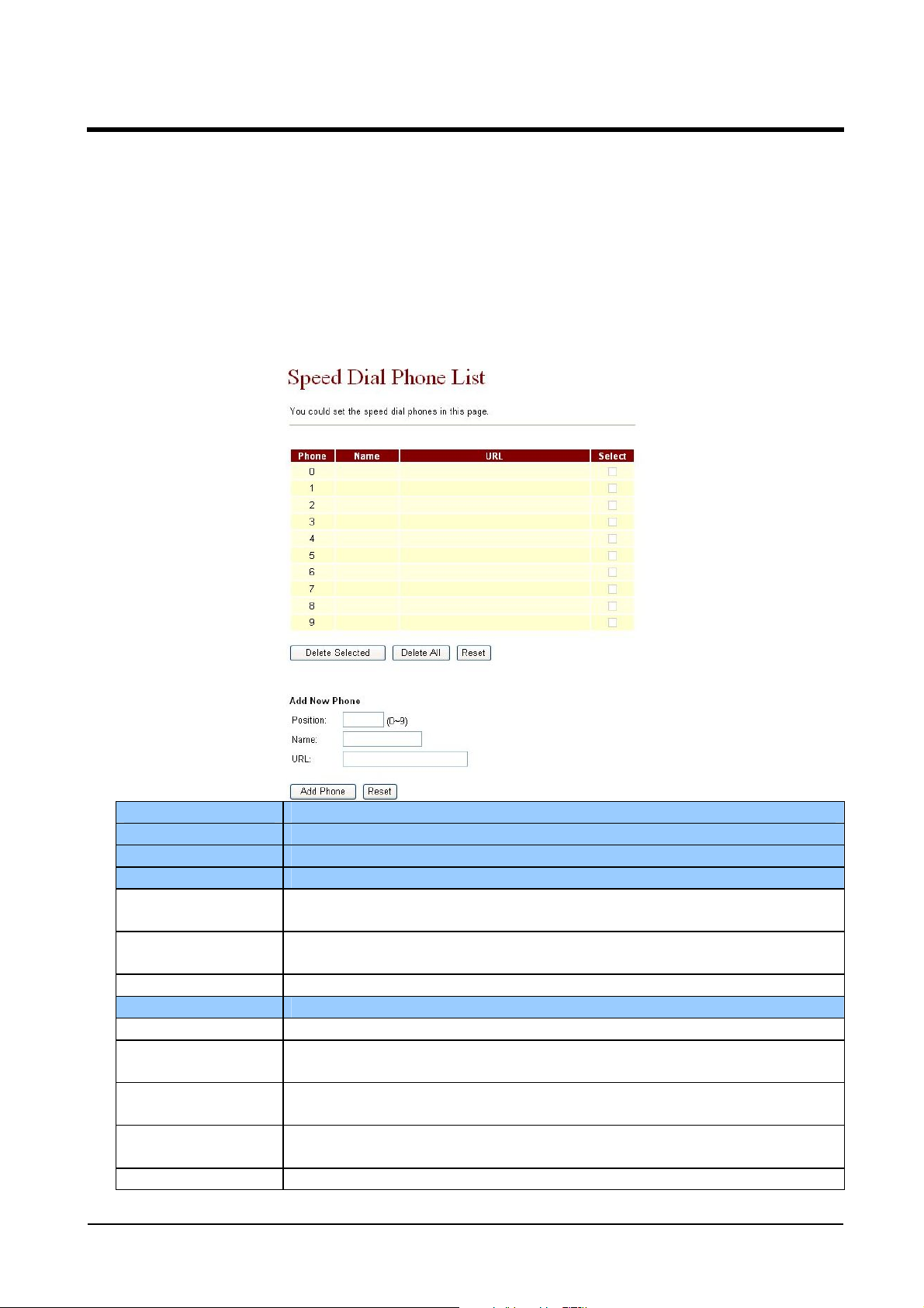
Figure Speed Dial Setting 【1】
There must be corresponding M1 to M10 quick dial function button on the phone
set; otherwise, the quick dial function will be uneffective.
Phone Show the serial number. 10 entries in total.
Name Show the user’s name.
URL Show the URL information.
Select Select the information.
Delete Selected
[Button]
Delete All
[Button]
Reset [Button] Reset selected information.
Add New Phone Add new speed dial phone book information.
Phone Input serial number, from(0~9) . . Maximum length is 1 bytes.
Name Input the code, numbers or names; maximum length is 31
URL Input Line Number or IP information; maximum length is 63
Add Phone
[Button]
Reset [Button] Reset selected information.
Delete all selected information.
Delete all information.
bytes.
bytes.
Add this new entry.

ATA-171/172/171P/171M/171+/172+
User’s Guide
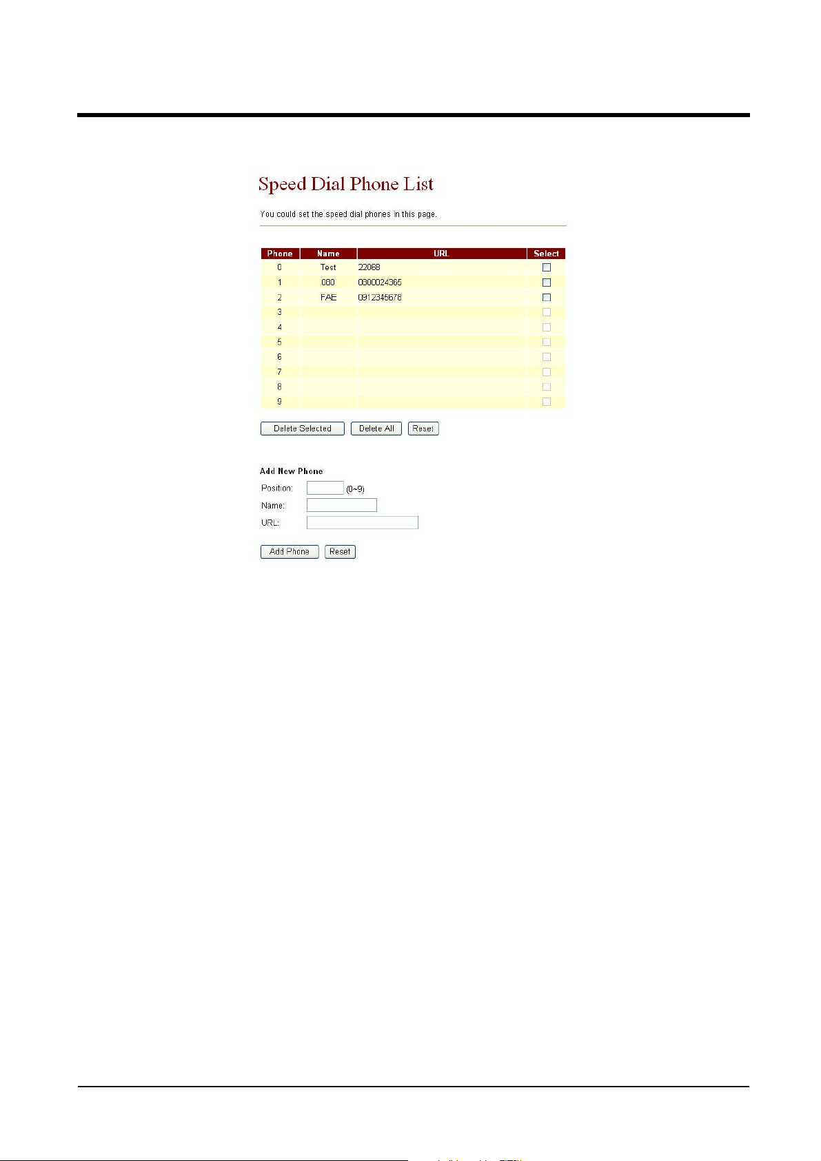
4.2.3 Operate Instruction
Step 1: On the main page, select [Phone BookSpeed Dial], enter [Speed Dial Phone List]
page, after revise the information (Phone: 0, Name: test, URL: 22068) , (Figure 1), press
the [Add Phone] (See Figure 1).
Step 2: After adding all the new information, please save change (See Figure 2).
(Figure 2)
Step 3: After adding all information (See Figure 3), on the main page, select [Save
Change], enter [Save Changes] page, and enforce the command by pressing [Save]. [Note
ATA-171/172/171P/171M/171+/172+
User’s Guide
Information] will be seen when saving successfully, then the system will be restarted
automatically, please wait for a second.
(Figure 3)
Step 4: When using the speed dialing function, please choose the right key (like M2),
then the requirement will be forwarded directly to Phone2: 09123456789.
Notes:
【1】:Phone equipment function。
ATA-171/172/171P/171M/171+/172+
User’s Guide
Chapter 5.1 Phone Setting
Provides Forward Setting, SNTP Setting, Volume Setting, DND Setting, Caller ID
Setting 【2】, Auto Answer【3】, Auto Dial Setting, Dial Plan, Flash Time Setting【2】,
Call Waiting Setting, Soft-K ey Setting【1】, Hotline Setting, Alarm Setting, T.38 Setting
【2】.
5.1.1 Forward Setting
5.1.1 Function
Forward the calling to dedicated phone number. Here provide All Forward, Busy
Forward and No Answer Forward function. Before setting this forward function, please
make sure service providor can support this function.
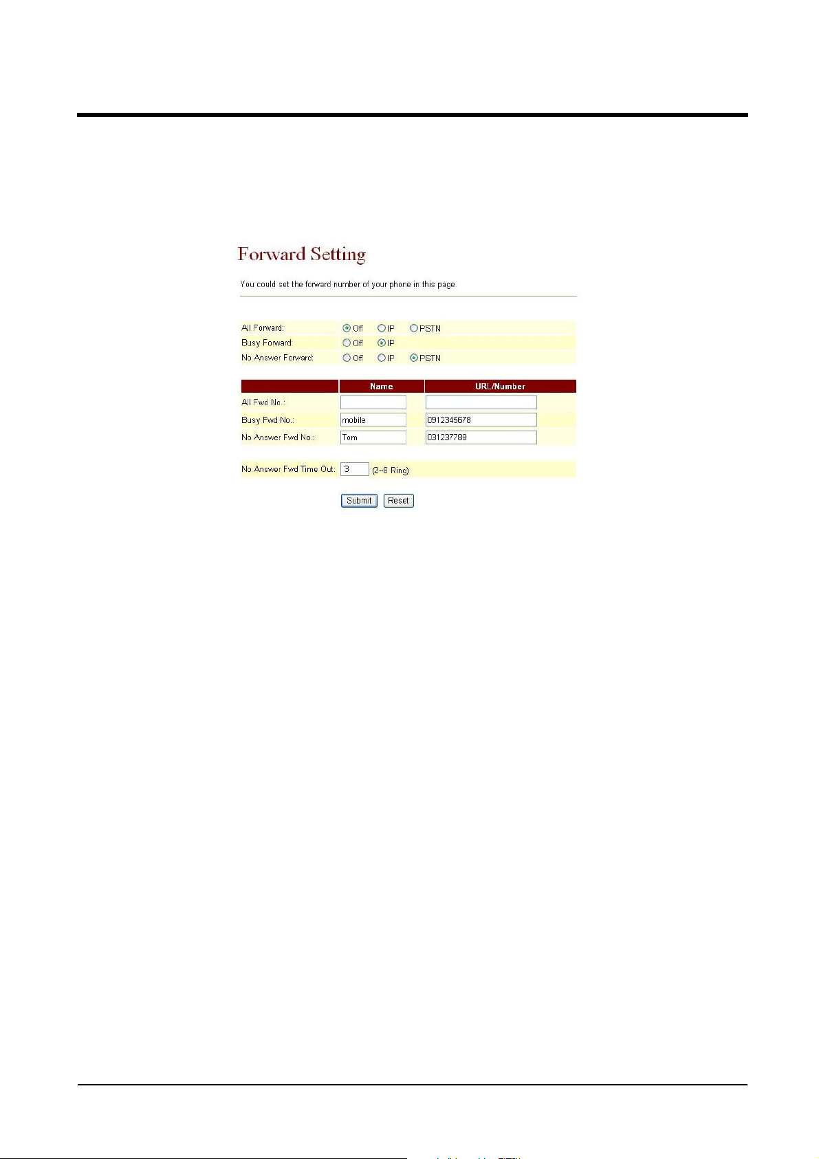
5.1.2 Instruction
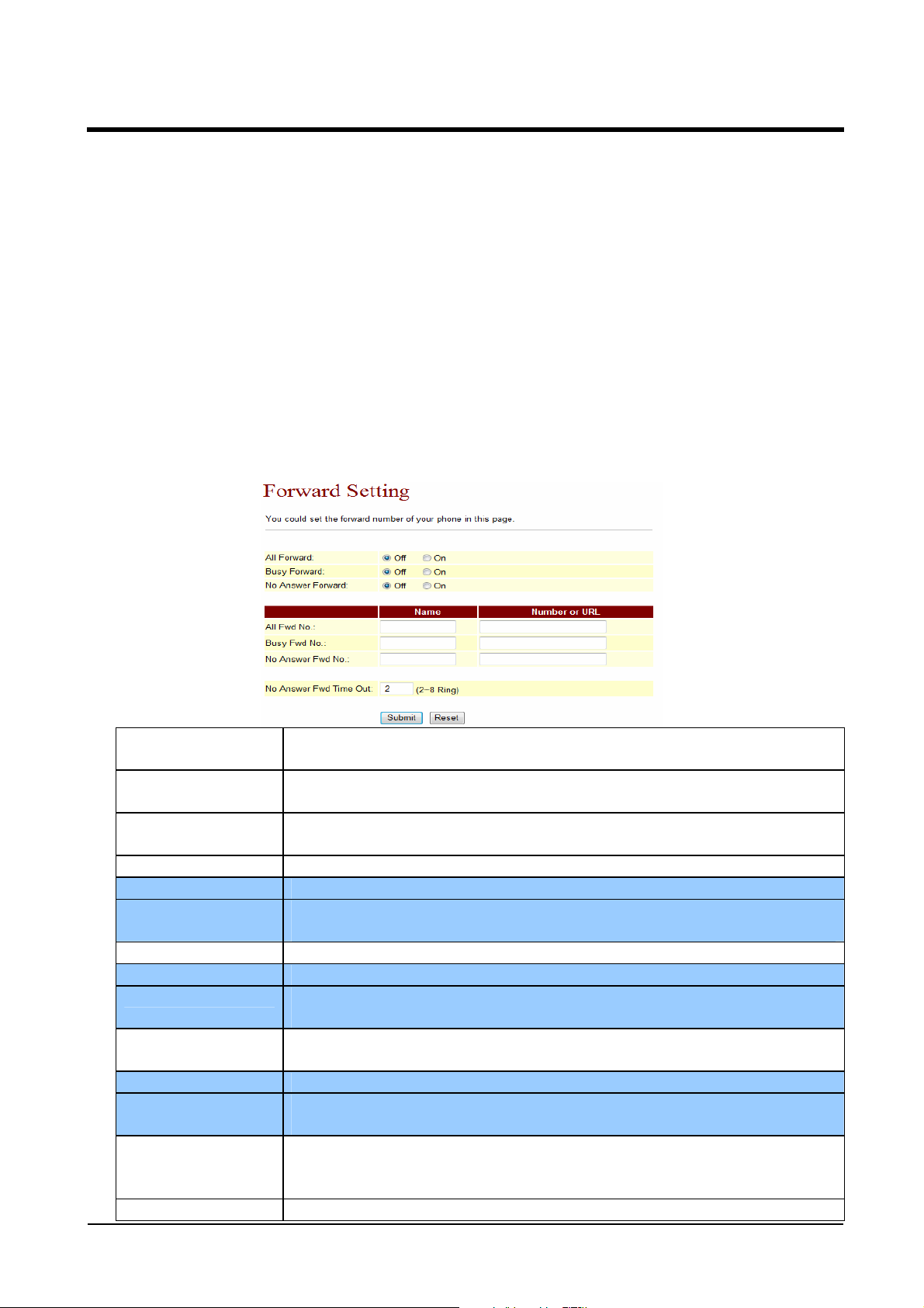
Figure 1: FXS or Phone equipment
All forward Default: Off. When setting On, all incoming calls will be
forwarded, in support of IP mode.
Busy Forward Default: Off. When setting On, and the line is busy, it will run to
support IP mode.
No Answer
Forward
All Fwd No. All incoming calls will be forwarded.
Name Show or Input the name.
URL Number Show or input the dialing information, can be Login Account, IP
Busy Fwd No. Forward the call when line is busy.
Name Show or set the name.
URL Number Show or input the dialing information, can be Login Account, IP
No Answer Fwd
No.
Name Show or set the name.
URL Number Show or input the dialing information, can be Login Account, IP
No Answer Fwd
Time Out
Submit [Button] Enforce the command of saving chance.
Default: off. When setting On and there is no body answer the
phone, it will run to support IP mode.
Address or PSTN Numbers, maximum length is 63 bytes.
Address or PSTN Numbers, maximum length is 63 bytes.
Forward the call when nobody answers the phone.
Address or PSTN Numbers, maximum length is 63 bytes.
Default: 3(Ring), when ringing 3 times but no one answers, it is
regarded as no one answers th e call. Data Range: (2~8 Ring). . .
Maximum length is 2 bytes.
Reset [Button] Delete selected information.
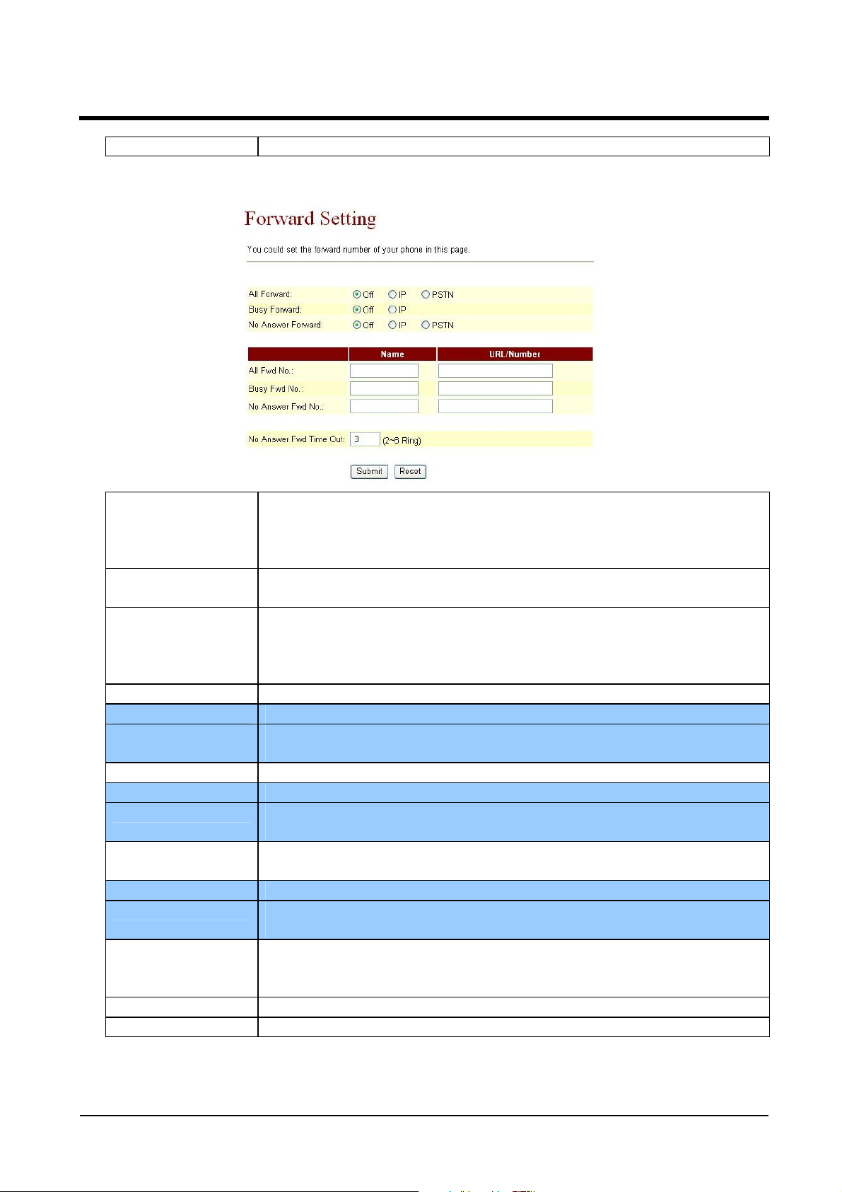
Figure 2: FXS and FXO or Phone and FXO equipment
ATA-171/172/171P/171M/171+/172+
User’s Guide
All forward Default: Off. When setting ON, all the incoming calls will be
forwarded by IP mode or PSTN mode.
NOTICE: If the incoming call goes through FXO, the call
could only be forwarded to IP mode.
Busy Forward Default: Off. When setting On, and the line is busy, the call will
be forwarded only by IP mode.
No Answer
Forward
All Fwd No. All incoming calls will be forwarded.
Name Show or input the name.
URL Number Show or input the dialing information, can be Login Account, IP
Busy Fwd No. Forward the call when line is busy.
Name Show or set the name.
URL Number Show or input the dialing information, can be Login Account, IP
No Answer Fwd
No.
Name Show or set the name.
URL Number Show or input the dialing information, can be Login Account, IP
No Answer Fwd
Time Out
Submit [Button] Enforce the command of saving chance.
Reset [Button] Delete selected information.
Default: Off. When setting On, and nobody answers the phone, it
will run by IP mode or PSTN mode.
NOTICE: If the incoming call goes through FXO, the call
could only be forwarded to IP mode.
Address or PSTN Numbers, maximum length is 63 bytes.
Address or PSTN Numbers, maximum length is 63 bytes.
Forward the call when nobody answers the phone.
Address or PSTN Numbers, maximum length is 63 bytes.
Default: 3(Ring), when ringing 3 times but no one answers, it is
regarded as no one answers the call. Data Range: (2~8 Ring) . .
Maximum length is 2 bytes.
5.1.3 Operate Instruction
Example 1: Forwarded under any condition
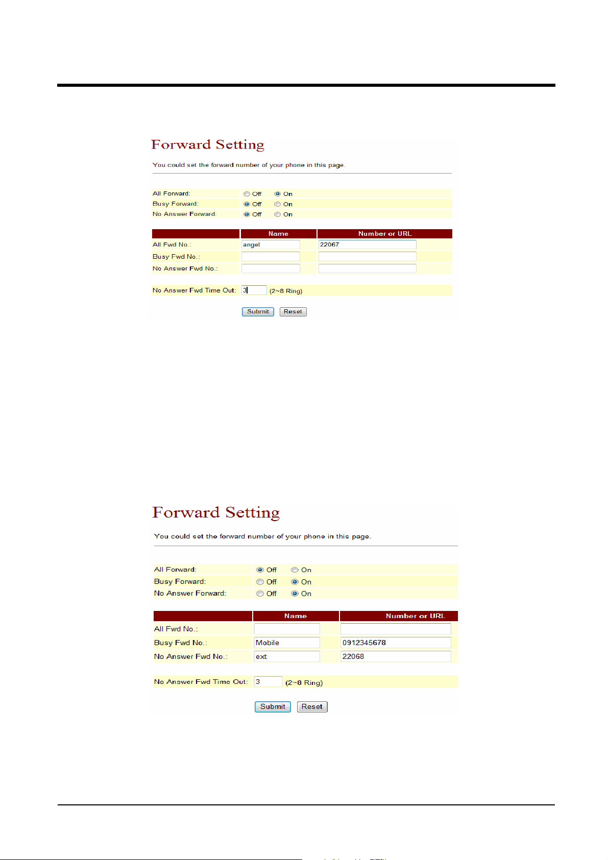
ATA-171/172/171P/171M/171+/172+
User’s Guide
Step 1: On the main page, select [Phone SettingForward Setting], enter [Forw ard Setting]
page, after revising all the information (All Forward: on, All fwd No Name: angel, URL:
22067), press [Submit] (See Figure 1).
(Figure 1)
Step 2: After saving change, enter [Note Information] page, “Note Information” will be seen,
then the changing will come into effect.
Step 3: On the main page, select [Save Change] item, enter [Save Changes] page, and execute
the saving command by press [Save]. [Note Information] page will be seen which means
saving successfully. And the system will be restarted, please wait for a while.
Step 4: When receiving a new incoming call, and it will be forwarded to code [Register
Number: 22067] automatically.
Example 2: Busy Forward or No Answer Forward
Step 1: On the main page, select [Phone SettingForward Setting], enter [Forw ard Setting]
page, after revising all the information (Busy Forward: on, No Answer Forward: on, Busy
fwd No Name: Mobil, URL: 0912345678, No Answer Fwd No Name: ext, URL: 22068) (See
Figure 2), then click [Submit].
(Figure 2)
Step 2: After saving change, enter [Note Information] page, “Note Information” will be seen,
then the changing will come into effect.
Step 3: On the main page, select [Save Change] item, enter [Save Changes] page, and execute
the saving command by press [Save]. [Note Information] page will be seen which means
saving successfully. And the system will be restarted, please wait for a second.
ATA-171/172/171P/171M/171+/172+
User’s Guide
Step 4: When the line is busy, it will forward to Mobile [0912345678], and [0912345678]
rings.
Step 5: When it rings 3 time, and nobody answer the phone, it will forward to [Register
Number: 22068], and Register Account: 22068 rings.
Example 3: All incoming calls will be forwarded to IP
Step 1: On the main page, select [Phone SettingForward Setting], enter [Forw ard Setting]
page, after revising all the information (All Forward: on, All fwd No Name: angel, URL:
0912345678) (See Figure 3), then click [Submit].
(Figure 3)
Step 2: After saving change, enter [Note Information] page, “Note Information” will be seen,
then the changing will come into effect.
Step 3: On the main page, select [Save Change] item, enter [Save Changes] page, and execute
the saving command by press [Save]. [Note Information] page will be seen which means
saving successfully. And the system will be restarted, please wait for a second.
Step 4: When receiving a new call, it will forward to Register Number: 22067] automatically,
and Register Account: 22067 rings.
Example 4: Busy forward to IP
Step 1: On the main page, select [Phone SettingForward Setting], enter [Forw ard Setting]
page, after revising all the information (Busy Forward: on, No Answer Forward: on, Busy
fwd No Name: Mobil, URL: 0912345678, No Answer Fwd No Name: ext, URL: 22068) (See
Figure 4), then click [Submit].

ATA-171/172/171P/171M/171+/172+
User’s Guide
(Figure 4)
Step 2: After saving change, enter [Note Information] page, “Note Information” will be seen,
then the changing will come into effect.
Step 3: On the main page, select [Save Change] item, enter [Save Changes] page, and execute
the saving command by press [Save]. [Note Information] page will be seen which means
saving successfully. And the system will be restarted, please wait for a second.
Step 4: When the line is busy , it will forward to [0912345678], and Mobile [0912345678] rings.
Step 5: When it rings 3 time, and nobody answer the phone, it will forward to [Register
Number: 22068], and Register Account: 22068 rings.
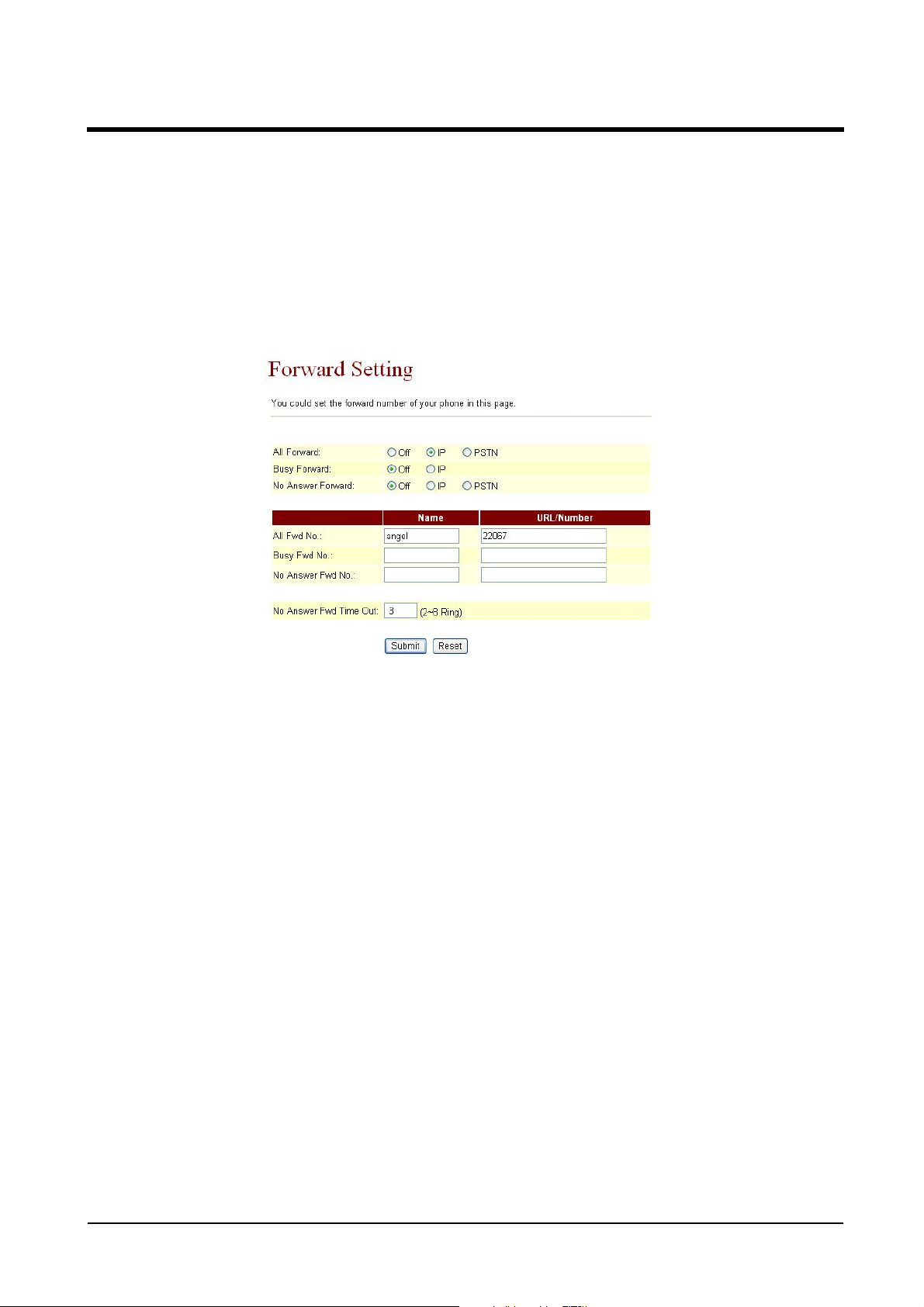
Example 5: All incoming calls will be forwarded to PSTN
Step 1: On the main page, select [Phone SettingForward Setting], enter [Forw ard Setting]
page, after revising all the information (All Forward: PSTN, All fwd No Name: angel, URL:
0912345678) (See Figure 5), then click [Submit].
(Figure 5)
Step 2: After saving change, enter [Note Information] page, “Note Information” will be seen,
then the changing will come into effect.
Step 3: On the main page, select [Save Change] item, enter [Save Changes] page, and execute
the saving command by press [Save]. [Note Information] page will be seen which means
saving successfully. And the system will be restarted, please wait for a while.
Step 4: When receiving a new call, it will run by PSTN Port automatically, and call Mobile
[0912345678]
ATA-171/172/171P/171M/171+/172+
User’s Guide
Example 6: Busy Forward or No Answer Forward to PSTN
Step 1: On the main page, select [Phone SettingForward Setting], enter [Forw ard Setting]
page, after revising all the information (Busy Forward: PTSN, No Answer Forward: on, Busy
fwd No Name: Mobile, URL: 0912345678, No Answer Fwd No Name: ext, URL: 22068)
(See Figure 6), then click [Submit].
(Figure 6)
Step 2: After saving change, enter [Note Information] page, “Note Information” will be seen,
then the changing will come into effect.
Step 3: On the main page, select [Save Change] item, enter [Save Changes] page, and execute
the saving command by press [Save]. [Note Information] page will be seen which means
saving successfully. And the system will be restarted, please wait for a while.
Step 4: When the line is busy , it will forward to [0912345678], and Mobile 0912345678 rings.
Step 5: When rings 3 times and nobody answer the phone, it will run by PSTN Port, and
call PSTN [031237788], and 031237788 rings.
ATA-171/172/171P/171M/171+/172+
5.2.1 SNTP Setting
5.2.1 Function
SNTP Setting can provide the website of time setting for the server.
5.2.2 Instruction
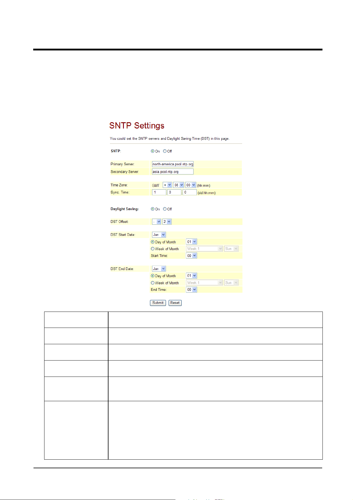
Figure SNTP Setting
User’s Guide
SNTP When setting ON, the SNTP is on; and when setting OFF, the
SNTP is off.
Primary Server Default: time.windows.com; Can input IP or Domain Name,
format is xxx.xxx.xxx.xxx; and the maximum length is 63 digits.
Secondary
Server
Time Zone Default: GMT + 08:00 (hh:mm), and the format is (+/-,
Sync. Time Default: 1:00:00 (dd:hh:mm), it will check the time with th e
DST Satrt Date
Default: 208.184.49.9; can input IP or Domain Name, format is
xxx.xxx.xxx.xxx; and the maximum length is 63 digits.
hh:mm). . . Maximum length is 2 bytes.
Server every other days, format: (dd:hh:mm) . . Maximum
length is 2 bytes.
Set up Daylight Saving Time。You can select the start date by
day or week.
Set up beginning month: Default setting is Jan. Here offer
selection from Jan to Dec.
Day of Month:Default setting is 01. Here provide selection from
1th to 31th.
Week of Month:Select the effective week. Here provide options
ATA-171/172/171P/171M/171+/172+
User’s Guide
for Last Week, Last Second Week, Week1, Week2 and Week3。
Week:Provide options for Sun, Mon, Tue, Wed, Thu, Fri, Sat
Start Time:00; set up effective time。
DST End Date
5.2.3 Operate Instruction
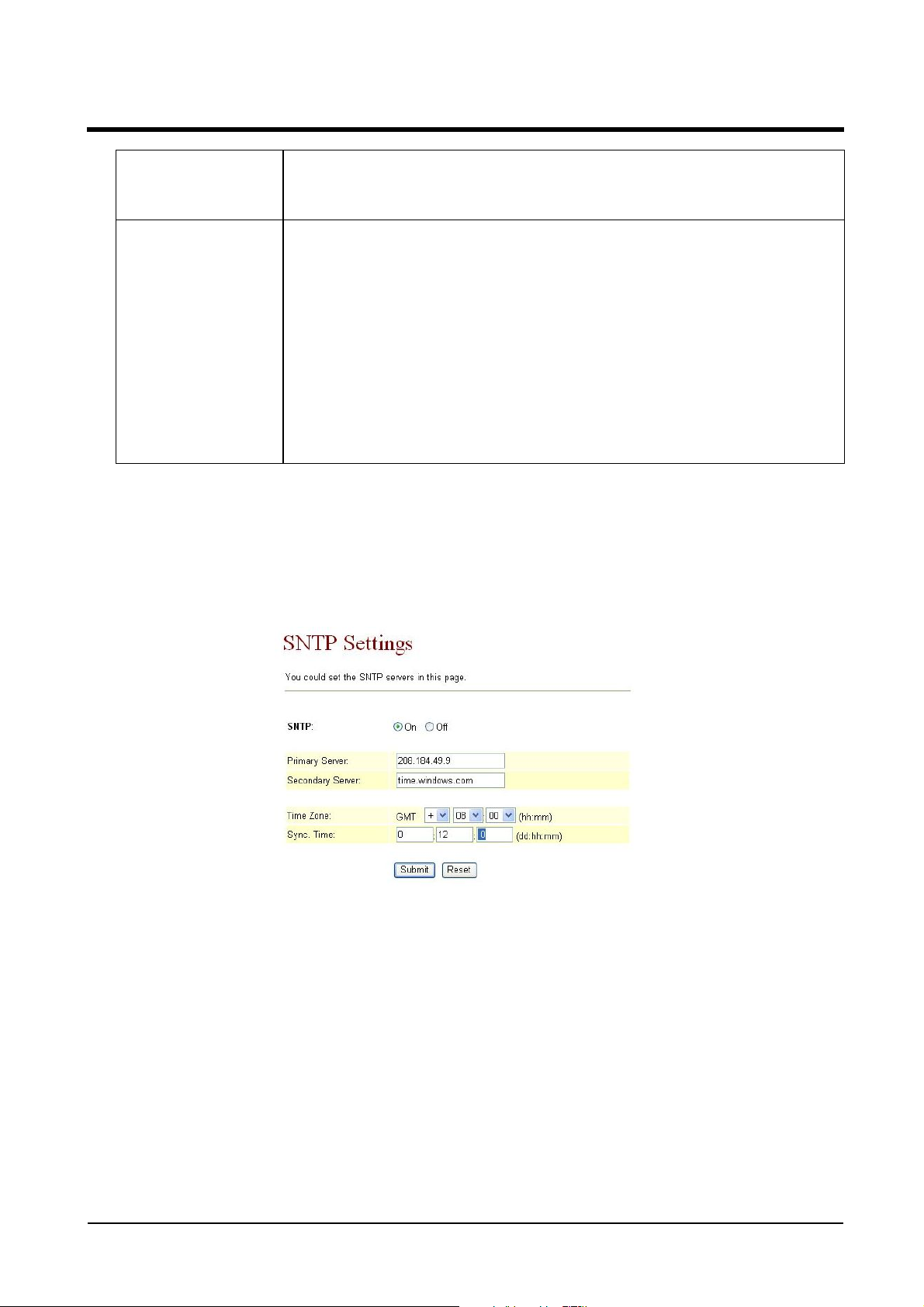
Example 1: Set up SNTP
Step 1: On the main page, select [Phone SettingSNTP Setting], enter [SNTP Setting] page,
after revising all information (e.g. SNTP: on, Primary Server: 208.184.49.9, Secondary
Server: time.windows.com, Time Zone: GMT+08:00, Sync. Time: 00:12:00) (See Figure 1),
then click [Submit].
Stop Daylight Saving Time setting。Y ou can select the stop date
by day or week.
Set up ending month: Default setting is Jan. Here offer selection
from Jan to Dec.
Day of Month:Default setting is 01. Here provide selection from
1th to 31th.
Week of Month:Selec t the effect iv e endi ng week . Here pr ov ide
options for Last Week, Last Second Week, Week1, Week2 and
Week3。
Week:Provide options for Sun, Mon, Tue, Wed, Thu, Fri, Sat
End Time:00; set up effective ending time。
(Figure 1)
Step 2: After saving change, enter [Note Information] page, “Note Information” will be seen,
then the changing will come into effect.
Step 3: On the main page, select [Save Change] item, enter [Save Changes] page, and execute
the saving command by press [Save]. [Note Information] page will be seen which means
saving successfully. And the system will be restarted, please wait for a while.
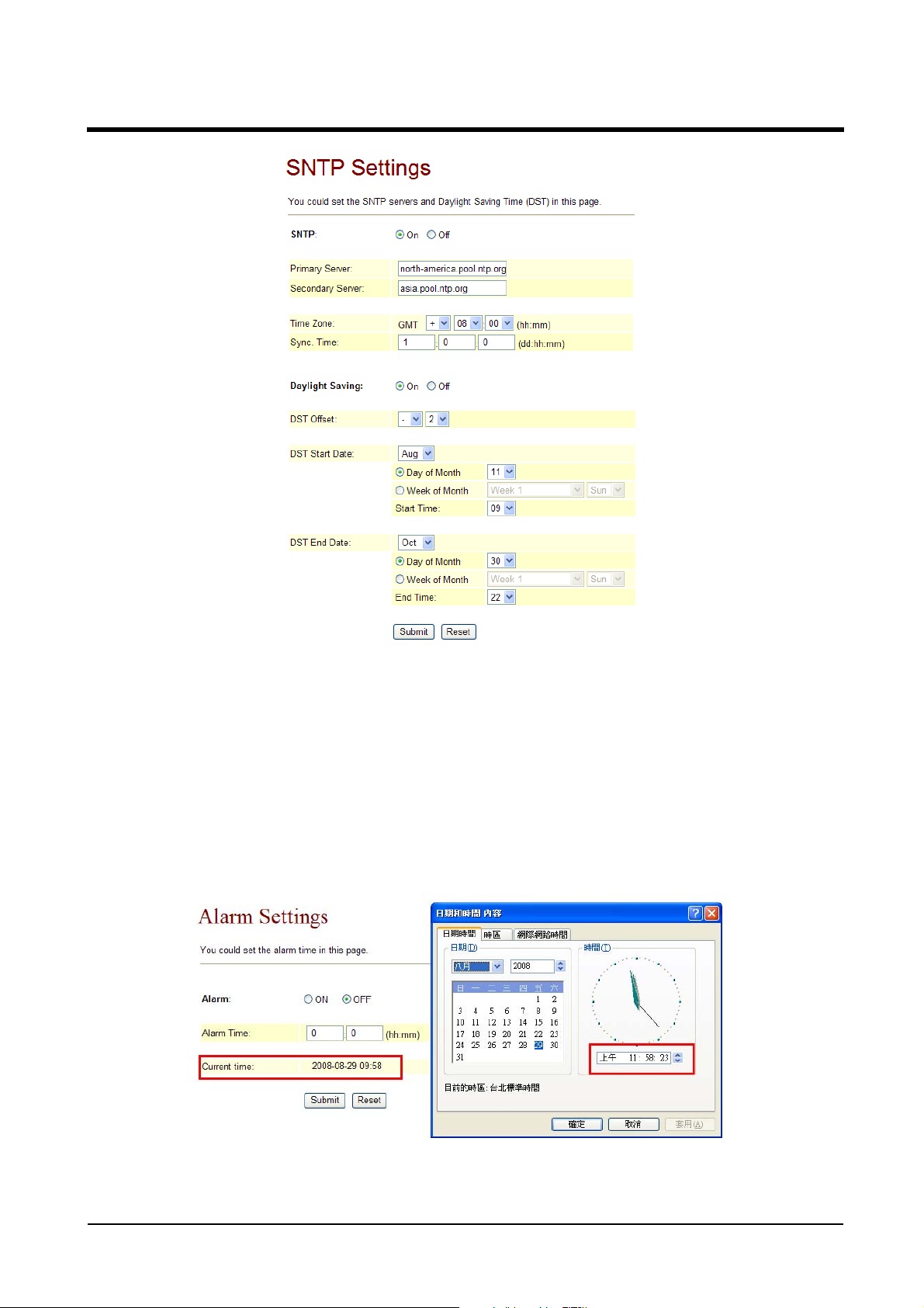
Example 2: Set up Daylight Saving Time (From Aug. 11 to Oct. 30 in each day at 09:00 to
22:00,2-hour delay each day)
Step1: On the main p age ,select [Phone SettingSNTP Setting],enter [SNTP Settings],revise
data (E.g.: Daylingth Saving: On ,DST Offset: -/2 ,DST Start Date: Aug, Day of Month: 11,
St art T ime: 09,DST St art Date: Oct, Day of Month: 30,Start T ime: 22)(See figure 2),press
[Submit] bottom。
ATA-171/172/171P/171M/171+/172+
User’s Guide
(圖 2)
Step 2: After saving change, enter [Note Information] page, “Note Information” will be seen,
then the changing will come into effect.
Step 3: On the main page, select [Save Change] item, enter [Save Changes] page, and execute
he saving command by press [Save]. [Note Information] page will be seen which means
saving successfully. And the system will be restarted, please wait for a second.
Step 4: On the main page, select [Phone Setting Alarm Setting],enter [Alarm Settings]
page to check the time which equipment picked. (Example: Curren Time on equipment is
2008-08-29 09:58 but the time on PC is 11:58)。In figure 3, there are two hours delay in
Alarm Setting.
(圖 3)
ATA-171/172/171P/171M/171+/172+
User’s Guide
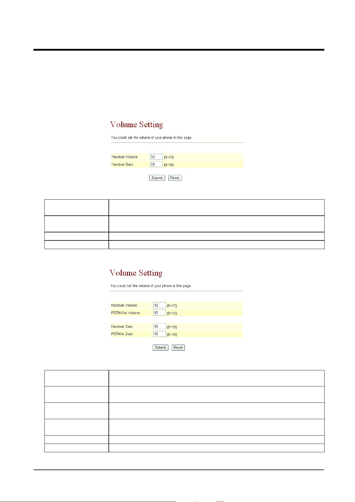
5.3.1 Volume Settings
5.3.1 Function
Volume setting controls the volume of the mic, speaker, and FXO.
5.3.2 Instruction
Figure 1: FXS equipment
Figure 1
Handset Volume Default 10. Control the volume of the Handset from (0~12).
Maximum length is 2 bytes.
Handset Gain Default 10. Control the handset gain from (0~15). Maximum
length is 2 bytes.
Submit [Button] Save the change.
Reset [Button] Clear the change.
Figure 2: FXS+FXO equipment
(Figure 2)
Handset Volume Default 10. Control the volume of the Handset from (0~12).
Maximum length is 2 bytes.
PSTN-Out
Volume
Handset Gain Default 10. Control the Handset Gain from (0~15). Maximum
PSTN-In Gain Default 10. Control the PSTN-In (PSTN Port) Gain from (0~15).
Submit [Button] Submit the change.
Reset [Button] Clear the change.
Default 10. Control the PSTN-Out (PSTN Port) Volume from (0
~12). Maximum length is 2 bytes.
length is 2 bytes.
Maximum length is 2 bytes.
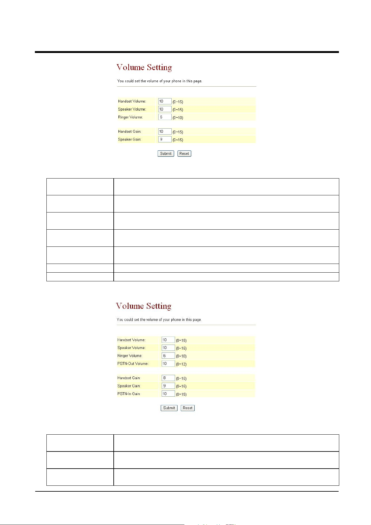
Figure 3: Phone equipment
ATA-171/172/171P/171M/171+/172+
User’s Guide
(Figure 3)
Handset V olume Default 10. Control the Handset Volume from (0~15). Maximum
length is 2 bytes.
Speaker V olume Default 10. Control the Speaker Volume from (0~15). Maximum
length is 2 bytes.
Ringer Volume Default 6. Control the Ringer Volume from (0~10). Maximum
length is 2 bytes.
Handset Gain Default 10. Control the Handset Gain from 0~15. Maximum
length is 2 bytes.
Speaker Gain Default 9. Control the Speaker Gain Volume from 0~15.
Maximum length is 2 bytes.
Submit [Button] Submit the change.
Reset [Button] Clear the change.
Figure 4: Phone equipment
(Figure 4)
Handset V olume Default 10. Control the Handset Volume from (0~15). Maximum
length is 2 bytes.
Speaker V olume Default 10. Control the Speaker Volume from (0~15). Maximum
length is 2 bytes.
Ringer Volume Default 6. Control the Ringer Volume from (0~10). Maximum
length is 2 bytes.
ATA-171/172/171P/171M/171+/172+
User’s Guide
PSTN-Out
Volume
Handset Gain Default 8. Control the Handset Gain Volume from 0~15 . .
Speaker Gain Default 9. Control the Speaker Gain Volume from 0~15. . .
PSTN-In Gain Default 10. Control the PSTN-In (PSTN Port) Gain Volume from
Submit [Button] Submit the change.
Reset [Button] Clear the change.
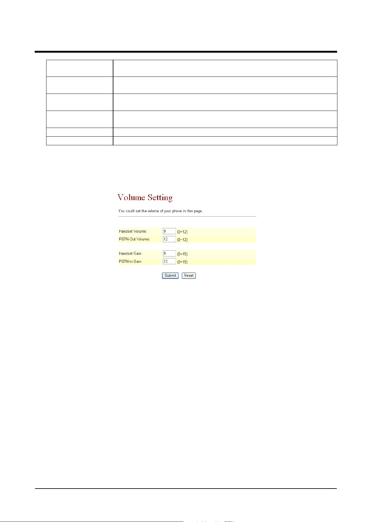
5.3.3 Operate Instruction
Step 1: On the main page, select [Phone Setting Volume Setting], enter [V olume Setting]
page, after revising all information (e.g. Handset Volume: 9, PSTN-Out Volume: 12, Hand
Set Gain: 9, PSTN-In Gain: 13) (See Figure 1), then click [Submit].
Default 10. Control the PSTN-Out (PSTN Port) Gain Volume from
(0~12) . . Maximum length is 2 bytes.
Maximum length is 2 bytes.
Maximum length is 2 bytes.
(0~15) . . Maximum length is 2 bytes.
Step 2: After saving change, enter [Note Information] page, “Note Information” will be seen,
then the changing will come into effect.
Step 3: On the main page, select [Save Change] item, enter [Save Changes] page, and execute
the saving command by press [Save]. [Note Information] page will be seen which means
saving successfully. And the system will be restarted, please wait for a while.
ATA-171/172/171P/171M/171+/172+
User’s Guide
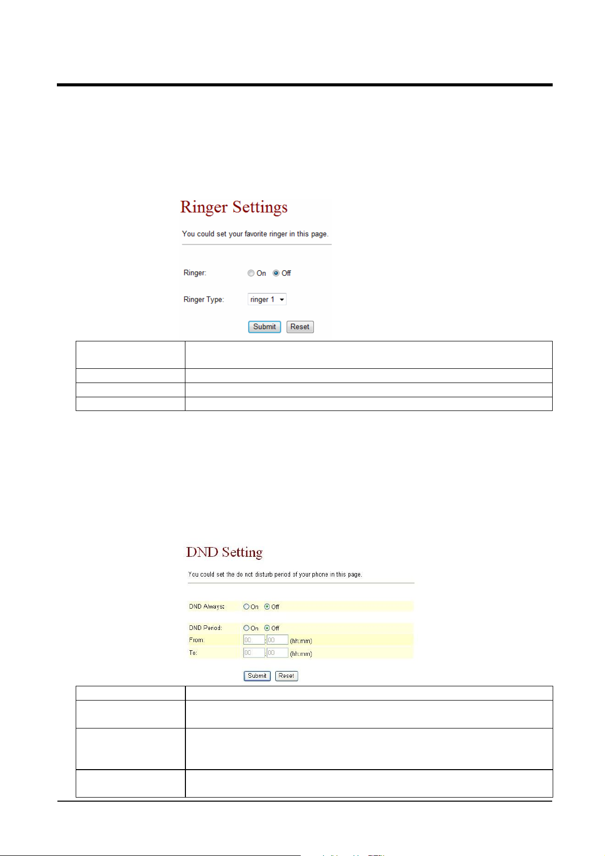
5.4.1 Melody (Melody Setting)
5.4.1 Function
Melody Setting, provide 4 kinds of melody for ring selection.
5.4.2 Instruction
Phone and Phone+FXO equipment
Ringer Default: Off, using standard ring. When setting to On, the
melody of ring can be changed to the melody you select.
Ringer Type Scroll down the ring type.
Submit [Button] Submit the change.
Reset [Button] Clear the change.
5.5.1 DND Setting
5.5.1 Function
DND Setting allows denying all incoming calls or denies all incoming calls in a certain
time period.
5.5.2 Instruction
Figure DND Setting
DND Always Default: OFF. When setting ON, all incoming calls will be denied.
DNS Period Default OFF . When setting ON, all incoming calls will be denied in
pre-setting time period.
From Default: 00:00 (hh:mm), please input the time point that begins
the command. (24h in total, hh:mm) . . Maximum length is 2
bytes.
To Default: 00:00(hh:mm), please input the time point that ends
the command. (24h in total, hh:mm) . . Maximum length is 2
 Loading...