


eMotion LV1 Live Mixer
User Guide Chapter 1
Introduction and Setup
1
LV1

i
Waves eMotion LV1 User Guide | Introduction
Contents
INTRODUCTION ........................................................................................................................... 1
About Waves eMotion LV1 ................................................................................................................................................................. 2
Installation and Setup......................................................................................................................................................................... 4
Host Computer Minimum Requirements ................................................................................................................................................. 6
Connections ............................................................................................................................................................................................. 7
Installing Software ................................................................................................................................................................................... 9
Top Bar ............................................................................................................................................................................................. 10
CHAPTER 1: SETUP WINDOW .................................................................................................... 17
System Inventory Page ..................................................................................................................................................................... 18
System Inventory Page Displays and Controls ........................................................................................................................................ 19
Sample Rate Controls ............................................................................................................................................................................. 20
Device Racks: Configuring and Managing Network Devices .................................................................................................................. 21
I/O Sharing ............................................................................................................................................................................................. 26
Sharing a Device..................................................................................................................................................................................... 27
Patching Shared Devices ........................................................................................................................................................................ 31
Servers ................................................................................................................................................................................................... 36
External Control Devices ........................................................................................................................................................................ 38
Using the System Inventory Page ..................................................................................................................................................... 40
Working Offline...................................................................................................................................................................................... 44
Mixer Settings Page .......................................................................................................................................................................... 45
User Interface Settings Page ............................................................................................................................................................. 51
User-Assignable Menu Items ................................................................................................................................................................. 54
CHAPTER 2: PATCH WINDOW .................................................................................................... 56
Patch Window Sections .................................................................................................................................................................... 57
Filtering Tools ........................................................................................................................................................................................ 58
Patch Views ........................................................................................................................................................................................... 59
Grid Filters ............................................................................................................................................................................................. 59
Navigating the Grid Filters...................................................................................................................................................................... 59

ii
Waves eMotion LV1 User Guide | Introduction
The Patch Grid ................................................................................................................................................................................. 60
Mixer Channels, Mix Busses and Control Groups ................................................................................................................................... 62
Mixer Inputs .......................................................................................................................................................................................... 64
Mixer Outputs ........................................................................................................................................................................................ 65
Internal Routing ..................................................................................................................................................................................... 66
Device-to-Device .................................................................................................................................................................................... 67
CHAPTER 3: CHANNEL WINDOW ............................................................................................... 69
Channels and Presets ....................................................................................................................................................................... 71
Channel Presets ..................................................................................................................................................................................... 71
Copying Channel Information................................................................................................................................................................. 73
Channel Window Sections ................................................................................................................................................................ 75
Input Section .................................................................................................................................................................................... 76
Preamp Controls .................................................................................................................................................................................... 78
Controlling Preamp Gain on Shared Devices .......................................................................................................................................... 81
Input Section for Mix Channels .............................................................................................................................................................. 83
Plugin Rack Section .......................................................................................................................................................................... 86
Adding and Managing Plugins .......................................................................................................................................................... 87
The Plugin Menu .................................................................................................................................................................................... 87
Plugin Menu: Plugins Section ................................................................................................................................................................. 88
Plugin Menu: Presets Section ................................................................................................................................................................. 90
Plugin Menu: Latency Section ................................................................................................................................................................ 90
Plugin Pane ...................................................................................................................................................................................... 93
Main Control Section ........................................................................................................................................................................ 95
Assigning a Plugin to the Dynamics, EQ, and Filter Controls ................................................................................................................... 96
Dynamics Mapping in the Main Control Section ................................................................................................................................... 97
EQ Plugin Controls in the Main Control Section ...................................................................................................................................... 98
AUX/EFX and AUX/MON Sends Section .......................................................................................................................................... 101
Aux Sends ............................................................................................................................................................................................ 102
Channel Output Section ....................................................................................................................................................................... 105
Cue ...................................................................................................................................................................................................... 110

iii
Waves eMotion LV1 User Guide | Introduction
Talkback ......................................................................................................................................................................................... 113
Matrix ............................................................................................................................................................................................ 115
Link Channel Controls (DCAs) ......................................................................................................................................................... 118
CHAPTER 4: MIXER WINDOW .................................................................................................. 120
Top Bar ........................................................................................................................................................................................... 126
Mixer Layers ................................................................................................................................................................................... 127
Channels Layer ..................................................................................................................................................................................... 128
Groups Layer........................................................................................................................................................................................ 129
Aux Layer ............................................................................................................................................................................................. 130
Masters Layer ...................................................................................................................................................................................... 132
Buss Outs ............................................................................................................................................................................................. 133
Link/DCA Layer..................................................................................................................................................................................... 135
ALL Layer ............................................................................................................................................................................................. 137
Custom Layers ..................................................................................................................................................................................... 138
Dugan Layer ......................................................................................................................................................................................... 139
Basic Operation.................................................................................................................................................................................... 139
MIXER CHANNELS ........................................................................................................................................................................... 140
Channel Strip ....................................................................................................................................................................................... 140
Channel Input ...................................................................................................................................................................................... 141
Pan/Balance/Rotate Functions ............................................................................................................................................................. 143
Layer Modes ................................................................................................................................................................................... 144
Input Layer Mode ................................................................................................................................................................................ 146
Dynamics/EQ Mode ............................................................................................................................................................................. 147
Rack Mode ........................................................................................................................................................................................... 148
Route Mode ......................................................................................................................................................................................... 151
Aux Modes (AUX/EFX, AUX/MON, ALL AUX)......................................................................................................................................... 152
Sends on Faders ................................................................................................................................................................................... 153
Channel Mode ..................................................................................................................................................................................... 155
Master Fader .................................................................................................................................................................................. 156
Utility Sections ............................................................................................................................................................................... 157
Link Group Controls ............................................................................................................................................................................. 159

iv
Waves eMotion LV1 User Guide | Introduction
CHAPTER 5: SHOW WINDOW .................................................................................................. 162
Sessions Page ................................................................................................................................................................................. 163
Sessions List ......................................................................................................................................................................................... 165
Loading a Session ................................................................................................................................................................................. 166
Templates ............................................................................................................................................................................................ 168
Auto-Saving Sessions ........................................................................................................................................................................... 168
Scenes Page.................................................................................................................................................................................... 170
Scenes List ........................................................................................................................................................................................... 172
Hot Scenes ........................................................................................................................................................................................... 174
Scope Section ................................................................................................................................................................................. 175
Channel Parameters............................................................................................................................................................................. 176
Scope of Changes: Session vs. Scene .................................................................................................................................................... 177
Recall Safe Page ................................................................................................................................................................................... 178
CHAPTER 6: eMotion LV1 SIGNAL FLOW DIAGRAMS............................................................... 180
APPENDIX A: eMOTION LV1 MIXER CONFIGURATIONS ................................................................................................................... 190
APPENDIX B: USING MULTIPLE DISPLAYS ........................................................................................................................................ 192
APPENDIX C: INCORPORATING MIDI ............................................................................................................................................... 200
APPENDIX D: MACKIE CONTROL PROTOCOL ................................................................................................................................... 203
APPENDIX E: DELAY GROUPS .......................................................................................................................................................... 210
eMotion LV1 KEYBOARD SHORTCUTS ............................................................................................................................................. 215
1
Waves eMotion LV1 User Guide | Introduction
INTRODUCTION
Thank you for choosing the eMotion LV1 live mixer from Waves. In order to efficiently set up and use the mixer, please become familiar
with the eMotion LV1 manual, which is divided into two parts:
•
A Quick Start Guide that explains navigation, workflow, and basic controls. It provides what you need for initial setup and basic use.
•
This User Guide is a complete inventory of the mixer’s controls and displays, along with in-depth instructions.
We suggest that you visit the Waves support site: http://www.waves.com/support. There you will find an extensive answer base, the
latest tech specs, detailed installation guides, software updates, and much more.

2
Waves eMotion LV1 User Guide | Introduction
About Waves eMotion LV1
Waves eMotion LV1 is a software mixer that provides real-time audio mixing and processing for front-of-house, monitor, broadcast, and
recording studio applications. A mixer system consists of the eMotion LV1 application, a SoundGrid server, and one or more SoundGrid
I/Os. There are three mixer configurations—64, 32 or 16 channels—with up to 8 stereo groups, 16 stereo auxes, L/R/C/M Main busses,
and an 8 stereo channel matrix. The mixer is very scalable and it provides a complete solution for live mixing, from the smallest gig to the
largest production.
The mixer is compatible with Windows and Mac operating systems. It supports industry-standard control surfaces and multi-touch
devices and can run on multiple screens in both wired and wireless networks. This allows you to design your work environment however
you want. Whether you’re using a single laptop with a mouse or multiple touchscreens and control surfaces, the eMotion LV1 user
interface will feel familiar and intuitive.
Powered by low-latency Intel-based Waves SoundGrid DSP servers, eMotion LV1 utilizes the SoundGrid network for connecting
multiple mixers, stage boxes, I/O interfaces, playback/recording hosts, and all other SoundGrid-compatible devices. This provides for
flexible configurations with standard network components.
eMotion LV1 is a one-stop shop for all of your live mixing needs. With eight inserts on each channel for SoundGrid-compatible Waves and
third-party plugins, eMotion LV1 saves you the need to use outboard gear for top-tier processors. eMotion LV1 also lets you share plugin
presets and rack processing chains between your studio and any other platforms or consoles that run MultiRack.

3
Waves eMotion LV1 User Guide | Introduction
About This User Guide
Window
The most comprehensive view (Mixer window, Show window, etc.). Windows are accessed with tabs at the
top of each view.
Page
A subset of a window, usually accessed by a side tab (User I/O Settings, Channels Input A, Scenes, etc.).
Section
An area of a page, usually defined by function (Output section, Channel aux sends section, etc.).
Control
Any object used to change a parameter (fader, knob, button, etc.).
Value Box
A window that displays a parameter and can usually be used to adjust parameter values.
Selected
(1) A control that is currently active. Touch a control to select it. It will change color or become highlighted.
(2) A channel currently being controlled. To select a channel, click on its fader or its name on the channel
strip, or use the navigation tools on the Top Bar.
This User Guide provides detailed information on all eMotion LV1 functions and controls. Like the mixer itself, the User Guide is
organized first by Window, then by Page or Tab, and finally by Section and Controls.
Naming Conventions:
eMotion LV1 supports several input devices: touchscreen monitor, touchscreen panel, external controller, and mouse. These
devices may use different terms for input action, so for simplicity, we use the term “click” to describe all such actions.
Throughout the manual there are references to other sections of the mixer.
• When a control or function is discussed more comprehensively elsewhere in this user guide, there is a reference to that section. A
name set in italics refers to a place in this manual where more detailed information can be found (e.g., see Patch chapter >
Channel Direct Outputs).
• References in roman type refer to a window, page, or section of the mixer interface.
To indicate the location of a control or menu, the manual uses this notation: Window > Page > Section (e.g., Setup window > System
Inventory page > Device Racks section).
To keep things short, the eMotion LV1 mixer is usually referred to as “the mixer.”

4
Waves eMotion LV1 User Guide | Introduction
Installation and Setup
Setting up the mixer consists essentially of these steps. Relevant mixer views are noted here in parentheses:
•Set up hardware
•Download and install software. Activate licenses for eMotion LV1 and plugins (via the Waves Central application)
•Create a session based on templates from previous sessions, or use a blank session template (Show > Sessions)
•Assign and configure all I/O devices (Setup > System Inventory)
•Patch audio between devices and within the mixer (Patch > Input)
Once you’ve created a session, configuring the mixer is similar to setting up other digital consoles:
•Set mixer preferences (Setup > Mixer Settings > U/I Settings)
•Adjust preamps and other inputs (Mixer, Channel)
•Assign groups, links, and adjust sends (Mixer, Channel)
•Assign matrix and mute groups (Mixer, Channel)
•Configure plugins (Channel)
•Create scenes (Show > Scenes)
eMotion LV1 can mix multiple inputs in multiple mix busses and process a large number of plugin instances. To make this possible, all
processing is carried out on a high-speed server, not on the host computer. This server is part of a Waves SoundGrid network, so the
first step in setting up the mixer is to set up the network.
5
Waves eMotion LV1 User Guide | Introduction
1
2
3
4
2
3
4
1
4
4
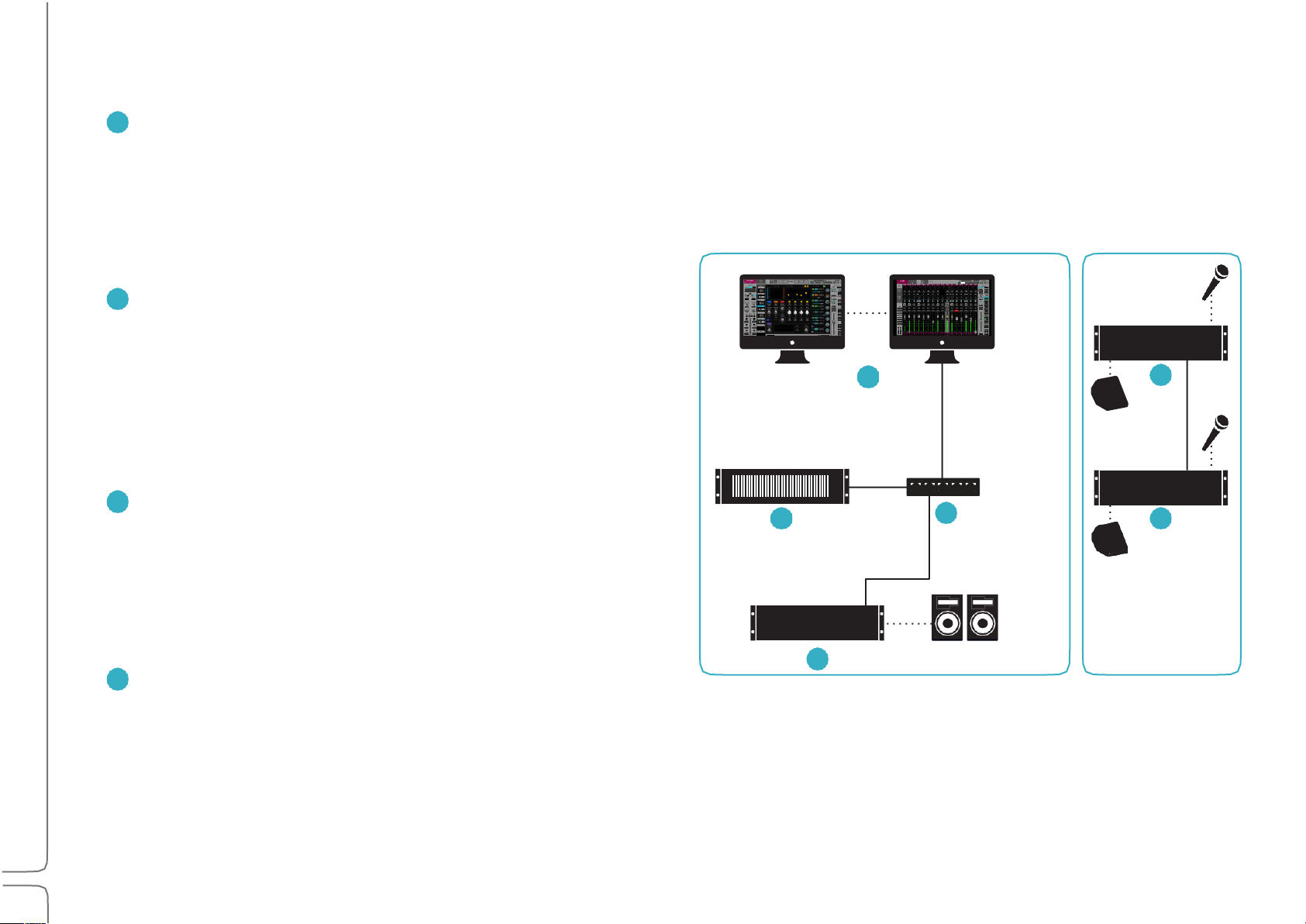
A SOUNDGRID NETWORK CONSISTS OF AT LEAST THESE FOUR HARDWARE ELEMENTS:
HOST COMPUTER: Controls the mixer as well as the SoundGrid
network that connects all devices. The eMotion LV1 application,
plugins, and preset files are located here. However, audio is not
processed here. The mixer application and the SoundGrid network
software run on both Mac and Windows and can support multiple
displays.
SOUNDGRID SERVER: The mixer’s “number cruncher.” All plugin
processing is offloaded from the host computer to the server.
The speed of the server has a direct impact on the number of
SoundGrid channels and plugin instances. There are a number of
server configuration options. Visit www.waves.com/hardware for
up-to-date specifications and requirements about severs and
other hardware components.
SOUNDGRID 1GB ETHERNET SWITCH: Links the I/O devices, server,
and host computer. There is a growing list of SoundGrid-approved
third-party Ethernet switches. Note the model and version of the
FOH Stage
switch you purchase: some versions work well, others don’t.
To ensure compatibility, we advise that you obtain Ethernet
switches through Waves.
AT LEAST ONE SOUNDGRID I/O DEVICE: All I/O devices are connected
via Ethernet, regardless of the number of channels. I/Os range from
2-channel preamps to 128-channel MADI interfaces.
6
Waves eMotion LV1 User Guide | Introduction
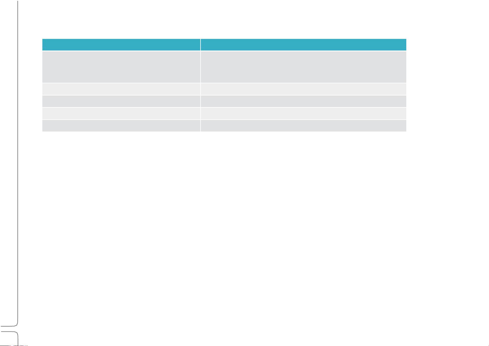
Host Computer Minimum Requirements
Mac OS
Windows
Model/CPU:+Mac Pro 4,1 or higher
MacBook Pro / iMac / Mac
Mini with Intel i5 CPU or higher
CPU: Intel i3 or higher
RAM: 6 GB
RAM: 8 GB
Operating+System: 10.10.5 to 10.13.x
Operating+System: Windows 8.1 / Windows 10 64-bit
Screen+Resolution:+1280x768 32-bit
Screen+Resolution:+1280x768 32-bit
Tablets:+Windows 8.1 / Windows 10 64-bit with Intel processor
Sample Rate Support
The eMotion LV1 mixer supports sample rates of 44.1 kHz to 96 kHz.
All Waves plugins support sample rates of up to 96 kHz; many support higher sample rates. Visit www.waves.com/support for details.
7
Waves eMotion LV1 User Guide | Introduction
Connections
Node
Cable Length
Host computer to main switch
up to 100 meters
Server to main switch
up to 20 meters
Main switch to secondary switch
up to 100 meters
I/O device to main switch
up to 100 meters
I/O device to secondary switch
Up to 20 meters
LV1 can assign and patch to up to 16 I/O devices: any combination of hardware I/Os and drivers.
• A hardware I/O device can have up to 128 I/O channels, depending on the model.
• Computers using a SoundGrid ASIO/Core Audio driver can be configured for up to 128 driver channels.
Use a SoundGrid Ethernet switch and Cat 5e, Cat 6, or Cat 7 Ethernet cables to connect all hardware components. Note which of the host
computer’s Ethernet ports is being used for the SoundGrid network. This port can be used only for the SoundGrid network. Do not attach
an Internet or other network connection to the Ethernet switch. Use another port for these purposes.
MAXIMUM CABLE LENGTHS
Cat 5e/6/7 S/FTP
Cat 5 cables are not supported.
Joints, or cable extenders, can be used, but with care, since some models do not have electrically connected shielding. Using such
extenders in areas with interference may be problematic. Total cable length with the joint may not exceed the above maximum cable
length per node. Additional joints may reduce the effective cable runs.

8
Waves eMotion LV1 User Guide | Introduction
SERVER REQUIREMENTS
All SoundGrid-approved servers will work with the eMotion LV1 mixer. Server performance has a direct impact on processing power and
on the number of mixer channels that can be played simultaneously. Check Waves.com or contact customer support to determine which
server best suits your needs.
DISPLAY RESOLUTION
The suggested display resolution is 1280x768. The mixer can accommodate one, two, or more computer displays. For details please
refer to Appendix B: Using Multiple Displays and consult the manufacturer of your video card and displays.
CONTROL
eMotion LV1 can be controlled in any of these methods:
• 5-point (or more) multi-touch interface
• Control surface supporting Mackie Control™ protocol
• MIDI controller
• Mouse/keyboard

9
Waves eMotion LV1 User Guide | Introduction
Installing Software
Create a free Waves account if you don’t already have one (www.waves.com/create-account). This account is used to manage your
Waves products and licenses.
1. Register your Waves Products in your Waves account under ‘”Register New Products.” The product serial number (also called a
license number) can be found on your purchase invoice, in an email from your dealer, or in an envelope containing the registration
form. Once your registration is complete, a product license will be deposited in your license cloud.
2. Download Waves Central from the Waves website. Waves Central is an application for downloading, installing, and managing the
licenses of Waves software.
3. Download and install the eMotion LV1 mixer and any selected plugins. Next, move your licenses from your license cloud to the
computer you are using or to a USB flash drive.
4. If the host computer on which you’ll be running eMotion LV1 is not connected to the Internet, you can create an offline installer.
Learn more about Waves Central at www.waves.com/support.
5. Launch eMotion LV1.
WINDOWS USERS:
The Widows Power Plan must be set to High Performance.
Open the Control Panel\Hardware and Sound\Power Options window. Select the High Performance plan and re-launch
eMotion LV1.
10
Waves eMotion LV1 User Guide | Introduction
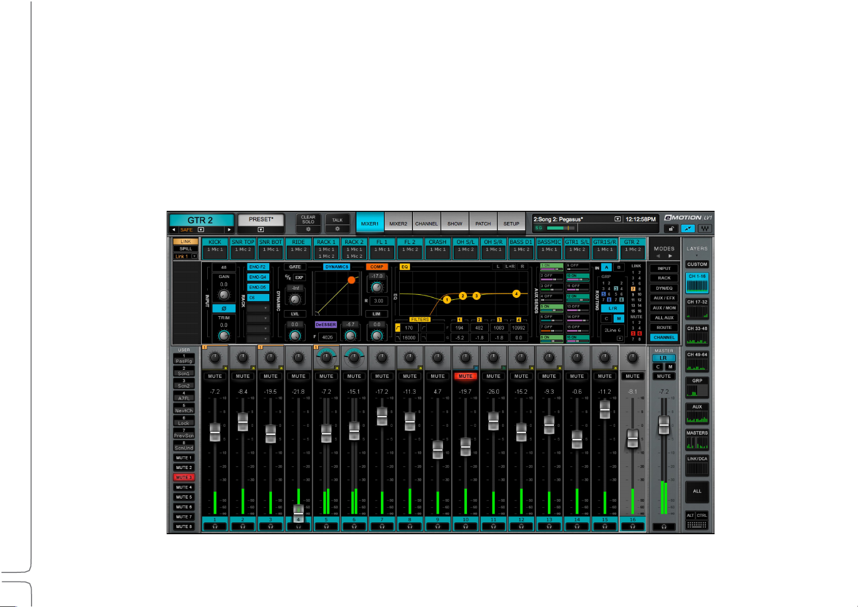
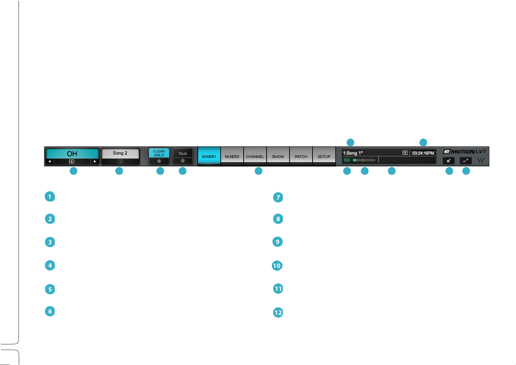
Top Bar
1
Name: Displays the selected channel
7
DSP meter: Displays average and peak processing loads
2
Presets Menu: Manages channel presets and sessions
8
Scenes: Stores and recalls scenes
3
Clear Solo: Clears all solos or cues / accesses cue controls
9
Messages: Reports status and errors
4
Talk: Engages talkback / accesses the TB control page
10
Clock: Displays current MTC position
5
Window select tabs: Navigates to all mixer windows
11
Lock: Locks mixer surface, I/O routing, and/or plugins rack
SG (SoundGrid): Reports the status of the SoundGrid network
12
Full screen mode: Fits the mixer window to full-screen view
8
10
1 2 3 4 5 6 7 9 11 12
The Top Bar of the eMotion LV1 mixer is a navigation and management tool visible from all views. From here you can:
• Access all windows.
• Monitor network and processor status.
• Select a channel.
• Lock the mixer interface.
• Manage sessions and scenes.
• Engage talkback and clear all solos.
11
Waves eMotion LV1 User Guide | Introduction
TOP BAR ELEMENTS
AME
N
This box displays the name of the selected channel. Side arrows move the channel selection higher or lower,
one channel at a time. The down arrow opens a drop-down menu used to access and select any channel directly. The
Name box background color is the same as the color of the selected channel.
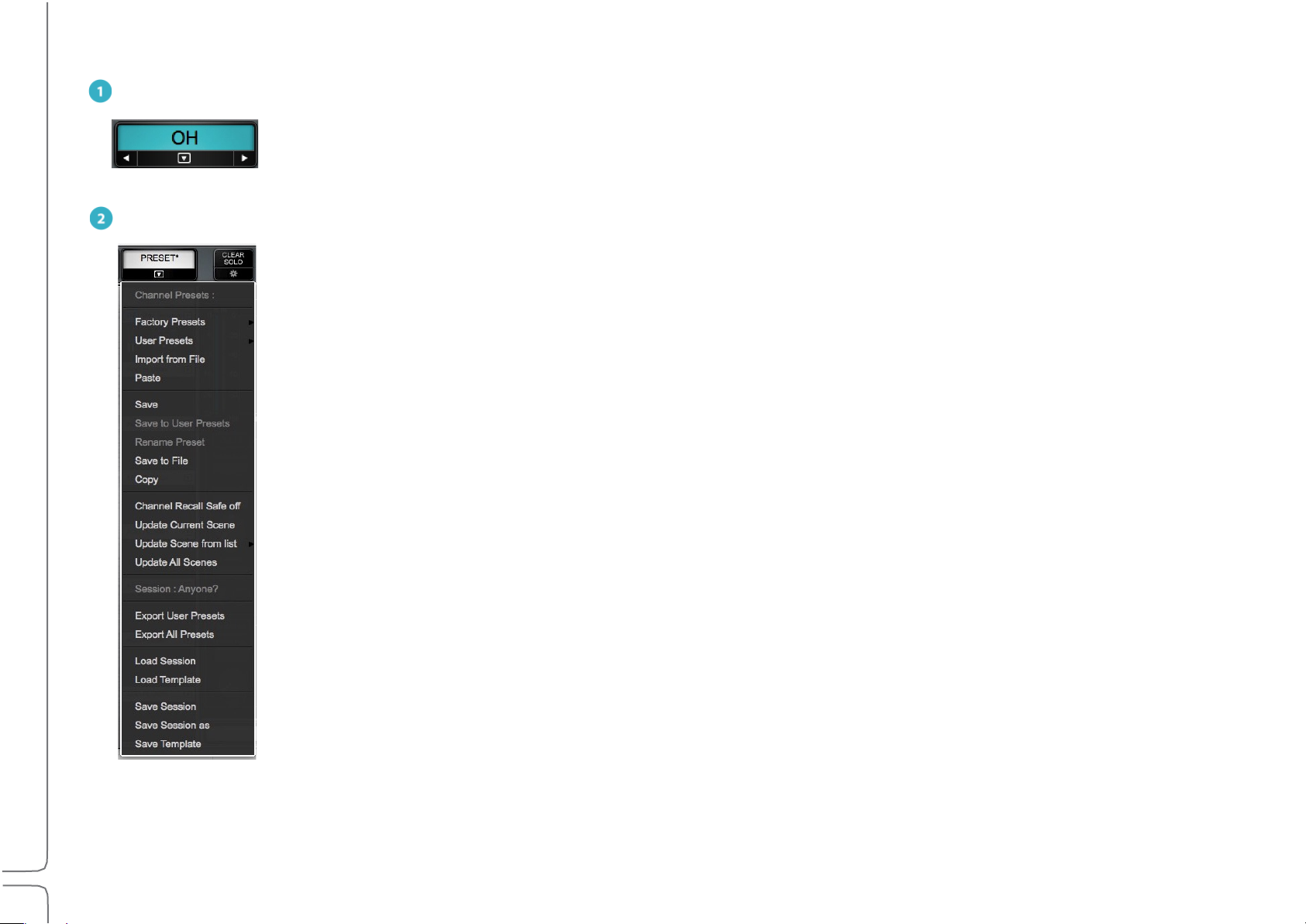
PRESETS MENU
The Presets menu is divided into two sections that serve different purposes.
At the top is the Channel Presets menu section. Channel presets are snapshots of the current condition of the
selected channel. These menu items are used to save, load, export, import, and manage presets. Channel Recall Safe
status is also set here. Presets are saved as part of a session. To use presets from another session, choose the Import
from File menu item. The name of the current channel preset is shown in the Preset box above.
Beneath the Presets section is the Session menu section. It provides quick access to sessions and it enables the
presets for the entire current session to be saved to files.
The Presets menu is always visible from all windows.

12
Waves eMotion LV1 User Guide | Introduction
Factory Presets (load)
A library of presets supplied by Waves. A factory preset cannot be modified. Instead, open it and save as a
user preset.
User Presets (load)
A list of user-defined channel presets, saved from within the current session or imported from another. To
delete a user preset, hold Ctrl before opening the Preset menu. When then opening the User Preset
menu, preset names will be preceded by “Delete.” Select the preset and it will be deleted. This cannot be
undone.
Import from File
Opens a navigation window to locate presets files that have been saved. Imported presets are added to
the User Presets menu.
Paste
Pastes the copied channel condition to another channel. The Copy command copies all rack information.
Paste enables you to choose what channel information will be replaced in the target track.
Save
Saves the channel condition to the loaded channel preset, overwriting it.
Save to User Presets
Creates a new user preset. These are saved as part of the current session. Consider this a “Save As”
function.
Rename Present
Changes the name of the current channel preset.
Save to File
Creates a file that is saved at a user-defined location and can be imported to any session (the extension is
xps). Unlike user presets, these are not embedded in the session.
Copy
Copies the current channel preset. A copied preset can be pasted to any other channel in the current
session. There are several Paste options.
Set Channel Recall Safe
Temporarily excludes all channel parameters from scene changes, even if those parameters are within
the scope of the scene change. A Small “Safe” indicator appears next to the channel name when it is in
Recall Safe mode.
Update Current Scene
Updates the loaded scene with the current mixer condition.

13
Waves eMotion LV1 User Guide | Introduction
Session Menu Section
Export User Presets
Creates a file with all user presets for the entire session, not just those of the selected channel. The
exported presets are stored as one .xps file that can be saved to other media.
Export All Presets
Exports a file that contains the presets—not just the user presets—of all channels in the session.
Load Session
Presents a list of existing sessions. If the current session is not saved, you will be prompted to do so.
Load Session Template
Presents a navigation window for loading a session template. Loading a template does not alter the
current I/O inventory and external patching.
Save Session
Overwrites the loaded session file with the current mixer condition.
Save Session As
Saves the current mixer condition as a new session.
Save Session Template
Saves the current session as a session template.
This menu section is used to manage presets for the entire current session. It is also used to save and load mixer sessions.
Sessions and Templates are discussed in the Show chapter of this User Guide.
14
Waves eMotion LV1 User Guide | Introduction
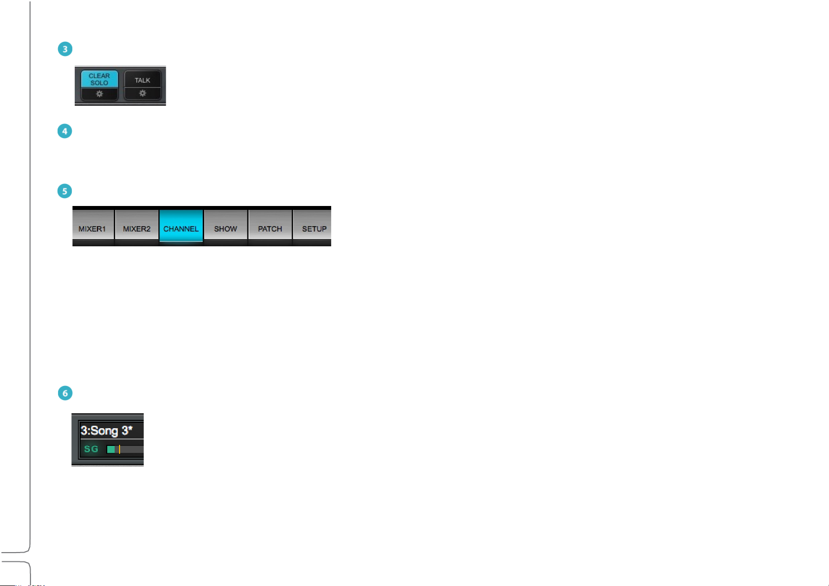
CLEAR SOLO
Mixer 1 and 2
Two multi-mode, multi-layer mixing interfaces.
Channel
A detailed view of a selected channel. A channel’s inputs and outputs, aux sends, and plugin processing can be
controlled here.
Show
A workspace for managing sessions and scenes.
Patch
A patch bay for connections between the mixer and I/Os, within the mixer, and between devices.
Setup
Assigns I/O devices, servers, and controllers. Manages mixer, network, and interface settings.
Clears active solos or cues on all tracks.
Cues and solos are activated on the Mixer window. Configure Cue in the Cue control page, which is accessed with the
Gear button below Clear Solo. Refer to Channel > Cue Section for more about the cue function.
TALK
Activates talkback. Click on the gear button to access the Talkback configuration page. Refer to Channel >Talkback Section for more
about the Talkback function.
WINDOW SELECTION TABS
Radio button tabs that navigate to the six mixer windows.
SG (SOUNDGRID)
Reports the status of the SoundGrid network. A green SG indicates a normal condition. Red indicates an error, such
as a lost connection to the network or a server error. When the SoundGrid network is down, the mixer can still be
used in an offline mode with offline devices assigned in its inventory. Go to Setup > System Inventory to investigate
network problems.
15
Waves eMotion LV1 User Guide | Introduction
DSP
One indicator displays average and peak processing loads. The average value is displayed as a green bar and peak as
an orange line. Red indicates that an audio drop has occurred. This may happen for two reasons:
Processing overload (momentary or constant) Solution: Disable some plugins
Some plugins exhibit a high average/peak ratio. This may cause temporary CPU overloads that result in audio drops. When adding a
large number of these plugins, the peak and average indicators will drift apart. In such cases, some of these plugins may need to be
disabled.
High network usage (channels over the network) Solution: Increase server network buffer size.
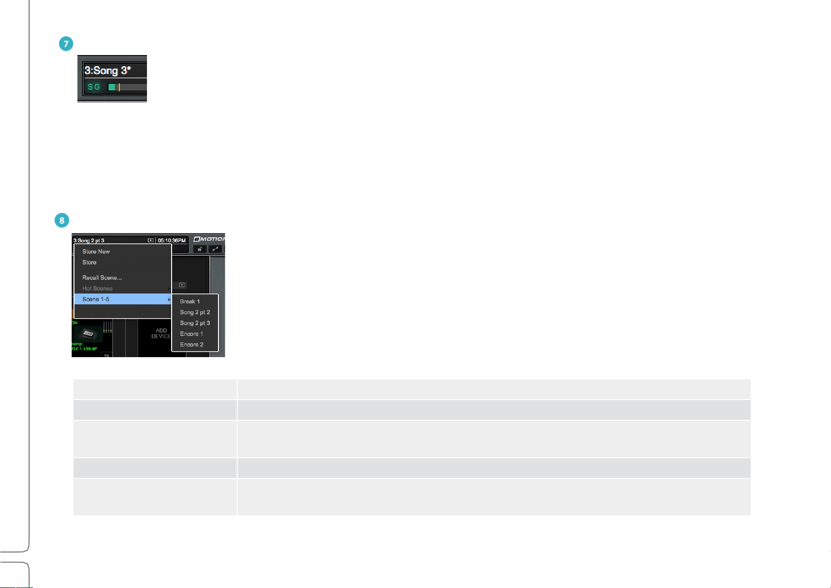
SCENES MENU
The Scenes menu is used to quickly store and recall scenes within the current session. The name of
the current scene is displayed in the box. If a scene has been modified since it was recalled, it is
followed by an asterisk (*). The Scenes menu is available from any window.
Store New Creates a new user-named scene based on current condition.
Store Overwrites the recalled scene with current mixer condition.
Recall Scene
Hot Scenes Provides immediate access to up to eight high-priority “Hot” scene snapshots.
Scene 1–32
(scene select submenu)
Directly recalls a scene based on its place in the scenes list. Type a number and the
corresponding scene will be recalled.
Shows all scenes associated with the session in banks of 32 scenes.
Maximum number of scenes: 1000.

16
Waves eMotion LV1 User Guide | Introduction
MESSAGES
Reports network status. Messages may indicate a sample rate mismatch, a general change in network status, buffer overload, etc.
Troubleshoot network and device issues in the System Inventory page (Setup > System Inventory).
CLOCK
When MIDI control is used, this box can display MIDI time code.
LOCK
Locks/unlocks mixer surface, I/O routing, and/or plugin parameters to prevent unwanted changes during a live event. The scope of
mixer lock is defined in the Setup window (Setup > Mixer Settings > Lock). A password can be assigned to this function.
FULL SCREEN MODE
Fits the mixer window to full-screen view. Click again to return to normal view. Use the recommended resolution of 1280 x 768 for
ideal full-screen display.

17
Waves eMotion LV1 User Guide | Introduction
CHAPTER 1
T
SETUP WINDOW
he Setup window provides the tools to configure the
mixer and determine its behavior.
The window has three pages:
• System Inventory
• Mixer Settings
• U/I Settings
Use the tabs on the left side of the window to choose
between these pages
18
Waves eMotion LV1 User Guide | Chapter 1: Setup Window
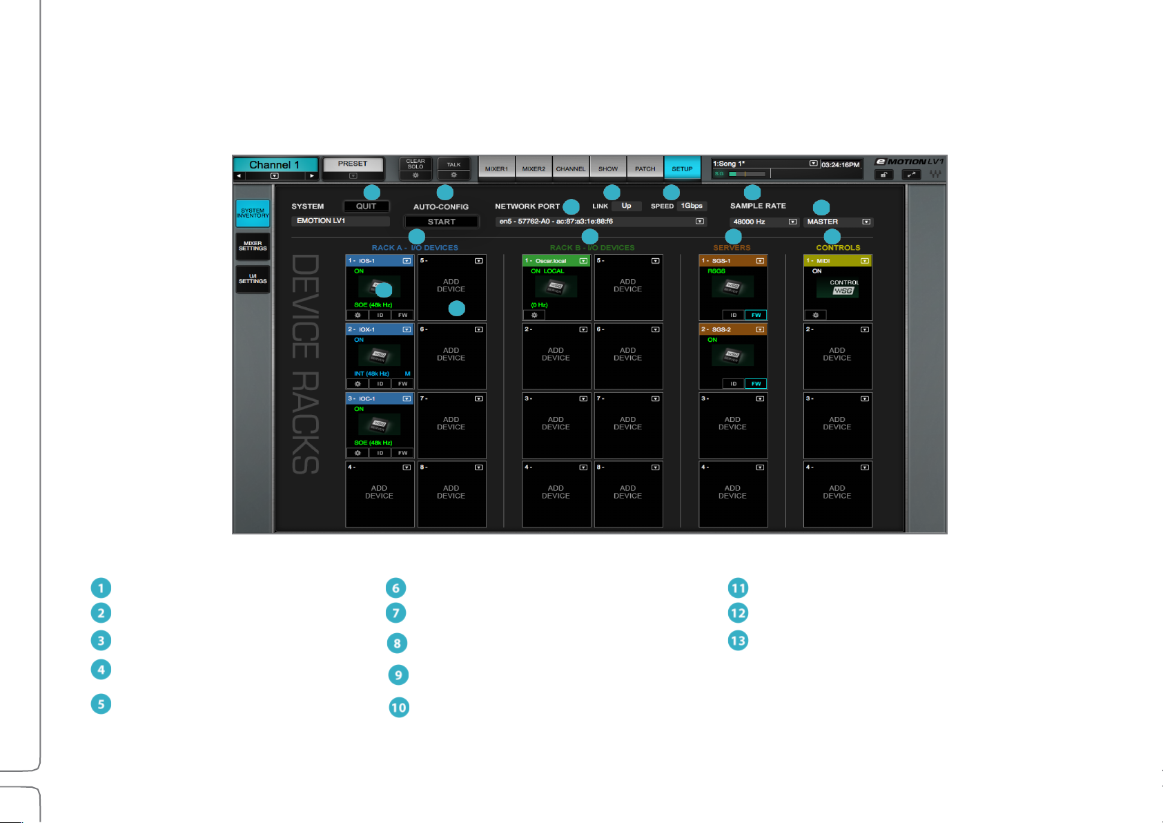
1
Quit application
6
System sample rate
11
Control racks
2
Auto-configure devices
7
Sample rate master/slave selector
Populated rack slot
3
SoundGrid network port selector
8
I/O Racks A (hardware + software I/Os)
Empty rack slot
4
Ethernet link status indicator
I/O Racks B (hardware + software I/Os)
5
Network speed indicator
10
Server Racks
13
12
11
10 9 8
3
6 5 4 2 1
System Inventory Page
The System Inventory page is used to assign and manage I/Os, servers, drivers, and controllers. The top portion of the page deals with
network status. Devices are assigned in the racks below.

19
Waves eMotion LV1 User Guide | Chapter 1: Setup Window
System Inventory Page Displays and Controls
This section describes the controls and menu items of the System Inventory page. It is followed by examples of how to use the System Inventory
page in order to set up the mixer (Setup > Configuring a Basic Mixer Setup).
1. Quit
Closes the session and quits the application. When the mixer is in full-screen mode, use this button to exit the application. When it is not
in full-screen mode, closing the application windows will quit the mixer.
Before quitting, the mixer prompts whether or not to save the current session.
Yes: Save the current mixer condition on the existing file. No: Quit without saving.
NETWORK CONTROLS
2. Auto-Configure / Start
A mixer system can be configured manually or with the aid of an auto-configure tool. This tool inventories all devices in the SoundGrid
network and then sets up a mixer system based on available assets. The resulting session includes device assignment and patching, as
well as mixer configuration. Auto-configure is discussed later in this chapter (Setup > Using the System Inventory Page > Configuring a
Basic Mixer Setup).
3. Network Port
Shows all detected network ports on the host computer. Choose the port that connects to the SoundGrid devices or network switch. We
recommend that this port is used exclusively for SoundGrid devices.
4. Link
Reports the status of the Ethernet connection to the computer running the eMotion LV1 software. Options: UP / DOWN / INVALID
5. Speed
Reports the speed of the SoundGrid network. Options: 100 Mb/sec, 1 Gb/sec, N/A.

20
Waves eMotion LV1 User Guide | Chapter 1: Setup Window
Sample Rate Controls
6. Sample Rate Master/Slave Status Selector
Controls whether the mixer is the sample rate master or a slave. As such, it determines how the sample rate of a system is established.
7. Sample Rate Selector Menu
Sets the system sample rate when the mixer is the sample rate master. The Sample Rate window displays the sample rate of the system.
The menu is disabled when the mixer is a sample rate slave, since it can set the sample rate only when in the master mode.
The sample rate of the clock master device can always be set from its control panel, whether the mixer is in Sample Rate Master or Slave
mode. Sample rate is discussed later in this chapter (Setup > System Inventory > Sample Rate Master vs. Sample Rate Slave).
DEVICE RACKS
8. I/O Rack A
Assign up to eight I/O devices. These can be hardware devices, software I/Os (drivers), or a combination of these.
9. I/O Rack B
Assign up to eight I/O devices. Racks A and B are identical.
10. Servers Rack
Assign up to eight I/O devices per rack. These can be hardware devices, software I/Os (drivers), or a combination of these.
The two racks are identical.
11. Control Protocols Rack
Assign control surface devices.
12. Populated Device Slot
When a device has been assigned to a slot, its icon appears here. The icon contains information about the device.
13. Empty Device Slot
A slot with no assignment is labeled “Add Device.”
21
Waves eMotion LV1 User Guide | Chapter 1: Setup Window
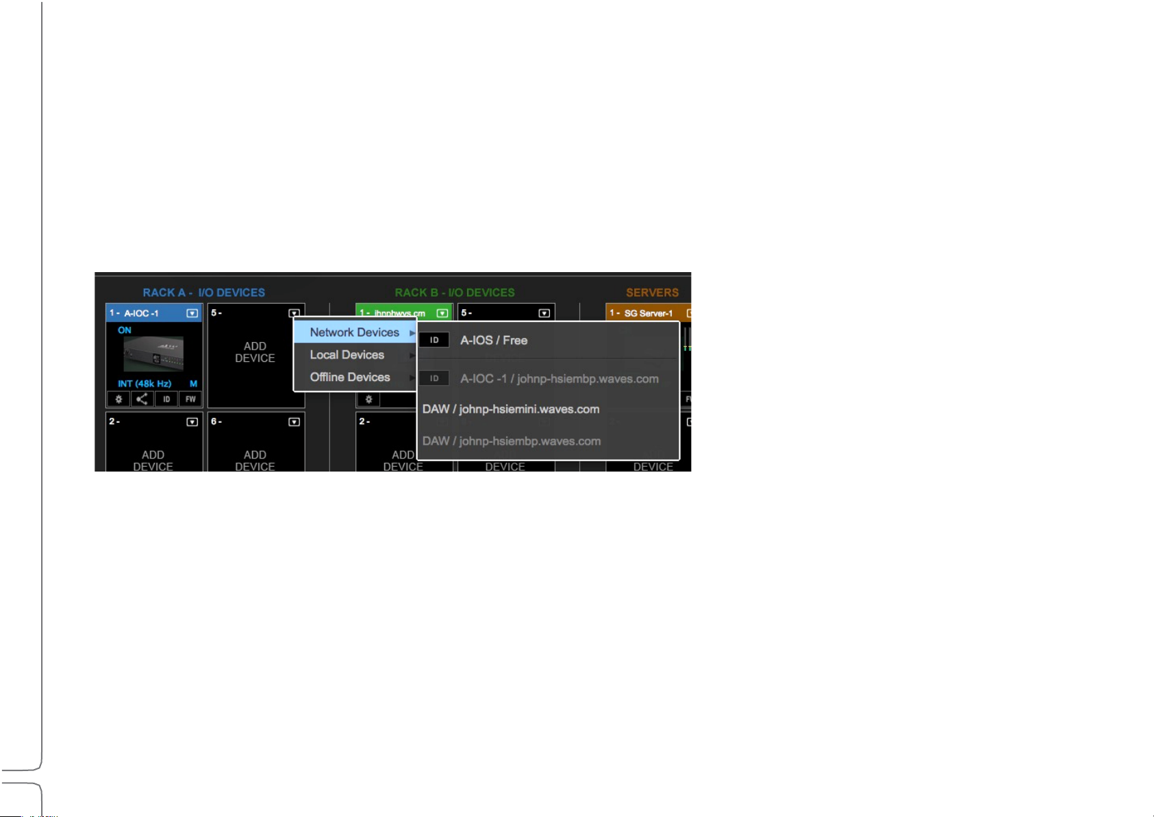
Device Racks: Configuring and Managing Network Devices
Network+
All working devices attached to this SoundGrid SOE network
Local+
The host computer’s drivers
More than one driver can be assigned to an eMotion LV1 system. This provides for a primary driver as well as backups
Offline+
Templates of devices that can be used to create sessions without a server and I/O devices
Device Racks are used to assign and control the hardware and software I/Os, servers, and controllers available on the network. Use these
to set up a new configuration or to modify an auto-configured setup.
Racks A and B—I/O Devices
Racks A and B assign hardware and software I/O devices to the mixer. Racks A and B can be used interchangeably.
A rack consists of eight slots, each of which can hold one I/O device. The arrow in the rack slot opens a drop-down list of devices that are
part of the mixer’s SoundGrid network.
There
are three categories of assignable devices to choose from.
Available devices are shown in black. Devices that are not available for assignment are gray.
The rack slot number determines the device’s place in the Patch window and in certain drop-down menus. Device sequence is not
important, but some engineers choose to use one rack for PA devices and the other for monitoring.
The ID button next to the device name activates a changing-color LED on the device front panel to help identify the physical unit.
22
Waves eMotion LV1 User Guide | Chapter 1: Setup Window
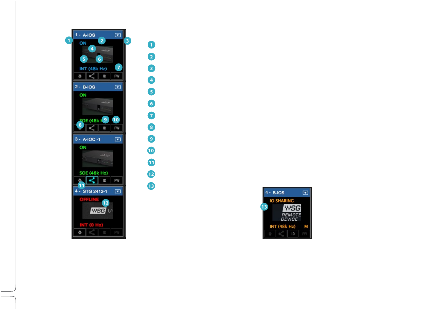
I/O Device Racks Displays and Controls
1
Slot sequence number
2
Device name
3
Device menu access
4
Device status
5
Clock source
6
Sample rate
7
Clock master indicator
8
Device’s control panel button
Identify hardware
Firmware status and re-flash
Enable sharing
11
Offline device
Shared device
There are several status indicators and buttons on the icon itself and just below it. The color of the text in the slot indicates the master/
slave status of the device.
(Blue=Master; Green=Slave; Red=Device not available)
23
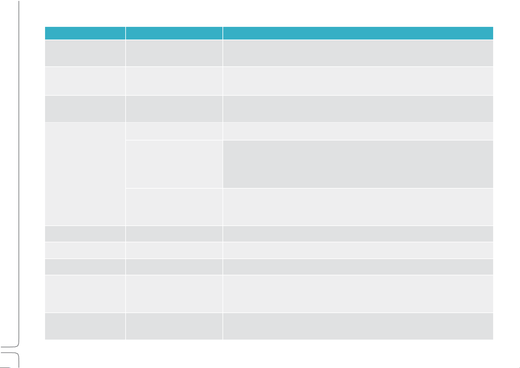
Waves eMotion LV1 User Guide | Chapter 1: Setup Window
Indicator
Possibilities
Function
Slot Sequence
Number
Rack A 1–8; Rack B 9–16
Indicates the rack slot number. I/Os appear in the Patch window in this sequence.
Device Name
Text entry
The device product name followed by a number is the default name. Change
the device name by double-clicking on its Name Box.
Devices Menu
Drop-down menu
Used to add and remove devices from the slot and to set the device as clock
master.
Device Status
On
Device is active.
NA
Device is unavailable. Likely causes:
•Device is assigned to another system.
•Device or firmware is incompatible with current SoundGrid Studio software.
•Device was previously assigned to this user, but is not currently connected.
Offline
A virtual device is assigned to this rack slot for offline preparation of sessions
without I/Os connected. All device patching will be maintained when the session
is launched on a complete system.
Clock Source
INT, SOE, AES, WC, DigiLink
Clock source of this device.
Sample Rate
44.1, 48, 88.2, 96 kHz
Sample rate of device.
Clock master
M (Master) / (blank = slave)
Identifies the device as the clock master of the SOE network.
Control Panel Access
Gear button
Click to access device’s control panel to adjust preamps, configure channels,
and control clock. Refer to the I/O device manufacturer’s user guide for more
information.
ID Hardware
Locate hardware device
Activates lights on the front panel of the hardware device associated with the
icon.
24
Waves eMotion LV1 User Guide | Chapter 1: Setup Window
FW
Status of device’s firmware:
Gray
Firmware is compatible with installed mixer software.
Blue
Firmware is compatible with installed mixer software, but a newer version
exists. Firmware should be updated as soon as possible.
Red
Firmware is not compatible or is out of date. Click the FW button to re-flash
device hardware.
Offline device
Red
Device is offline.
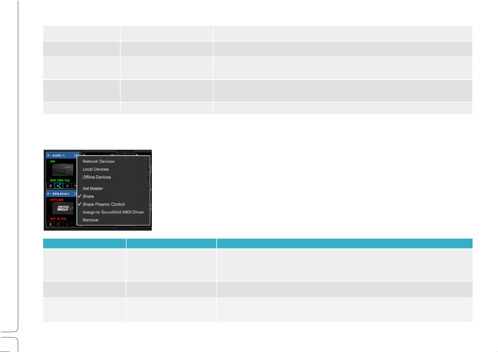
I/O Devices Menu Items
Menu Item
Possibilities
Function
Set Master
A list of all devices that can
be used as a clock source
for the local SOE network.
Designates the device as the SOE network clock master and other devices clock
slaves. The letter “M” and the blue text in the slot indicate that the device is the
master.
Share
Check/Uncheck
Allows sharing of I/O channels on this device with other systems.
Share Preamp Control
Check/Uncheck
Allows remote users to control the preamps of the shared device.
Once an I/O device has been assigned to a rack slot, additional menu items are available.
25
Waves eMotion LV1 User Guide | Chapter 1: Setup Window
Assign to SoundGrid
MIDI Driver
Check/Uncheck
Assigns any MIDI-port-equipped I/O device to the SoundGrid MIDI driver. The
device can then serve as a port for other MIDI devices. The assigned device
appears to MIDI controllers as “SG Device I/O.” Refer to Appendix 2.
Remove
Releases the device from the local host. It will then be available to other
drivers.
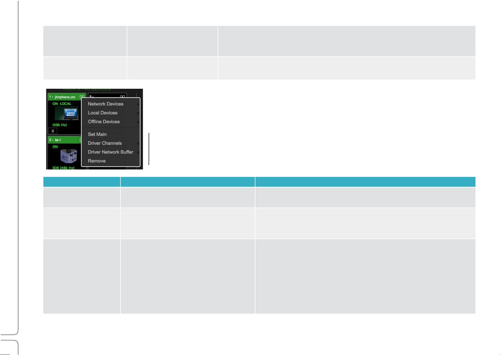
These menu items apply only to drivers.
Menu Item
Possibilities
Function
Set Main Driver
Assigns main driver.
Assigns this as the main driver. The second driver serves as a
backup.
Driver Channels
Range: 32–128 channels
Default: 32 channels
Sets the number of channels assigned to the SoundGrid ASIO/Core
Audio driver. More driver channels can increase network load and
may require more buffering.
Driver Network Buffer
(Values in samples)
Range @ 44.1–48 kHz:
104, 144, 192, 240, 288, 336, 384, 432,
480, 528, 576, 1024
Range @ 88.2–96 kHz:
208, 256, 304, 352, 400, 448, 496, 544,
592, 640, 1088.
The network buffer helps the OS send synchronized information
between the ASIO/Core Audio drivers and the I/Os through
the network port. When many channels are going in/out of the
driver(s) to several destinations, the Driver Network Buffer may
need to be increased to reduce the possibility of audio drops or
artifacts as a result of overloading the network port driver.
All computers on the network should have the same up-to-date versions of eMotion LV1 and SoundGrid Studio software installed. You
can download the latest version from Waves.com.
 Loading...