


 Loading...
Table of Contents |
|
|
Chapter 1 ........................................... |
About the C1 |
.... 5 |
|
The C1 in brief |
............ 5 |
|
C1 Component plug-ins............ |
6 |
|
C1's Setup Library ............ |
6 |
Chapter2 ............................... |
Comp/Exp module......... |
7 |
|
About the compressor/expander ............ |
7 |
|
Controls ............ |
8 |
|
Bypass control ............ |
8 |
|
Level reference control ............ |
8 |
|
Makeup gain ............ |
8 |
|
Threshold............ |
8 |
|
Ratio ............ |
9 |
|
Attack ............ |
9 |
|
Release ............ |
9 |
|
PDR (Program Dependent Release) ............ |
9 |
|
EQ Mode switch ............ |
9 |
|
Gain reduction Meter .......... |
10 |
|
Comp/Exp control level meter .......... |
10 |
Chapter 3 ....................... |
Gate/Expander module....... |
11 |
|
About the Gate/expander .......... |
11 |
|
Gate/expander module controls .......... |
12 |
|
Bypass control .......... |
12 |
|
Gate/expander control .......... |
12 |
|
Floor .......... |
12 |
|
Gate Thresholds.......... |
12 |
|
GateOpen .......... |
12 |
|
GateClose .......... |
12 |
|
Attack .......... |
13 |
|
Release .......... |
13 |
|
Hold .......... |
13 |
|
EQ Mode switch .......... |
13 |
|
Gain reduction Meter .......... |
14 |
|
Gate/expander control level meter .......... |
14 |
|
Linking controls in the two dynamics modules .......... |
14 |
C1 Parametric Compander Plug-In Manual 1

Chapter 4 |
..................................... The filter module .. |
15 |
|
About the filter module ......... |
15 |
|
Filter Controls ......... |
16 |
|
Type ......... |
16 |
|
Frequency ......... |
16 |
|
Q ......... |
16 |
Chapter 5 ............. |
Other controls and I/O metering .. |
17 |
|
Lookahead switch ......... |
17 |
|
About lookahead ......... |
17 |
|
Input/Output Graph ......... |
18 |
|
About the input/output graph ......... |
18 |
|
Indicators and controls ......... |
19 |
|
Comp/Exp display ......... |
19 |
|
Gate/Exp display ......... |
19 |
|
Keying mode ......... |
19 |
|
Key modes ......... |
19 |
|
Monitor switch ......... |
20 |
|
Audio ......... |
21 |
|
Sidechain ......... |
21 |
|
Passive (unprocessed) ......... |
21 |
|
Input and Output Levels ......... |
21 |
Chapter 6 ................................... |
Basics of operation .. |
22 |
|
The Compressor module ......... |
22 |
|
LowRef/PeakRef mode ......... |
24 |
|
Which level reference mode should you use? ......... |
24 |
|
Adjustment of the compressor in LowRef mode ......... |
25 |
|
Adjustment of the compressor in PeakRef mode ......... |
25 |
|
How to adjust PDR ......... |
45 |
Chapter 7 ..................... |
The Gate/Expander module .. |
26 |
|
To use as a Wideband Gate ......... |
26 |
|
To use as a Wideband Expander ......... |
27 |
|
To use the Floor control ......... |
27 |
|
The Filter module ......... |
28 |
Chapter 8 ................................... |
Sidechain Tutorial .. |
29 |
|
Next step ......... |
29 |
|
Another de-esser ......... |
29 |
2 C1 Parametric Compander Plug-In Manual

Chapter 9 ................ |
Intro to Combination setups .. 31 |
|
|
Classic Combinations |
.......... 31 |
|
High-level Compressor + De-Hisser .......... |
31 |
|
Compress + De-reverb.......... |
33 |
Chapter 10............................ |
Setup Library listing .. 35 |
|
|
Simple Setups.......... |
35 |
|
Compression.......... |
35 |
|
Noise Reduction .......... |
35 |
|
De-Essers.......... |
35 |
|
Enhancers.......... |
35 |
|
Keying Setups.......... |
36 |
Chapter 11..... |
Conceptual block diagrams of all EQ mode options ..... |
37 |
|
Key modes.......... |
40 |
Chapter 12................. |
C1 Technical Specifications .. 43 |
|
C1 Parametric Compander Plug-In Manual 3

The control window of the Waves C1 Compressor/Gate
4 C1 Parametric Compander Plug-In Manual

Chapter 1 - About the C1
The Waves C1-Compressor/Gate is a studio-quality stereo dynamics processor and a "parametric compander". The C1 is also a fully featured dynamic filtering processor capable of many unique effects including sound sweetening, enhancement applications, and applications requiring correction of sound quality problems. For maximum flexibility and efficiency, the C1 breaks into smaller components, such as the C1comp and C1gate, or the C1c/sc (comp with sidechain). This lets you choose exactly the dynamic tool needed for the job you have. The C1comp and C1 gate (which don't have sidechain or lookahead) now can be used at 88.2/96kHz on some native platforms.
The C1 is designed for optimal subjective sound. While it is rich in features and functionality, and can do many things unavailable on any other dynamics processor (whether analog or digital) on the market, the design is based on features that sound good to the ear.
The C1 - in brief
The C1 consists of three independent stereo processing modules that can be used together in many different ways:
•Compressor/expander module
•Gate/expander module
•Filter/equalization module
The compressor/expander module (Comp/Exp) is capable of operating as a high-level compressor, a gentle high level expander, or as a mid-level compressor whose compression can be“tuned”at any user-chosen signal level. This module also has a unique cancellation dynamics mode for cancelling out very high-level sounds.
The gate/expander module (Gate/Exp) is capable of operating as a fully-featured expander or gate. It can also be used to take lower level signals and “compress them upwards”.
The filter/equalization module (Filter) has a variety of filtering capabilities for many different kinds of processing, from conventional sidechain dynamics processing to a unique bandsplit dynamic EQ mode. This bandsplit configuration allows compression, expansion, or gating of any desired frequency band.
Each module can be set for different operating modes, plus various combinations can be used for efficient use of your processing power. For example, the Comp/Exp can perform wideband dynamic processing while the Gate/ Exp module gates only the high frequencies (hiss gate). Another example would be using the compressor for bass compression while the Gate/Exp module gates rumble.
C1 Parametric Compander Plug-In Manual 5

C1 Component plug-ins
On most host applications and platforms, you can select just the audio processing you need and use only the power necessary to do the job. The C1 has several plug-in components in the menu, and most have mono and stereo options.
Each has their own separate Factory Presets and User Presets. Information on each of the Factory presets will be in the C1 documents installed onto your hard disk. For more information about Component plug-ins, read the Component chapter in the WaveSystem Manual.
As of this printing, here are the current components; new ones may be added in future updates, and will be noted in the plug-in Read Me file. Some examples for each component are listed.
•C1comp — a wideband compressor/expander, no sidechain; (voice or instrument, individual track compression, gentle soft-knee mastering, 'uncompression' by soft-knee upward expansion, soft-knee limiting)
•C1gate — a wideband gate/downward expander, no sidechain; (track gating, smooth voiceover downward expander, gate hold, low-level compression)
•C1c/sc — compressor with sidechain or split-band compression; (HF limiter, LF limiter, de-esser, de-popper, sidechain drum gate, any-Frequency limiter/compressor/expander, no-pump sidechain mastering compressor)
•C1comp/gate — compressor and gate, wideband, when sidechain is not needed; (voice or instrument, general "outboard" application, track insert)
•+C1c/g — the "full" plug-in, with compressor, gate, sidechain EQ, and IDR; (precision sidechain mastering dynamic tool, multi-band multi-function processor, wideband comp with HF gate, simultaneous compression and upward presence enhancer, any frequency-specific "compress up" tools
•C1c/g — same as +C1c/g, except without IDR.
The Setup Library
For extensive control and fast setups, the C1 system includes an extensive Setup Library. It will take you directly to the essence of the C1.You can also use it as quick starting points in your work and as a tutorial for the features of C1. Waves strongly encourages you to try the Setup Library. A list of all setups in the library is included in Appendix A at the end of this User’s Guide.
Included in this book is the C1 Setup Guide which consists of extensive documentation written by Michael Gerzon, including his highly insightful tips on every aspect of the C1. If the C1 seems a bit daunting, check the Setup Guide for a more application-specific approach.
6 C1 Parametric Compander Plug-In Manual
Chapter 2 - About the compressor/expander
In the menu, you'll have a "C1comp" option, which is the Comp/Exp module by itself, with no sidechain control. The EQ Mode button is omitted when C1comp is used.
The Comp/Exp module is a soft knee variable-ratio processor which at maximum compression becomes a softknee limiter. The softness of the knee has been designed to reduce limiter gain about 3 dB at the limiting threshold.
The dynamic processor is unusual in two respects. First, for moderate compression ratios, the actual dynamic curve compresses over a range to about 20 or 30 dB above threshold, rather than extending the range indefinitely high. As explained below, this is much more flexible than a conventional compressor, while still allowing conventional use when working within 20 or 30 dB above threshold.
Second, an extended ratio control range permits (1) controlled high-level expansion by using ratios of between 0.5:1 and 1:1 and (2) a unique high-level “cancellation” mode beyond limiting, displayed as a negative compression ratio. Very high level signals well above threshold can be nearly cancelled out completely by using these negative ratios.
C1 Parametric Compander Plug-In Manual 7
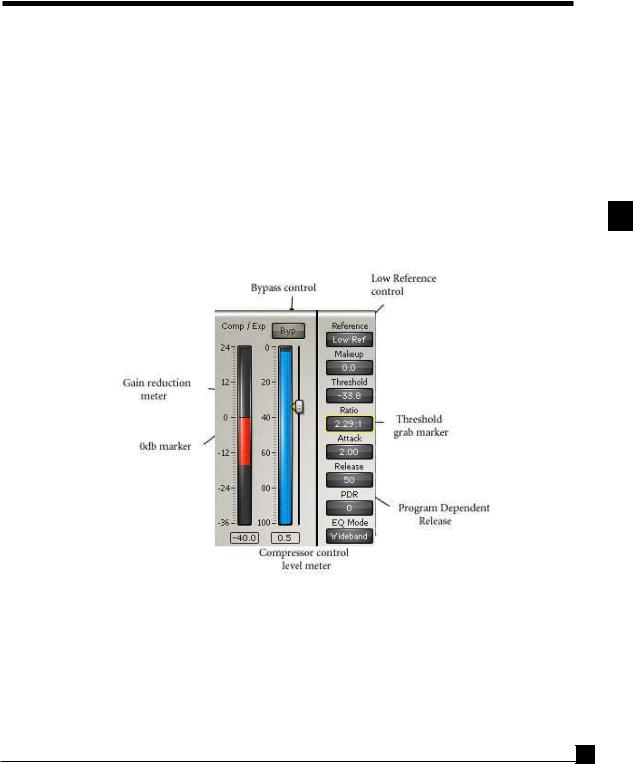
Controls
Bypass control
This switches the module’s processing in and out. Shows Bypass when the module is out.
Level reference control
This has no effect on the sound but affects the output level and how the makeup control works:
LowRef mode [Low-level reference]. This is the conventional mode for compressors, in which the output drops as the threshold is lowered (and more gain reduction occurs).
PeakRef mode [Peak-level reference]. This permits easy adjustment of the Comp/Exp when you want to keep peak levels approximately the same. For example, when in PeakRef mode, as you lower the Comp/Exp threshold, the output gain increases, keeping the output level approximately the same.
Makeup gain
This is the traditional “output” level of the Comp/Exp module and is calibrated in dB, ranging from -40 dB to +40 dB.
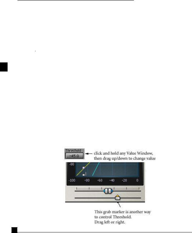
Threshold
Calibrated in dB below 0dBFS (Full Scale digital). This is the input level above which the soft knee compression/ expansion starts acting to a significant degree. Adjust the Threshold by clicking and dragging on this Value Window, by dragging the triangle-shaped grab marker next to the Comp/Exp control level meter, or by dragging the upward-pointing grab marker under the input/output graph. (See illustration on next page.) You can change the Threshold by clicking and dragging on the Value Window, by direct numeric entry, or with the up/down arrow keys.
8 C1 Parametric Compander Plug-In Manual

Ratio
This control adjusts the compression (or expansion) ratio in the region above threshold. A ratio of 1:1 corresponds to no compression, whereas approaching 50:1 corresponds to a soft-knee limiter. Ratios between 0.5:1 and 1:1 give highlevel expansion. Ratios in the control range above 50:1 are shown as negative values between -50:1 and -5:1. This mode is termed “cancellation” mode and is useful for cancelling out unwanted very loud signals while retaining quieter ones. Cancellation mode can result in dynamics that sound very odd, but it does have a number of uses explained later in the manual. You can also change the Ratio by clicking and dragging on the Value Window, by direct numeric entry, or with the up/down arrow keys.
Attack
Calibrated in msec. Adjusts the attack time of the Comp/Exp with time constants from 0.01 msec to 1 second. You can change the Attack by clicking and dragging on the Value Window, by direct numeric entry, or by the up/down arrow keys.
Release
Calibrated in msec. Adjusts the release time of the Comp/Exp with time constants from 1 msec to 10 seconds. You can change the Release by clicking and dragging on the Value Window, by direct numeric entry, or by the up/down arrow keys.
PDR (Program Dependent Release)
This control allows the release time to vary according to program content. When set to the lowest value, release time is fixed at the value shown in the release window.You can change the PDR by clicking and dragging on the Value Window, by direct numeric entry, or by the up/down arrow keys.
At higher settings, release time is shortened for short-duration transients; a slower release is used for longer duration signals.
The PDR calibration in milliseconds is a rough indication of the length of transients below which release time will be shortened. Thus for a PDR of 150ms, transients shorter than about 150ms will have a shortened release time. For transients longer than 150ms, the release time is the one specified by the Release control.
EQ Mode switch
The EQ Mode switch is only available when sidechain is used and therefore is not seen in the "C1comp" component interface.
This has three modes: Wideband, Sidechain and Split.
In Wideband mode, the Comp/Exp operates as a conventional wideband compressor.
In Sidechain mode, the sidechain audio signal used to control the dynamics is first passed through the filters in the EQ module to make the dynamics respond only to a defined frequency band in the audio.
In Split mode, the sidechain audio signal is filtered, but the main signal is also split into two complementary bands: the
C1 Parametric Compander Plug-In Manual 9
active band (whose frequency response is shown in red on the graph) and the passive band (shown in blue on the graph). Only the active band is subjected to the Comp/Exp, and the passive band is not dynamically processed in any way. By this means, a dynamic equalizer, whose action is confined to the active band, is obtained.
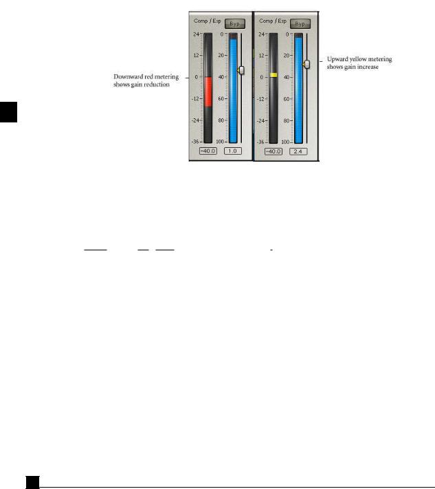
Gain reduction Meter
This shows the instantaneous gain reduction in dB (in red below 0 dB) or gain increase in dB (in yellow above 0 dB) of the Comp/Exp. The meter does not show the effect of makeup gain.
The value window above each meter in C1 shows the largest absolute peak since the last ‘reset’ of the meter. To reset any peak numeric meter, click directly on the peak value itself, or its meter bar.
Note: When in PeakRef mode, the Gain reduction meter will show the actual gain change for the signal. This may be a bit confusing at first. For instance, if you are compressing a signal while in PeakRef mode, the peaks will be kept about the same if Makeup is set to 0.0dB. The Gain meter will show a positive value, indicating the amount of the gain increase necessary to keep the peaks about the same. Conversely, if you are expanding, then the meter will show how much the gain is reduced to keep the peaks about the same.
Comp/Exp control level meter
This blue meter shows the sidechain signal level that controls the Comp/Exp. The meter time constants match the Comp/Exp attack and release times. The threshold can be conveniently adjusted by dragging the small triangle grab marker beside this meter.
10 C1 Parametric Compander Plug-In Manual
Chapter 3 - Gate/Expander module
About the Gate/expander
In the menu, you'll have a "C1gate" option, which is the Comp/Exp module by itself, with no sidechain control. The EQ Mode button is omitted when C1gate is used.
The Gate/Exp processor is operable in two modes: (1) as a soft-knee low-level expander for gentle reduction of low-level signals, or (2) as a gate including hold and hysteresis adjustments for well-behaved gating of low-level signals.
The Gate/Exp has a full range of adjustments which are independent of those in the Comp/Exp module, although, as explained later, some of the controls of the two modules may optionally be linked together for ease and speed of adjustment.
The extended floor control range is unique to this gate/expander. It permits not just a controlled degree of gain reduction below threshold, but even an increase in gain for low-level signals, which can create a low level compression effect when needed. This is the low-level compressor mode. In addition, Negative Floor values (indicated by a capital ‘N’ after the value) are for gate cancellation mode. This is useful in split modes for single-ended dynamic noise reduction, explained later in this manual, and even more extensively in the C1 Setup Guide.
C1 Parametric Compander Plug-In Manual 11

Gate/expander module controls
Bypass control
This switches the module’s processing in and out. Shows Bypass when the module is out.
Gate/expander control
You can switch the mode of the Gate/Exp module to either Gate or Expander.
Floor
Calibrated in dB. Floor adjustment allows some signal to remain in order to avoid a complete signal cutoff. This adjusts the amount of residual signal gain at low levels when the gate is closed or the expander is at large gain reductions. When Floor is set to -infinity dB, essentially no signal is left at low levels. When set to 0 dB, the signal is unchanged at low levels. When set to positive gains, up to 12 dB, the signal level at low levels is actually increased, creating a low-level compression effect whereby quiet signals are increased in level. This low-level compression effect is particularly useful in the soft-knee expander mode.
In expander mode, the Floor control also goes beyond the -infinity setting to negative polarity settings (-100 N to - 10 N). This is indicated by a negative number of dB followed by the letter N to indicate “negative polarity”. This gives the expander a steeper expansion ratio below threshold, and of cancels sounds out completely when they are the indicated number of dB below GateOpen threshold.
Adjust Floor by clicking and dragging on the Value Window, by direct numeric entry, or with the up/down arrow keys.
Gate Thresholds
The two gate thresholds of the C1 allow you to adjust settings to minimize gate “chatter”, the rapid opening and closing of the gate when signals are near the gate threshold.
GateOpen
Calibrated in dB below OdBFS.When in the Gate mode, GateOpen is the input threshold level above which the gate is opened to let the signal through. When in the Expander mode, GateOpen is the level at which soft knee expansion starts acting to a significant degree.
Adjust GateOpen threshold by dragging the upper equilateral triangle marker next to the Gate/Exp processor control level meter, or by dragging the right equilateral triangle marker under the input/output graph. You can also change GateOpen by clicking and dragging on the Value Window, by direct numeric entry, or with the up/down arrow keys.
GateClose
Calibrated in dB below OdBFS. In gate mode, GateClose controls the level below which gate is closed to stop signals from getting through. It is not used in expander mode. GateClose level is always equal to or less than GateOpen level.
12 C1 Parametric Compander Plug-In Manual

Adjust GateClose by dragging the lower equilateral triangle marker next to the Gate/Exp control level meter, or by dragging the left equilateral triangle marker under the input/output graph. You can also change GateClose by clicking and dragging on the Value Window, by direct numeric entry, or with the up/down arrow keys.
Note: In the expander mode of the Gate/Exp module, the GateClose and Hold controls have no effect, and the GateOpen control acts as a threshold control for the point where expansion action begins.
Attack
Calibrated in msec. Adjust the attack time of the expander/gate with time constants from 0.01 msec to 1 second. This adjustment is independent of the Attack time in the Comp/Exp module, although the two can be linked as described below. You can also change Attack by clicking and dragging on the Value Window, by direct numeric entry, or with the up/down arrow keys.
Release
Calibrated in msec.Adjust the release time of the expander/gate with time constants from 1 msec to 10 seconds. This adjustment is independent of the Release time in the Comp/Exp module, although the two can be linked as described below.You can also change Release by clicking and dragging on the Value Window, by direct numeric entry, or with the up/down arrow keys.
Hold
Calibrated in msec. This control adjusts the length of time during which the gate is guaranteed to be held open.
Hold is particularly useful in creative gating applications in order to allow a fixed duration of a gated sound to be heard. It should be set at a low value unless you wish to guarantee a minimum duration of unprocessed transient to be let through. Please note that when the Gate/Exp module is in expander mode, GateClose and Hold controls have no effect.
EQ Mode switch
The EQ Mode switch is only available when sidechain is used and therefore is not seen in the "C1gate" component interface.
This has three modes: Wideband, Sidechain and Split.
In Wideband mode, the Gate/Exp operates as a conventional wideband gate or expander.
In Sidechain mode, the sidechain audio signal used to control the dynamics is first passed through the filters in the EQ module to make the dynamics respond only to a defined frequency band in the audio.
In Split mode, the sidechain audio signal is filtered, but the main signal is also split into two complementary bands: the active band (whose frequency response is shown in red on the graph) and the passive band (shown in blue on the graph). Only the active band is subjected to the Gate/Exp, while the passive band is not dynamically processed in any way. By this means, a dynamic equalizer, whose action is confined to the active band, is obtained.
C1 Parametric Compander Plug-In Manual 13

When using the full C1comp/gate with sidechain, the EQ mode of the Comp/Exp module and the Gate/Exp module may be chosen independently of one another. For example, you can combine a wideband compressor with a high-frequency gate.
Gain reduction Meter
This shows the instantaneous gain reduction in dB (in red below 0 dB) or gain increase in dB (in orange above 0 dB) of the Gate/Exp dynamic processor.
Gate/expander control level meter
This shows the level of the signal controlling the processor (wideband or sidechain EQ). The meter time constants match the Gate/Exp attack and release times. As you adjust the GateOpen level, this meter shows the Peaks of sidechain signal.
Linking controls in the two dynamics modules
Certain controls of the two dynamics modules can be operated simultaneously, for ease of adjustment, by clicking the button between them.
These pairs of controls include:
•Threshold/GateOpen
•Attacks
•Releases
•EQ Mode
For more information on changing multiple controls at the same time, see the WaveSystem Manual.
14 C1 Parametric Compander Plug-In Manual
Loading...