


 MASOSINE PROCESS PUMPS MANUALS
m-maso-sps-gb-04
MasoSine Process Pumps
SPS sinusoidal pumps
Contents
1 |
Declaration of conformity |
2 |
|
13 |
Possible pump orientations |
25 |
||
|
||||||||
2 |
Declaration of incorporation |
2 |
|
|
13.1 |
Changing pump orientation |
25 |
|
3 |
Warranty and liability |
3 |
|
|
13.2 |
Changing rotation direction |
26 |
|
4 |
When you unpack your pump |
4 |
|
14 |
Connecting this product |
|
||
5 |
Information for returning pumps |
5 |
|
|
to a power supply |
27 |
||
6 |
Sinusoidal pumps—an overview |
5 |
|
15 |
Start-up and operation |
27 |
||
7 |
Safety notes |
6 |
|
16 |
Flushing the seal system |
28 |
||
|
7.1 |
Obligation of the operating |
|
|
|
16.1 |
Static flushing device |
28 |
|
|
organisation |
6 |
|
17 |
Cleaning and sterilisation |
29 |
|
|
7.2 |
Organisational measures |
6 |
|
18 |
Heating and cooling option |
31 |
|
|
7.3 |
Obligation of the operators |
7 |
|
19 |
Oil change |
32 |
|
|
7.4 |
Personnel training |
7 |
|
20 |
Troubleshooting |
33 |
|
|
7.5 |
Safety measures |
7 |
|
21 |
SPS 200, SPS 300 and SPS 400: |
||
|
7.6 |
Dangers when handling the |
|
|
|
Adjusting the shaft |
35 |
|
|
|
machine |
7 |
|
|
21.1 |
Adjusting dimension X in |
|
|
7.7 |
Safety measures in normal |
|
|
|
|
models with cast power |
|
|
|
operation |
8 |
|
|
|
frame |
35 |
|
7.8 |
Protective devices |
8 |
|
|
21.2 |
Adjusting dimension X |
|
|
7.9 |
Dangers due to hazardous |
|
|
|
|
in models with stainless |
|
|
|
pumped material |
8 |
|
|
|
steel power frame |
37 |
|
7.10 |
Dangers due to electrical |
|
|
22 |
Dismantling and assembly |
39 |
|
|
|
energy |
8 |
|
|
22.1 |
Dismantling all models |
39 |
|
7.11 |
Dangers due to hydraulic |
|
|
|
22.2 |
Dismantling and |
|
|
|
energy |
9 |
|
|
|
assembling the SPS 100 |
39 |
|
7.12 |
Special danger points |
9 |
|
|
22.2.1 Dismantling the SPS 100 |
39 |
|
|
7.13 |
Constructional changes to |
|
|
|
22.2.2 Assembling the SPS 100 |
47 |
|
|
|
the machine |
9 |
|
|
22.3 |
Dismantling and assembling |
|
|
7.14 |
Noise |
9 |
|
|
|
the SPS 200 |
53 |
|
7.15 |
Limit values for the pump |
10 |
|
|
22.3.1 Dismantling the SPS 200 |
53 |
|
|
7.16 |
Maintenance and repair |
10 |
|
|
22.3.2 Assembling the SPS 200 |
66 |
|
|
7.17 |
Cleaning the pump |
12 |
|
|
22.4 |
Dismantling and assembling |
|
|
7.18 |
Faults |
12 |
|
|
|
the SPS 250, SPS 300, |
|
|
7.19 |
Use as intended |
13 |
|
|
|
SPS 400 and SPS 500 |
79 |
8 |
Safety notes (ATEX) |
13 |
|
|
22.4.1 Dismantling the SPS 300 |
|
||
|
8.1 |
Safety signs |
13 |
|
|
|
and SPS 400 |
79 |
|
8.2 |
Earthing the pump |
14 |
|
|
22.4.2 Assembling the SPS 250, |
|
|
|
8.3 |
Material properties |
14 |
|
|
SPS 300, SPS 400 and SPS 500 |
88 |
|
|
8.4 |
Pressure conditions |
14 |
|
23 |
The static flushing device |
96 |
|
|
8.5 |
Maintenance and repair |
14 |
|
24 |
Tightening torques |
102 |
|
|
8.6 |
Cleaning the pump |
15 |
|
25 |
Parts lists |
104 |
|
|
8.7 |
Medium to be pumped |
15 |
|
|
25.1 |
Pumps |
105 |
|
8.8 |
Coupling |
15 |
|
|
25.2 |
Seals |
123 |
|
8.9 |
Drive |
15 |
|
|
25.3 |
Front support versions |
133 |
9 |
Pump specifications |
15 |
|
|
25.4 |
The flushing ring for tubing138 |
||
|
9.1 |
Dimensions (in millimetres) 16 |
|
|
25.5 The static flushing device |
139 |
||
10 |
Transport |
22 |
|
26 |
Decontamination certificate |
142 |
||
11 |
Installation |
22 |
|
27 |
Trademarks |
143 |
||
12 |
Connection to the piping |
23 |
|
28 |
Publication history |
143 |
||
|
12.1 |
Cavitation |
24 |
|
|
|
|
|
MasoSine SPS sinusoidal pumps User Manual |
|
|
|
|
|
1 |
||

1 Declaration of conformity
This pump complies with: Machinery Directive 2006/42/EC.
2 Declaration of incorporation
When this pump unit is to be installed into a machine or is to be assembled with other machines for installations, it must not be put into service until the relevant machinery has been declared in conformity with the Machinery Directive 2006/42/ EC. See 9 Pump specifications.
Responsible person: Ulrich Fromm, General Manager, MasoSine, Postfach 100, 74358 Ilsfeld, Germany.
Telephone: +49 (0)7062 95600. Fax: +49 (0)7062 64593.
The information in this user guide is believed to be correct at the time of publication. However, MasoSine Process Pumps accepts no liability for errors or omissions. MasoSine Process Pumps has a policy of continuous product improvement, and reserves the right to alter specifications without notice. This manual is intended for use only with the pump it was issued with. Earlier or later models may differ. The most up-to-date manuals appear on the MasoSine website: http://www.masosine.de
MasoSine SPS sinusoidal pumps User Manual |
2 |
3 Warranty and liability
MasoSine warrants, subject to the conditions and exceptions below, through either MasoSine, its subsidiaries, or its authorised distributors, to repair or replace free of charge the pump housing or the pump front cover if it fails within 20 years of the day of manufacture of the product. MasoSine warrants, subject to the conditions and exceptions below, through either MasoSine, its subsidiaries, or its authorised distributors, to repair or replace free of charge any other part of the product which fails within three years of the day of manufacture of the product. Such failure must have occurred because of defect in material or workmanship and not as a result of operation of the product other than in normal operation as defined in this manual.
MasoSine will not be liable for any loss, damage, or expense directly or indirectly related to or arising out of the use of its products, including damage or injury caused to other products, machinery, buildings, or property, and MasoSine will not be liable for consequential damages, including, without limitation, lost profits, loss of time, inconvenience, loss of product being pumped, and loss of production. This warranty does not obligate MasoSine to bear any costs of removal, installation, transportation, or other charges which may arise in connection with a warranty claim.
Specific exceptions to the above warranty are:
Exceptions
Warranty and liability claims for personal and material damage are excluded if they are attributable to one or several of the following causes:
•Use of the machine not as intended
•Incorrect installation, operation or maintenance of the machine
•Operating the machine with defective safety devices or safety and protective devices not correctly attached or not functioning
•Non-compliance with the operating instructions regarding transport, storage, installation, start-up, operation, maintenance and setting of the machine.
•Unauthorised constructional changes to the machine
•Insufficient monitoring of machine parts subject to wear
•Incorrectly performed repairs
•Catastrophe due to the effect of foreign bodies and acts of God
MasoSine grants no implicit warranties on the suitability of the products described for a certain application. Watson-Marlow MasoSine accepts no liability for errors contained in this documentation or consequential damage occurring due to the design, performance and the use of this documentation.
MasoSine’s “General sales and delivery conditions” contain full details. These are available to the purchaser at the latest when the purchase contract is finalised.
MasoSine SPS sinusoidal pumps User Manual |
3 |

4 When you unpack your pump
Unpack all parts carefully, retaining the packaging until you are sure all components are present and in good order. Check against the components supplied lists, below.
Packaging disposal
Dispose of packaging materials safely, and in accordance with regulations in your region.
Inspection
Check that all components are present. Inspect components for damage in transit. If anything is missing or damaged, contact your distributor immediately.
Components supplied (SPS 100, SPS 200, SPS 250, SPS 300, SPS 400 and SPS 500)
•SPS 100, SPS 200, SPS 300 or SPS 400 sinusoidal pump, bare-shaft, with stainless steel or cast iron power frame
•The technical datasheet identifying, describing and defining the pump
•Operating instructions
Optional items
•Coupling
•Coupling guard
•Drive
•Baseplate
Optional special design
•Flush systems
•Guard Master
•Jacketing for heating and cooling
|
stainless |
|
cast iron |
|
power frame |
|
power frame |
|
|
|
|
SPS 100 |
|
|
n/a |
|
|
|
|
|
|
|
|
SPS 200
SPS 250 |
n/a |
|
SPS 300
SPS 400
SPS 500 |
|
|
n/a |
|
|
|
|
MasoSine SPS sinusoidal pumps User Manual |
4 |
Storage
This product has an extended shelf life. However, plastic parts and elastomeric parts should be stored in a cool, dry environment. The blue polyamide gate should be stored in cool, clean water if it will be out of use for more than four weeks. Care should be taken after storage to ensure that all parts function correctly.
5 Information for returning pumps
Equipment which has been contaminated with, or exposed to, body fluids, toxic chemicals or any other substance hazardous to health must be decontaminated before it is returned to MasoSine or its distributor.
A certificate included at the rear of these operating instructions, or signed statement, must be attached to the outside of the shipping carton. This certificate is required even if the pump is unused. See 28 Decontamination certificate.
If the pump has been used, the fluids that have been in contact with the pump and the cleaning procedure must be specified along with a statement that the equipment has been decontaminated.
If a returned pump requires cleaning, a charge will be made. Internal parts that have not been decontaminated will be replaced and a charge will be made.
6 Sinusoidal pumps—an overview
The functioning principle of MasoSine pumps is ingeniously simple.
The pump consists of modular components.
The sinusoidal rotor creates a chamber within the pump body four times per revolution, in which the pumped fluid is displaced. As a filled chamber rotates, it contracts, closes and discharges its contents. At the same time, the opposite chamber opens by the same fraction of a millimetre to draw in more fluid. The result is a pump free of pulsation.
The gate works as a seal between the pressure side and the suction side of the pump. It prevents an equalization of the pressure created by the rotor, stopping it escaping to the suction side.
MasoSine SPS sinusoidal pumps User Manual |
5 |

7 Safety notes
Knowledge of these safety instructions and of the safety regulations in your area is a requirement for safe handling and trouble-free operation of this machine.
These operating instructions contain the most important instructions to operate the machine safely. These operating instructions, especially the safety instructions, must be observed by all persons who work on the machine. In addition, the rules and regulations for accident prevention applicable at the place of use must be obeyed.
The following safety instructions must be observed absolutely. They are an essential and indispensable part of the user documentation. Non-compliance can result in failure of warranty claims.
It is recommended in the interests of all involved to enter all installation measures, maintenance, fault and repair cases, training courses, instructions and special occurrences in a logbook assigned to the machine.
This symbol highlights a safety instruction which must be followed to avoid danger to people or to the pump.
This symbol means: Beware of high voltage.
7.1 Obligation of the operating organisation
The operating organisation must ensure that people who work on the machine are familiar with and comply with the regulations concerning working safety and accident prevention.
7.2 Organisational measures
The personal protective equipment required must be provided by the operating organisation. Safety devices must be checked regularly.
MasoSine SPS sinusoidal pumps User Manual |
6 |
7.3 Obligation of the operators
People who work on the machine must observe the relevant safety regulations concerning working safety and accident prevention before starting work; must read the safety chapter and the warning notes in these operating instructions.
7.4 Personnel training
Only trained people may work on the machine. Their responsibilities must be defined clearly for assembly, start-up, operation, setting, maintenance and repairing.
7.5 Safety measures
The operating instructions must be kept with the machine. General and local regulations for accident prevention and environmental protection, and the operating instructions, must be observed. Safety and danger warnings on the machine must be legible.
7.6 Dangers when handling the machine
The MasoSine pump is built according to state-of-the-art principles and the recognised safety engineering rules. Nevertheless, danger to life and limb of the user or third persons, or impairments to the machine or to other assets, can arise in its use.
The machine must be used only:
•for its intended use
•if it is in a safe engineering condition.
Faults which can impede safety must be rectified immediately.
MasoSine SPS sinusoidal pumps User Manual |
7 |

7.7 Safety measures in normal operation
Operate the machine only if all protective devices are functioning. Before switching the machine on make sure that no one can be endangered when the machine starts. At least once per shift inspect the machine for damage and for proper functioning of the safety devices.
7.8 Protective devices
All protective devices must be attached correctly and functioning before every startup. Protective devices may be removed only after the machine has stopped and protection measures against restarting the machine have been taken.
After spare parts have been fitted, protective devices must be attached according to the operating organisation’s regulations.
If contact with hot or cold machine parts could be dangerous, protection must be provided for the pump user.
7.9 Dangers due to hazardous pumped material
If hazardous material is to be pumped, the appropriate regulations must be observed.
7.10 Dangers due to electrical energy
Work on the electrical supply must be performed only by an electrician.
Check the electrical equipment of the machine regularly. Rectify loose connections and scorched cables immediately.
Keep the control cabinet locked closed or secured with a tool. Access is allowed only to authorised personnel.
If work on parts conducting voltage must be done, call in a second person to switch off the mains power if necessary.
Electrical connection of the pump must be made according to local regulations, by skilled personnel only.
MasoSine SPS sinusoidal pumps User Manual |
8 |
7.11 Dangers due to hydraulic energy
Only personnel with special knowledge and experience in hydraulics may work on hydraulic devices.
Relieve the pressure in the system sections and pressure lines to be opened before starting repair work.
Replace hydraulic hose lines at appropriate intervals, even if no safety-relevant defects are detectable.
7.12 Special danger points
The pump contains a rotating rotor, |
7 |
which can crush or sever fingers and |
|
hands. The pump must be guarded so |
|
that it is not possible for people to hold the |
|
pump by its inlet or delivery ports with the |
|
rotor running. When the rotor is stationary, |
the drive must be secured against unintentional start-up. Increased danger exists if pipes are dismantled or the pump is open.
7.13 Constructional changes to the machine
Make no changes, attachments or conversions to the machine without the manufacturer’s approval. All conversion measures require the written confirmation of Watson-Marlow MasoSine.
Replace machine parts which are not in perfect condition immediately. Use only original spare and wearing parts. Parts not obtained from MasoSine are not guaranteed to be designed and manufactured in compliance with load and safety requirements.
The warranty is invalid if genuine spare parts from MasoSine are not used.
7.14 Noise
The continuous sound pressure level proceeding from the machine should not exceed 70 dB(A). Higher sound pressure levels that can cause deafness can arise, depending upon local conditions. If this occurs, protect the operating personnel with appropriate protective equipment / protective measures.
MasoSine SPS sinusoidal pumps User Manual |
9 |

7.15 Limit values for the pump
The pump’s maximum speed, maximum pressure and maximum temperature are included in the technical data sheet supplied with each pump. These limit values must not be exceeded in any circumstances. This applies in particular when using a frequency converter.
If pump is supplied without a drive, the following values apply:
|
SPS 100 |
SPS 200 |
SPS 250 |
SPS 300 |
SPS 400 |
SPS 500 |
|
Maximum |
10 bar |
10 bar |
15 bar |
15 bar |
15 bar |
15 bar |
|
pressure * |
|||||||
|
|
|
|
|
|
||
Maximum |
1,000 rpm 1,000 rpm 800 rpm |
600 rpm |
600 rpm |
600 rpm |
|||
speed * |
|||||||
|
|
|
|
|
|
||
Maximum |
100°C |
100°C |
100°C |
100°C |
100°C |
100°C |
|
temperature * |
|||||||
|
|
|
|
|
|
||
Ambient |
-12°C to |
-12°C to |
-12°C to |
-12°C to |
-12°C to |
-12°C to |
|
temperature |
+40°C |
+40°C |
+40°C |
+40°C |
+40°C |
+40°C |
|
* These limits may be lower, depending on the drive, the application and the rating of the pump. (See your purchase order confirmation, or contact MasoSine and give your pump’s serial number.) On customer request, higher pressures are possible.
7.16 Maintenance and repair
Inform operating personnel before starting maintenance and repair work. Protect all plant parts and operating media connected before and after the machine, such as compressed air and hydraulics, against unintentional start-up. In all maintenance, inspection and repair work, switch the machine off and secure the main switch against unintentional start-up.
Secure larger assemblies carefully to lifting gear. Check loosened screw connections for firm seating. Use only original spare parts.
After maintenance work is finished, check the safety devices for function.
MasoSine SPS sinusoidal pumps User Manual |
10 |
Bearings maintenance
•The bearings of SPS 100 pumps must be renewed after running for the periods shown in the table below.
|
200 rpm |
400 rpm |
600 rpm |
800 rpm |
1,000 rpm |
5 bar |
10,000 hours |
10,000 hours |
6,986 hours |
5,239 hours |
4,191 hours |
10 bar |
2,079 hours |
1,040 hours |
693 hours |
520 hours |
416 hours |
•We recommend renewing the bearings of SPS 200 pumps with cast iron power frames after running for 10,000 hours at any pressure.
•We recommend renewing the bearings of SPS 200 pumps with stainless steel power frames after running for the periods shown in the table below.
|
200 rpm |
400 rpm |
600 rpm |
1,000 rpm |
5 bar |
10,000 hours |
10,000 hours |
10,000 hours |
10,000 hours |
10 bar |
10,000 hours |
10,000 hours |
10,000 hours |
6,260 hours |
•We recommend renewing the bearings of SPS 250 pumps with stainless steel power frames after running for the periods shown in the table below.
|
200 rpm |
400 rpm |
600 rpm |
800 rpm |
5 bar |
10,000 hours |
10,000 hours |
10,000 hours |
10,000 hours |
10 bar |
10,000 hours |
10,000 hours |
10,000 hours |
10,000 hours |
15 bar |
10,000 hours |
10,000 hours |
10,000 hours |
10,000 hours |
•We recommend renewing the bearings of SPS 300 pumps with cast iron or stainless steel power frames after running for 10,000 hours at any pressure.
•We recommend renewing the bearings of SPS 400 pumps’ with cast iron power frames after running for the periods shown in the table below.
|
200 rpm |
400 rpm |
600 rpm |
5 bar |
10,000 hours |
10,000 hours |
10,000 hours |
10 bar |
10,000 hours |
10,000 hours |
10,000 hours |
15 bar |
10,000 hours |
7 ,689 hours |
5,126 hours |
•We recommend renewing the bearings of SPS 400 pumps with stainless steel power frames after running for the periods shown in the table below.
|
200 rpm |
400 rpm |
600 rpm |
5 bar |
10,000 hours |
10,000 hours |
10,000 hours |
10 bar |
10,000 hours |
10,000 hours |
10,000 hours |
15 bar |
10,000 hours |
7,210 hours |
4,800 hours |
•We recommend renewing the bearings of SPS 500 pumps with stainless steel power frames after running for the periods shown in the table below.
|
200 rpm |
400 rpm |
600 rpm |
5 bar |
10,000 hours |
10,000 hours |
10,000 hours |
10 bar |
10,000 hours |
10,000 hours |
10,000 hours |
15 bar |
10,000 hours |
10,000 hours |
7,500 hours |
MasoSine SPS sinusoidal pumps User Manual |
11 |
Note: Remove the bearing housing of SPS 200, SPS 300 and SPS 400 models only to replace or adjust the shim ring (see 21 Adjusting the shaft). Do not attempt to dismantle the power end of the pump or replace the bearings. Pumps needing repair, servicing, new bearings or other work on the power end must be returned to MasoSine for attention. Special training is available for users of SPS 200, SPS 300 and SPS 400 models. Please contact MasoSine for further information.
7.17 Cleaning the pump
Handle substances and materials used correctly, especially when working on lubricating systems and when cleaning with solvents. For information on cleaning the parts in contact with the pumped fluid, see 17 Cleaning.
7.18 Faults
If an operating fault occurs, switch off the machine and secure it against unintentional start-up.
MasoSine SPS sinusoidal pumps User Manual |
12 |

7.19 Use as intended
The intended use of this product is listed in the order confirmation. The product should not be put to a different use or a use going beyond the use described.
Consult MasoSine if you wish to change the product, its pressure, speed or operating temperature.
8 Safety notes (ATEX)
If your MasoSine pump is to be used in production machinery in potentially explosive atmospheres, it will be equipped accordingly from the factory.
8.1 Safety signs
|
|
|
|
|
|
II 2 G c T4 |
II 2 D c T = 120C |
|
|
|
|
|
|
|
|
Grounding symbol |
|
|
|
|
|
|
|
|
|
|
|
|
|
|
|
|
|
|
|
|
|
|
|
|
|
|
|
|
|
|
|
|
|
|
|
|
|
|
|
|
|
|
|
|
|
|
|
|
|
|
|
|
|
|
|
Pump classification
MasoSine pumps are designed for continuous duty and are therefore assigned to the Device Group II – Application field “dust – or gas – explosive areas”.
Zone classification
MasoSine pumps can be used in explosive areas of zone 1 / 21. This corresponds to the category 2 G / D.
 It is expressly forbidden to use the pumps in zone 0.
Classification of explosive atmospheres
A distinction is made between dust and gas explosive atmospheres. In the model code, the atmosphere is abbreviated with G (Gas) and D (Dust). MasoSine pumps are designed to be used in explosive atmospheres G (Gas) and D (Dust).
Ignition protection
MasoSine pumps pumps are subject to ignition protection “c” constructive safety, according to the standard for non-electric appliances for use in explosion-risk areas, EN 13463-5.
Temperature classes
•EX II 2 G c T4 ≥ 135C
•EX II 2 D c T = 120C
MasoSine SPS sinusoidal pumps User Manual |
13 |
8.2 Earthing the pump
SPS pumps are equipped with an earthing point.
The pump must be earthed by an earthing cable secured to the correct position. SPS 100 must be earthed at the base of the rear foot. Other models must be earthed as shown: with cast iron power frame, right; with stainless steel power frame, below right. This is particularly important in potentially explosive atmospheres.
In addition to earthing the pump, the drive motor must also be earthed. If the drive is not earthed,
the pump unit may not be operated.
8.3 Material properties
The plastic parts fitted inside the pump react more to temperature changes than stainless steel parts. For this reason, the specified maximum fluid temperature for which the pump is designed must not be exceeded. This temperature is included in your purchase documents. If the specified temperature is exceeded, linear expansion may block the pump; this in turn could cause the pump to fail or could result in damage to parts of the pump. In addition, excessive temperatures can accelerate the wear of dynamic parts and reduce the life of plastic parts.
Corrosion may occur to a pump’s cast iron power frame if the paintwork is damaged. Corrosion represents a hazard for the use of pumps in potentially explosive atmospheres (for measures, see 20 Troubleshooting).
Pumps with a stainless steel power frame are not subject to power frame corrosion.
8.4 Pressure conditions
A pressure controller must be installed to avoid over-pressure in the pump as a result of a closed pressure line.
8.5 Maintenance and repair
•Fill the pump with product before starting only outside the explosive atmosphere area. All tools used should comply with ATEX regulations.
•The pump unit must be kept free of dust with a damp cloth: accumulated dust can smoulder.
•The flushing channels in the power frame must be free of blockages and, if necessary, cleaned.
MasoSine SPS sinusoidal pumps User Manual |
14 |
8.6 Cleaning the pump
No solvent cleaning agents may be used to clean the pump as they could create an uncontrollable explosive atmosphere.
8.7 Medium to be pumped
Carbon disulphide and chemicals that are combustible below 120C must not be pumped.
8.8 Coupling
If the pump is used in potentially explosive atmospheres, it must be coupled to the drive by means of an elastic, positive coupling with ATEX certification for use with the pump. Chains, toothed belts, V-belts or similar equipment which may transmit radial forces to the bearings should not be used.
8.9 Drive
Any reduction gears in the drive chain and control units must be ATEX-certified for use with the pump. Combustion engines must never be used.
An inverter must be installed away from potentially explosive atmospheres, or have the same ATEX certification as the pump. In any case the inverter must have the properties required for operation in potentially explosive atmospheres: temperature monitoring, speed limitation, etc.
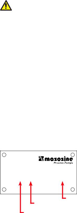
9 Pump specifications
Your pump carries a type plate on the bearing housing. It includes a serial number, which identifies the features of the product. The serial number also appears on the technical data sheet.
MasoSine Process Pumps, 74360 Ilsfeld, Germany
s/n. |
133777 0807 |
Typ |
SPS 200 |
model
month / year of manufacture (eg August 2007)
serial number
MasoSine SPS sinusoidal pumps User Manual |
15 |
Standards
|
2006/42/EC: EC Machinery Directive |
Relevant EC |
73/23/EEC: EC Low Voltage Directive |
directives |
2004/108/EC: EMC Directives |
|
|
|
97/23/EG: Pressure Equipment Directive |
|
Safety of machinery—electrical equipment of machines: |
|
EN 60204-1 |
|
EN ISO 12100, 1-2 : Safety of machinery |
EC |
For ATEX: EN 1127-1: Explosive atmospheres— |
harmonised |
Explosion prevention and protection Part 1 |
standards |
For ATEX: EN 13463-1: Non-electrical equipment |
|
|
|
for use in potentially explosive atmospheres Part 1 |
|
For ATEX: EN 13463-5: Non-electrical equipment |
|
for use in potentially explosive atmospheres Part 5 |
|
EN 809: Pumps and pump units for liquids— |
|
Common safety requirements |
National techni- |
DIN 31000/A1: General principles for the safe design of |
technical products (Amendment 1) |
|
cal standards, |
DIN 11850: Pipes made of stainless steel for food and |
guidelines and |
|
specifications |
chemical industries |
|
DIN 11851: Stainless steel fittings for the food and chemical |
|
industry - Screw pipe connections for expanding and welding |
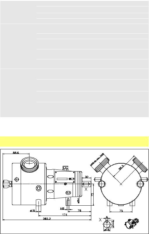
9.1 Dimensions (in millimetres)
SPS 100
MasoSine SPS sinusoidal pumps User Manual |
16 |
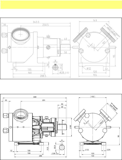
SPS 200 pumps, dimensions
Cast iron power frame
Stainless steel power frame
All critical dimensions of old and new power frame designs are the same, including mounting bolt holes. Both designs are interchangeable
MasoSine SPS sinusoidal pumps User Manual |
17 |
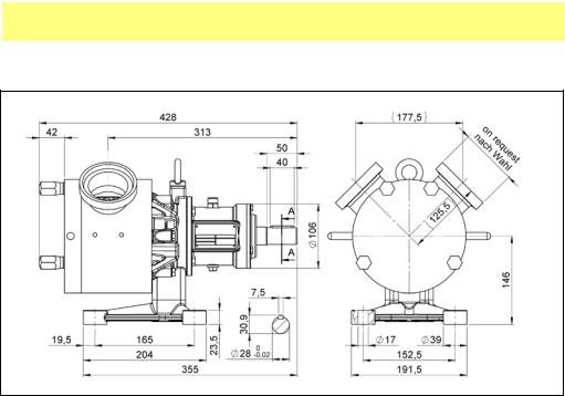
SPS 250 pumps, dimensions
Stainless steel power frame
MasoSine SPS sinusoidal pumps User Manual |
18 |
SPS 300 pumps, dimensions
Cast iron power frame
Stainless steel power frame
All critical dimensions of old and new power frame designs are the same, including mounting bolt holes. Both designs are interchangeable
MasoSine SPS sinusoidal pumps User Manual |
19 |

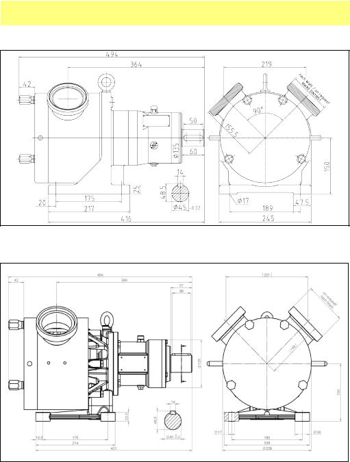
SPS 400 pumps, dimensions
Cast iron power frame
Stainless steel power frame
All critical dimensions of old and new power frame designs are the same, including mounting bolt holes. Both designs are interchangeable
MasoSine SPS sinusoidal pumps User Manual |
20 |
SPS 500 pumps, dimensions
Stainless steel power frame
Unit weights
|
Pump weight, |
Pump weight, |
|
|
||
|
stainless steel |
Weight of standard baseplate |
||||
|
cast power frame |
|||||
|
power frame |
|
|
|||
|
|
|
|
|
||
SPS 100 |
|
|
17.00kg |
37lb 8oz |
Part no: KK-... 13.00kg |
28lb 11oz |
SPS 200 |
23.00kg |
50lb 11oz |
20.00kg |
44lb 1oz |
Part no: KK-... 13.00kg |
28lb 11oz |
SPS 250 |
|
|
39.00kg 86lb |
Part no: KK-... 13.00kg |
28lb 11oz |
|
SPS 300 |
80.00kg |
176lb 6oz |
68.00kg |
149lb 15oz |
Part no: KM-... 19.00kg |
41lb 14oz |
SPS 400 |
160.00kg |
352lb 12oz 125.00kg |
275lb 9oz |
Part no: KG-... 31.00kg |
68lb 5oz |
|
SPS 500 |
|
|
171.00kg 377lb |
Part no: KG-... 31.00kg |
68lb 5oz |
|
MasoSine SPS sinusoidal pumps User Manual |
21 |
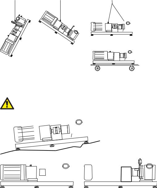
10 Transport
Choose the means of transport according to the size of the pump and the drive. The pump must be suspended correctly for transport. If using a crane or a fork-lift truck, the ropes or belts must be sufficiently dimensioned. If the pump is transported with a lift truck or a fork-lift truck, note that the unit’s centre point is not necessarily the centre of gravity.
7
 7
7


 3
3


 3
3


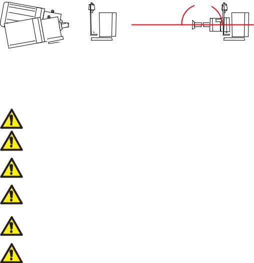
11 Installation
The motor shaft and pump shaft connection must be guarded to protect the user from contact.
 7
7


 7
7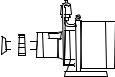


 3
3


•Place the pump on a level surface.
•Do not start the pump without a guard to protect the user from contact.
•The mounting surface should be strong enough to support the pump.
•There should be sufficient space for maintenance work around the pump.
•The motor must receive an adequate air supply.
•If the pump is used in potentially explosive atmospheres, an Ex-protected motor must be used. Contact the manufacturers for assistance.
•The unit must be protected against static charge.
MasoSine SPS sinusoidal pumps User Manual |
22 |
180°
 7
7


 3
3


• Align the pump shaft with the drive shaft.
12 Connection to the piping
Before connection, clean the piping and remove foreign bodies such as welding residues.
Fit elastic intermediate members (compensators) between pump and fixed piping on the suction and pressure sides, to stop pump vibrations being transmitted to the piping system.
Avoid forces and torques acting from the piping on the pump connections (e.g. distortion, expansion due to temperatures etc.).
The piping on the pressure side of the pump should run upwards from the pump, so that residual liquid can flow back into the pump when pumping stops, and total dry running is avoided. Fluid left in the pump facilitates suction when pumping re-starts.
The user must ensure that a pressure rise above the pressure agreed in the purchase order and listed in the technical data sheet is not possible.
MasoSine pumps normally run with such a low resonant frequency that no damage results. However, particularly when running with inverters, certain frequencies can cause interference vibrations which must be avoided. It is important during commissioning to ascertain whether such vibrations exist
and to define them, so that the inverter can be programmed to avoid these frequencies. Similarly, interference from cavitation or rigid lines must be avoided. See 12.1
Cavitation.
MasoSine SPS sinusoidal pumps User Manual |
23 |

12.1 Cavitation
Cavitation is a problem in certain devices where fluid interacts with a moving surface. It can occasionally occur in sinusoidal pumps.
Where a surface moves through a fluid, low pressure areas are formed on the surface. The faster the surface moves, the lower the pressure around it can become. If the static pressure of the liquid falls below its vapour pressure, vapour bubbles form on the pressure side. These implode, causing very high, short-term pressure peaks up to several thousand bar. These pressure peaks can cause material erosion and are noisy.
To identify cavitation
If the pump is very noisy and vibrates vigorously, along with the pipe system attached to the pump, cavitation is likely to be the cause.
To avoid or remove cavitation
Increasing the inlet pressure on the suction side, installing a larger diameter or shorter inlet pipe or slowing the pump may solve the problem. Make sure that the pump is not starved of duty fluid at all times.
Cavitation can destroy the pump. The operator must ensure that the pump can work free of cavitation.
MasoSine SPS sinusoidal pumps User Manual |
24 |
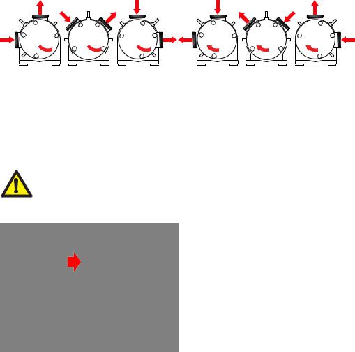
13 Possible pump orientations
The pump can be positioned in three orientations, and rotate clockwise or counterclockwise.
|
|
|
|
|
|
|
|
|
|
|
|
|
|
|
|
|
|
|
|
|
|
|
|
|
|
|
|
|
|
|
|
|
|
|
|
|
|
|
|
|
|
|
|
|
|
|
|
|
|
|
|
|
|
|
|
|
|
|
|
|
|
|
|
|
|
|
|
|
|
|
|
|
|
|
|
9-12 |
10-2 |
12-3 |
|
12-9 |
2-10 |
3-12 |
||||||||||||
Counter-clockwise rotation |
|
|
Clockwise rotation |
|
|
|
|
|
||||||||||
|
of the rotor and motor |
|
of the rotor and motor |
|||||||||||||||
Unless ordered otherwise, the pump is delivered in position 2-10. Special customised nozzle orientations are possible.
13.1 Changing the pump orientation
Disconnect the pump from the mains power, and secure it against unintentional start-up.
SPS 100
• Turn the pump on to its side to allow access to the baseplate securing bolts.
• Remove the three bolts and washers using a 13mm spanner. As each bolt is withdrawn, a spacer between the baseplate and the pump will fall out.
• Three sets of threaded fixing points are provided on the pump; the central set (pictured in use above) allows the inlet and outlet ports to be positioned
at 10-2 or 2-10; the other sets (one fixing point arrowed) allow the pump to be
positioned with the inlet or outlet horizontal and the other port vertical.
•Pass the bolts with washers through the baseplate and the spacers (Note: the longer bolt and the longer spacer secure the baseplate to the bearing
housing at the rear of the pump). Screw the bolts into the set of fixing points appropriate for the desired pump orientation. Tighten to 25Nm using a 13mm spanner.
SPS 200, SPS 250 SPS 300, SPS 400, SPS 500
•Follow the dismantling and assembly steps for your pump model. See 22
Dismantling and assembly
•Remove the screws on the power frame. Turn the housing by an angle of 45° to the left or right.
•Refit the screws in their new position and tighten them to the correct torque:
SPS 200: 16 Nm SPS 250: 16 Nm SPS 300: 33 Nm SPS 400: 56 Nm SPS 500: 56 Nm
Note: If the direction of flow is also changed, the gate and gate guide must be reversed. See 13.2 Changing rotation direction.
MasoSine SPS sinusoidal pumps User Manual |
25 |

Take care that fluid in the pressure line leaves the pump in an upward direction, so that when pumping stops, some fluid remains in the pump. This will make it easier for the pump to draw in viscous products when pumping restarts. This applies particularly when the pressure connection is horizontal: positions 12-3 and 12-9. Take care that the pressure line is run so that the pump rotor is always covered with fluid, and dry running is avoided.
13.2 Changing rotation direction
When the direction of rotor rotation is reversed, the suction side and the pressure side of the pump are exchanged. The orientation of the gate and the gate guide must be changed, too, or the pump cannot pump efficiently. The pump can run for only a short time with the gate and the gate guide wrongly oriented, and it will not achieve more than 2 bar pressure. See 22 Dismantling and assembly.
SPS 100 is shown here. All models are similar.
The gate and gate guide shown inverted to make clear the gate’s position within the guide for counter-clockwise rotor rotation
The gate and gate guide oriented for clockwise rotor rotation
The gate and gate guide oriented for counter-clockwise rotor rotation
If the direction of rotation is reversed, change the rotation direction indicator arrows and mark the suction and pressure ports correspondingly.
Disconnect the pump from the mains power, and secure it against unintentional start-up. Ensure that the direction change is carried out by a trained engineer.
•Follow the dismantling and assembly steps for your pump model. See 22
Dismantling and assembly
•Take special note of the instructions for fitting the rotor, the gate and the gate guide
Take care that fluid in the pressure line leaves the pump in an upward direction, so that when pumping stops, some fluid remains in the pump. This will make it easier for the pump to draw in viscous products when pumping restarts. This applies particularly when the pressure connection is horizontal: positions 12-3 and 12-9. Take care that the pressure line is run so that the pump rotor is always covered with fluid, and dry running is avoided.
MasoSine SPS sinusoidal pumps User Manual |
26 |
14 Connecting this product to a power supply
The motor must be connected according to local regulations by a qualified person. See the instruction manual supplied with your drive motor.
15 Start-up and operation
•If you are starting the pump for the first time, or have performed cleaning or repair work, check first that all screws are correctly and completely tightened.
•The pump may have been contaminated during transport. Remove the pump front cover and clean if necessary before start-up.
•Before you start the pump, check that the gate and the gate guide are in the correct orientation in relation to the suction side and the pressure side of the pump. (See 13.2 Changing rotation direction).
Observe the appropriate regulations if hazardous fluid is to be pumped.
Ensure that the pump is installed in an appropriate position with all necessary safety guards and precautions (sensors, switches, pressure gauges, etc).
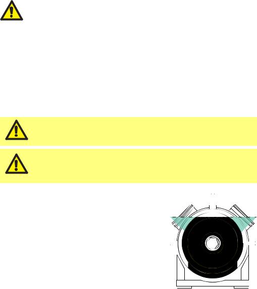
MasoSine pumps must be primed before use. Fluid Before commissioning and during operation, the level
pump must be filled with fluid, with the fluid level above the rotor (see diagram). This can be done
manually through a side channel of your system’s pipework, or by using a vacuum device where very
viscous fluids are to be pumped; contact MasoSine for further information. The need to prime can
be avoided by leaving product in the pump after it is stopped; by leaving CIP or SIP fluid in the pump after cleaning. For ATEX use, fill the pump
away from potentially explosive atmosphere, and be aware that if the pump runs dry, the temperature limit for the explosive area may be
exceeded.
MasoSine SPS sinusoidal pumps User Manual |
27 |
Make sure before start-up that all valves on the pressure and suction sides are open. The pump must not pump against a closed valve without an over pressure valve.
If the pump leaks, stop pumping as quickly as possible and replace the damaged sealing elements. See 22
Dismantling and assembly and 25.2 Seals.
The operator must ensure that the pump can work free of cavitation. Cavitation can destroy the pump. See 12.1 Cavitation.
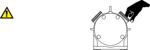
16 Flushing the seal system
Flushing fluid at atmospheric pressure—usually water—flushes the area behind the seal system and prevents the product from hardening and damaging the seal system. If a static flushing device is fitted, the flushing fluid fills the area behind the seal.
•Cast iron power frame: If no static flushing device is fitted, adapt a fitting and a tube to the threads of the intake and outlet in the power frame (see diagram below; models differ) and circulate flushing fluid through the system.
•Stainless steel power frame: Make sure that the correct flush ring is installed with tube connections and circulate flushing fluid through the system.
•The flushing medium must be at least suitable to the product being pumped. It should not contain abrasive particles, which would damage the seals. We recommend that transparent plastic tubes are used as flushing tubes.
•The pump should be flushed without pressure: the flushing fluid should be allowed to drain from the system without pressure.
•Fill the pump with liquid to prevent it from running dry, possibly via a separate intake valve connected to the suction or pressure pipe.
•If your pump is set up for permanent flushing, always check the intake and outlet (see diagram below).
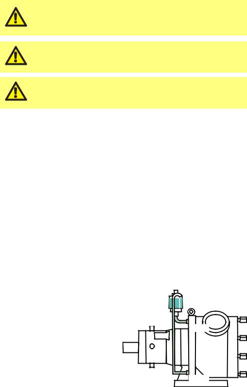
16.1 Static flushing device
|
|
|
Intake |
Before |
commissioning, |
fill |
the |
flushing device (if supplied) with a suit- |
|||
able flushing fluid, depending on the |
|||
product |
being pumped. Fill the sight glass |
||
with flushing fluid until the fluid level is
just below the bend in the outlet pipe.
Outlet
Note: The diagram shows a flushing
device fitted to a pump with a cast iron frame. Pumps with stainless steel frames are similar.
MasoSine SPS sinusoidal pumps User Manual |
28 |

17 Cleaning and sterilisation
MasoSine SPS pumps may be cleaned in place. Please follow our CIP cleaning instructions—see below.
Maintaining a clean process line is vital to maintain a high level of hygiene and no contamination of an end-product. Contamination costs time and money.
The heat or chemical reaction from clean-in-place (CIP) and steam-in-place (SIP) cleaning processes damages a living cell’s essential structures, including the cytoplasmic membrane, rendering the cell no longer viable.
The process automatically re-circulates cleaning detergent and rinse solutions .
The benefits of clean-in-place (CIP) and steam-in-place (SIP)
•Cleaning is faster
•Cleaning is less labour-intensive
•Cleaning is repeatable
•There is a reduced chance of operators being exposed to hazardous chemicals
Clean-in-place (CIP) for MasoSine products
Clean-in-place (CIP) is a method of cleaning the interior surfaces of pipes, vessels, process equipment and associated fittings without disassembling .
The CIP procedure
•Before the CIP process begins, a preliminary clean should be performed at maximum speed with no back pressure. This will remove most of the residual product.
•Suitable cleaning fluids for the CIP process may include concentrations below 1% of additives. They may be:
• Sodium hydroxide in distilled water • Nitric acid in distilled water
• Phosphoric acid in distilled water
•CIP cleaning can be carried out between 80°C and 90°C as standard.
•Cleaning should be done at maximum pump speed to achieve a good cleaning result.
•It is very important that the differential pressure on the discharge side of the pump is at least 3.0 bar / 43.5 psi higher than the pressure on the suction side of the pump during the CIP process.
Attention: Keep a minimum distance of 50cm from the pump while performing high-pressure cleaning.
MasoSine SPS sinusoidal pumps User Manual |
29 |

•A choke valve should be installed in the discharge pipeline immediately after the pump. Close the choke valve slowly until the pressure difference is correct .
•The CIP time for the pump is in accordance with the time required for system cleaning: usually 20-40 minutes.
flow of |
|
|
|
|
|
|
cleaning |
|
X |
|
Y |
|
|
fluid |
|
|
|
|
||
|
|
bar/psi |
|
bar/psi |
|
choke |
|
|
|
|
|
|
|
|
suction |
|
discharge |
valve |
||
|
side |
|
side |
|
||
Y-X ≥
3 bar / 43.5 psi
Steam-in-place (SIP) for MasoSine products
Steam sterilisation kills micro-organisms through the application of moist heat (saturated steam) under pressure without disassembly.
•Sterilising the pump with standard equipment is possible up to 120°C only at standstill.
•The pressure should be high enough to ensure that the steam reaches all parts of the static pump through the existing clearances.
Class II SIP and CIP |
Maximum |
Recommended |
procedure |
temperature |
pressure differential |
|
|
|
CIP |
80-90°C / 176-194°F |
3 bar |
|
|
|
SIP |
120°C / 248°F |
- |
|
|
|
Key CIP and SIP safety information
•A distance of one metre around the pump should be kept clear during SIP to minimise danger in case of leakage.
•CIP and SIP processes should be monitored continuously.
•If a leak occurs during CIP or SIP, the pumphead should not be touched until system pressure has been relieved and the pumphead has been allowed to cool down.
•Ensure that an acclimatisation period is observed after SIP before the pump process is started. The temperature inside a standard pump should not exceed 85C (176F) during operation.
MasoSine SPS sinusoidal pumps User Manual |
30 |
 Loading...