


User’s Manual
MC100
MC100
Pump Control Module
User’s Manual
(Profibus DP)
MC100 Users Manual Profibus DP - rev 4 |
Rev. 3 |
Page 1 of 40 |
|
|
|

|
|
|
Users Manual |
|
|
|
MC100 |
CONTENTS: |
|
|
|
1 |
Introduction............................................................................................................................. |
|
4 |
1.1 |
Terms used in this manual ...................................................................................................... |
|
4 |
1.2 |
Precautions............................................................................................................................. |
|
4 |
2 |
General description of MC100 ................................................................................................ |
|
5 |
2.1 |
Overview................................................................................................................................. |
|
5 |
2.2 |
Introduction & design purpose ................................................................................................ |
|
5 |
2.2.1 |
How it works / Technical description of operation.................................................................... |
5 |
|
2.3 |
Flexicon pumps used in multi-filling system, short description................................................. |
6 |
|
2.4 |
How to operate the dispenser pumps...................................................................................... |
7 |
|
2.5 |
Communication on the Profibus .............................................................................................. |
|
7 |
3 |
Technical specifications .......................................................................................................... |
|
8 |
3.1 |
Dimensions............................................................................................................................. |
|
8 |
3.2 |
Specifications ......................................................................................................................... |
|
9 |
3.3 |
Unpacking and inspection of MC100 |
..................................................................................... |
10 |
3.3.1 |
Identifying the module........................................................................................................... |
|
10 |
3.3.2 |
Identifying the parts .............................................................................................................. |
|
11 |
3.4 |
Mounting............................................................................................................................... |
|
11 |
3.4.1 |
Choosing a place to mount the MC100 ................................................................................. |
11 |
|
4 |
Wiring ................................................................................................................................... |
|
12 |
5 |
Fieldbus network node address and front plate indicators..................................................... |
14 |
|
5.1 |
Network node address switches S1/S2: ................................................................................ |
14 |
|
5.2 |
P1/P2 LED indicators:........................................................................................................... |
|
14 |
5.3 |
Display P4/P5 ....................................................................................................................... |
|
15 |
5.3.1 |
Start up states....................................................................................................................... |
|
15 |
5.3.2 |
Network address................................................................................................................... |
|
15 |
5.3.3 |
Alarmand warning display................................................................................................... |
|
15 |
5.3.4 |
Dipswitch .............................................................................................................................. |
|
15 |
6 |
Configuring the fieldbus network to the MC100..................................................................... |
16 |
|
6.1 |
Connecting the MC100 and the pumps for the first time........................................................ |
16 |
|
6.2 |
Configuring to the Profibus DP network ................................................................................ |
16 |
|
7 |
Operating the MC100............................................................................................................ |
|
17 |
7.1 |
Process Data Exchange (Cyclic data)................................................................................... |
17 |
|
7.1.1 |
Structure of the data package sent to and received from the MC100 |
.................................... 17 |
|
7.1.2 |
Process control bits – word 0 (PLC MC100) ..................................................................... |
20 |
|
7.1.3 |
Process status bits (MC100 PLC) |
..................................................................................... |
22 |
7.1.4 |
Process control bits for the pumps– word 1 to 9 (PLC MC100)......................................... |
23 |
|
7.1.5 |
Process status bits from the pumps – word 1 to 9 (MC100 PLC)...................................... |
24 |
|
7.2 |
Operation Parameters/Parameter specifications ................................................................... |
25 |
|
7.2.1 |
List of basic parameters........................................................................................................ |
|
25 |
7.2.2 |
Control Data Word - data word 10 (PLC MC100).............................................................. |
27 |
|
7.2.3 |
Status words from parameters transfer (MC100 PLC) ...................................................... |
28 |
|
7.2.4 |
Data word 11 ........................................................................................................................ |
|
28 |
7.2.5 |
Alarm and warning (MC100 PLC) |
..................................................................................... |
28 |
7.3 |
Examples:............................................................................................................................. |
|
29 |
7.3.1 |
New speed to pump 1: .......................................................................................................... |
|
29 |
7.3.2 |
New calibration value to pump 3: .......................................................................................... |
|
30 |
8 |
Alarm and warnings .............................................................................................................. |
|
32 |
8.1 |
Alarms handling .................................................................................................................... |
|
32 |
8.1.1 |
Module alarms ...................................................................................................................... |
|
32 |
8.1.2 |
Pump alarms ........................................................................................................................ |
|
32 |
8.2 |
Warnings handling ................................................................................................................ |
|
33 |
MC100 Users Manual Profibus DP - rev 4 |
Rev. 4 |
Page 2 of 40 |
|

|
|
Users Manual |
|
|
MC100 |
8.2.1 |
Warnings .............................................................................................................................. |
33 |
9 |
Trouble shooting ................................................................................................................... |
34 |
9.1 |
Trouble-shooting................................................................................................................... |
34 |
9.2 |
Opening the MC100 for service/replacement of PCB’s ......................................................... |
35 |
10 |
Decommissioning ................................................................................................................. |
36 |
10.1 |
Advice about dismantling / removal / disposal....................................................................... |
36 |
10.2 |
Environmental conditions / -regulations................................................................................. |
36 |
10.3 |
The WEEE system................................................................................................................ |
36 |
11 |
Appendix 1............................................................................................................................ |
37 |
12 |
Appendix 2............................................................................................................................ |
38 |
12.1 |
Tube tables........................................................................................................................... |
38 |
12.2 |
Volume, Speed and acceleration .......................................................................................... |
39 |
12.2.1 |
PD12 .................................................................................................................................... |
39 |
12.2.2 |
PD22 .................................................................................................................................... |
39 |
12.2.3 |
GD30 .................................................................................................................................... |
39 |
13 |
Declaration of Conformity ..................................................................................................... |
40 |
MC100 Users Manual Profibus DP - rev 4 |
Rev. 4 |
Page 3 of 40 |
|
|
|

Users Manual
MC100
1 Introduction
1.1 Terms used in this manual
Fieldbus |
DeviceNet, Profibus. |
Fieldbus interface module |
Anybus Compact Com Module from HMS Industrial Networks AB |
Filling system |
a MC100 and up to 16 pumps |
Pump |
Any Watson-Marlow Flexicon pump communicating on FlexNet (PDxx, |
|
GDxx, DDxx) |
WMF |
Watson-Marlow Flexicon |
1.2 Precautions
This manual should be read thoroughly before using the MC100.
It is strongly advised that no wiring is connected or disconnected on the MC100 while power supply is turned ON
MC100 Users Manual Profibus DP - rev 4 |
Rev. 4 |
Page 4 of 40 |
|
|
|
Users Manual
MC100
2 General description of MC100
2.1 Overview
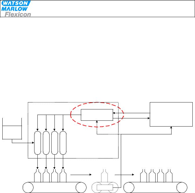
MC100 is a pump control module for controlling up to 16 WMF Pumps. The basic function is
•to receive filling data from the filling line control system through an industrial fieldbus
•based on data received from the filling line control system to calculate operating values for the pumps
•to transmit data to the pumps connected to the MC 100 via FlexNet
•to receive data from the pumps connected to the MC 100 via FlexNet
•to transmit the pump data to the filling line control system
MC100 constitutes together with WMF pumps a filling system designed for incorporation into a larger filling line as described below.
|
Filling system |
|
|
||
|
|
|
|
Recipe |
Filling line control system |
|
|
|
|
Commands |
|
|
|
|
|
incl. storing of recipe and |
|
|
|
|
MC100 |
|
|
|
|
|
|
|
HMI |
|
|
|
|
Actual |
|
|
|
|
|
parameter |
|
|
|
|
|
Status |
|
Product |
|
|
|
|
|
Pump |
Pump |
Pump |
Pump |
|
|
|
|
|
|
Achieved |
|
|
|
|
|
fill amount |
|
|
|
|
Scale |
|
|
2.2 Introduction & design purpose
The MC100 is a small module for mounting inside the control cabinet of the filling line.
It is designed with the purpose of integrating Watson-Marlow Flexicon pumps into a filling line.
2.2.1 How it works / Technical description of operation
Via the fieldbus the MC100 receives operating data from and sending data to the control system for the filling line. The data are divided in three types:
•General data for the pump system
•Set-up data for each pump
•Operation data for each pump
The MC100 sets up the pump system according to the data received from the control system for the filling line.
All control and status signals for the individual pumps connected to the MC100 are sent to the MC100 via the fieldbus. The dispensing can also be controlled via hardwired signals. Please see the manual for the pumps for more details regarding the hardwired signals.
MC100 Users Manual Profibus DP - rev 4 |
Rev. 4 |
Page 5 of 40 |
|
|
|

Users Manual
MC100
The MC100 cannot store data such as recipes and historical data. These data must be stores in the control system for the filling line and be transmitted to the pump system when needed.
2.3 Flexicon pumps used in multi-filling system, short description.
The Watson Marlow Flexicon multi filling system consists of up to 16 filling dispensers (pumps) connected via a fieldbus to a MC controller.
The dispensers can be peristaltic dispenser pumps (PD12 and PD22) and gear dispenser pumps (GD30).
The MC controller can be either a MC12 controller with integrated keyboard and display to enter data and control the dispensing or MC100 for integration in control systems.
This manual describes the MC100 controller.
The pumps are used for dispensing accurate doses of liquid into vials.
For this purpose there are a number of parameters, which are used to control the pump:
Speed: |
The range for the dispensing speed is 30 to 600 rpm depending on the pump |
|
and the tube selected |
Acceleration: |
The range is 1 to 200 rpm/s depending on the pump and the tube selected. |
Reverse (back sucking): Is a figure between 1 and 10 defining a short reverse pumping to prevent
|
dripping after the dispensing. |
Tube: |
The pumps hold a tube table of up to 10 tubes, which can be read from the |
|
pumps. The tubes are depending on the pump type. Thus the pump table |
|
can be down loaded from the pump software via the MC100. |
Volume: |
The volume the pump has to dispense at each filling. Please also see serial |
|
and parallel mode below. |
Density: |
The density [g/cm3] for the product to be filled. Used when calculating the |
|
calibration value. |
Calibration: |
The net weight filled during dispensing. When a new volume is defined for a |
|
pump it will dispense approximately 70 – 80% of this volume until calibrated. |
|
The calibration is normally done by tare weighing a vial, filling it and weighing |
|
it again to calculate the net filling weight. The net weight filled is sent to the |
|
MC100. The MC 100 then calculates the dispensing data and sends it to the |
|
pump in question. |
|
Please see the manual for the pump for further details. |
When more than 1 pump is connected to the MC100, it is possible to operate the filling system (MC 100 with pumps) in 3 different operating modes: Individual, parallel and serial mode.
Individual mode: |
All the different types of WM-Flexicon pumps can be connected and run |
|
independently for all parameters. |
Parallel mode: |
This mode requires that all enabled pump are of the same type, i.e. all |
|
PD12; all PD22 or all GD30. |
|
Different pump types can be connected to the MC 100, but only pumps of |
|
the same type can be enabled and operated together in parallel mode. |
MC100 Users Manual Profibus DP - rev 4 |
Rev. 4 |
Page 6 of 40 |
|
|
|

|
Users Manual |
|
MC100 |
|
|
|
In parallel mode a virtual pump (pump no. 0) is be used to hold common |
|
parameters for all the enabled pumps. However, the pumps will still have to |
|
be calibrated individually. |
Serial mode: |
This mode requires that all enabled pump are of the same type, i.e. all |
|
PD12; all PD22 or all GD30. |
|
Different pump type can be connected to the MC 100, but only pumps of |
|
the same type can be enabled and operated together in parallel mode. |
|
All pump data, except tube sizes, are stored in the virtual pump (pump no. |
|
0). |
|
The filling volume is divided to the pumps based on the tube sizes. |
|
Calibration for all the pumps is done by calibrating the virtual pump 0. |
2.4 How to operate the dispenser pumps
Before a new filling is started the parameters for this filling is loaded to the pumps from the filling system.
The data are loaded to the pumps either individually or as common data depending on the operating mode – please see above.
Initially the pumps need to be primed – i.e. the product has to be filled into the tubes and nozzles of the filling system.
Hereafter the pumps must be calibrated.
For details of priming and calibrating please see the manual for the pumps attached.
During production a regularly re-calibration may be necessary – e.g. for each 1.000 filling depending on the product to be filled. This can be done “on the fly”.
For details on how to send and receive data from the MC100 please see section 7.
2.5 Communication on the Profibus
The communication between the MC100 and the PLC system for the filling line runs continuously. Changes in status of the pumps and commands to the MC100 and attached pumps are communicated when required.
To send new data to the MC100 and the attached pumps the data are sent using a 23 data words telegram. The details of this telegram are described in section 7.
MC100 Users Manual Profibus DP - rev 4 |
Rev. 4 |
Page 7 of 40 |
|
|
|
Users Manual
MC100
3 Technical specifications
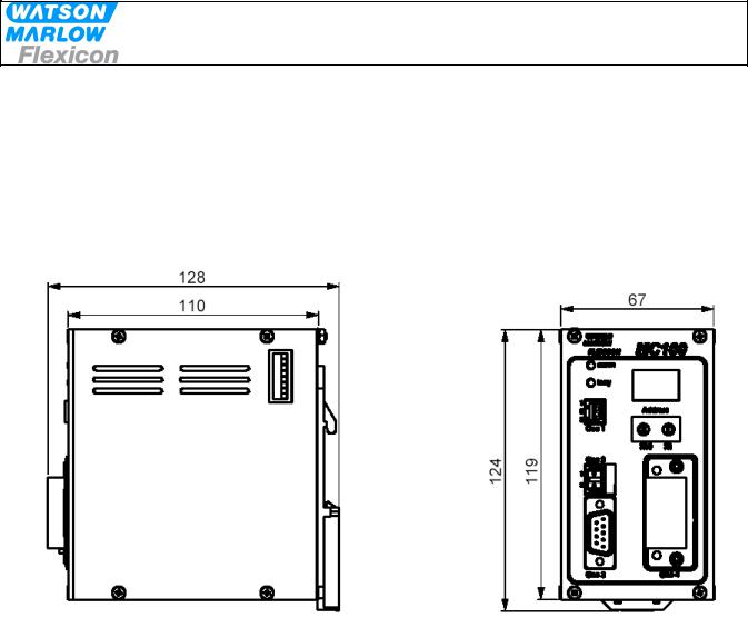
3.1 Dimensions
MC100 Users Manual Profibus DP - rev 4 |
Rev. 4 |
Page 8 of 40 |
|
|
|

Users Manual
MC100
3.2 Specifications
Fieldbus:
-Profibus DP-V1
Pumps:
Up to 16 pumps can be connected to and controlled by one MC100.
The pumps must be able communicate with MC100 via FlexNet protocol.
Material and surface treatment:
-Mounting box made from aluminium.
-All aluminium parts anodised (conductive).
Environmental:
-Ingress protection according to IP30.
-NEMA 1 enclosure.
Mounting:
-MC100 is to be mounted on DIN rail size 35.
Power supply:
-Supply 24 VDC ± 10%.
-Power consumption less than 10 VA.
-Fuse max. 1A
Weight:
-0.5 kg.
MC100 Users Manual Profibus DP - rev 4 |
Rev. 4 |
Page 9 of 40 |
|
|
|

Users Manual
MC100
3.3 Unpacking and inspection of MC100
The MC100 is delivered with
•The MC100
•Declaration of Conformity
•CD-ROM with documentation:
Manual for installation, programming and service of MC100
Documentation and support-files for Anybus Compact Com fieldbus module
Function blocks for Siemens Step7
GDS file for Siemens Step7
The latest revision of this manual and of the function blocks can be downloaded from our Internet site at wmflexicon.dk.
Please check that all ordered items have been received and that no items were damaged during transport. In case of any defects or omissions, please contact WMF or your supplier immediately.
Please verify that the model number stated on the nameplate and the installed fieldbus connector matches your purchase order.
Model number on nameplate |
Fieldbus connector |
MC100 61-120-000 |
Profibus DP-V1 |
3.3.1 Identifying the module
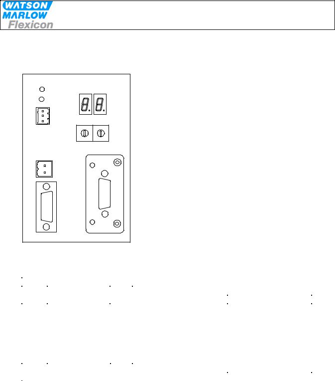
MC100 module:
LED - Comm
LED - Busy
CON 1:
Flexnet connector
CON 2:
Power supply
CON 3:
9-pin SUB D connector
8-bit switch
2-digit LED display
Rotary switches
CON 4:
Fieldbus connector
MC100 Users Manual Profibus DP - rev 4 |
Rev. 4 |
Page 10 of 40 |
|
|
|
Users Manual
MC100
3.3.2 Identifying the parts
-MC100 module.
-Connector for FlexNet.
-Connector for Power Supply.
-Connector for Fieldbus.
3.4Mounting
3.4.1 Choosing a place to mount the MC100
The MC100 must be mounted in an environment that adheres to the specifications in 3.2.
The MC100 must be protected from the following conditions
-Rain and moistures
-Corrosive gasses
-Dust or metallic particles in the air
-Physical shock or vibration
-Magnetic noise (e.g. welding machines, power devices, etc.)
On the left side of the module is a dipswitch (se 3.1), which should be accessible.
MC100 Users Manual Profibus DP - rev 4 |
Rev. 4 |
Page 11 of 40 |
|
|
|
Users Manual
MC100
4 Wiring
MC100 Frontplate |
|
|
||||
COMM |
|
|
|
|
|
|
BUSY |
|
|
|
|
|
|
1 |
|
|
|
|
|
|
2 |
|
|
|
|
|
|
3 |
|
|
Address |
|
|
|
Con 1 |
4 |
5 |
6 |
4 |
5 |
6 |
3 |
|
7 |
3 |
|
7 |
|
|
2 |
|
8 |
2 |
|
8 |
|
1 |
0 |
9 |
1 |
0 |
9 |
X10 X1
Con 2
1 |
2 |
Con 3 Con 4
Connectors / Indicators / Switches
Con1 |
FlexNet |
|
Connector |
Connect with |
|
1 |
/DATA |
I/O |
PHOENIX |
PHOENIX |
|
2 |
GND |
- |
|||
MC 0,5/ 3 –G-2,5THT |
FK MC 0,5/ 3 –ST 2,5 |
||||
3 |
DATA |
I/O |
|||
|
|
The FlexNet connector should be connected to the corresponding terminals on all the pumps, establishing a multidrop network and the last pump should be terminated with a 120 ohm resistor between DATA and /DATA.
Use 0.25 – 0.35 mm2 wires twisted or screened. Terminal tubes must be minimum 8 mm long.
Con2 |
Power Supply |
|
Connector |
Connect with |
1 |
+24V |
IN |
PHOENIX |
PHOENIX |
2 |
0V |
IN |
MC 0,5/ 4 –G-2,5THT |
FK MC 0,5/ 3 –ST 2,5 |
Use 0.5 mm2 wires, terminal tubes must be minimum 8 mm long.
MC100 Users Manual Profibus DP - rev 4 |
Rev. 4 |
Page 12 of 40 |
|
|
|
 Loading...