


505u-gb/3
505U
505U/RL

Declarations
Declaration of |
When this pump unit is used as a stand alone pump it complies with: Machinery Directive 98/37/EC |
conformity |
EN60204-1, Low Voltage Directive 73/23/EEC EN61010-1, EMC Directive 89/336/EEC |
|
EN50081-1/EN50082-1. |
Declaration of When this pump unit is to be installed into a machine or is to be assembled with other machines for Incorporation installations, it must not be put into service until the relevant machinery has been declared in
conformity with the Machinery Directive 98/37/EC EN60204-1.
Responsible person: Dr R Woods, Managing Director, Watson-Marlow Limited, Falmouth, Cornwall TR11 4RU, England. Telephone 01326 370370 Fax 01326 376009.
Three year warranty
Watson-Marlow Limited warrants, subject to the conditions below, through either Watson-Marlow Limited, its subsidiaries, or its authorised distributors, to repair or replace free of charge, including labour, any part of this product which fails within three years of delivery of the product to the end user. Such failure must have occurred because of defect in material or workmanship and not as a result of operation of the product other than in accordance with the instructions given in this manual.
Conditions of and specific exceptions to the above warranty are:
•Consumable items such as tubing and rollers are excluded.
•Products must be returned by pre-arrangement carriage paid to Watson-Marlow Limited, its subsidiaries, or its authorised distributor.
•All repairs or modifications must have been made by Watson-Marlow Limited, its subsidiaries, or its authorised distributors or with the express permission of Watson-Marlow Limited, its subsidiaries, or its authorised distributors.
•Products which have been abused, misused, or subjected to malicious or accidental damage or electrical surge are excluded.
Warranties purporting to be on behalf of Watson-Marlow Limited made by any person, including representatives of Watson-Marlow Limited, its subsidiaries, or its distributors, which do not accord with the terms of this warranty shall not be binding upon WatsonMarlow Limited unless expressly approved in writing by a Director or Manager of Watson-Marlow Limited.
Information for returning pumps
Equipment which has been contaminated with, or exposed to, body fluids, toxic chemicals or any other substance hazardous to health must be decontaminated before it is returned to Watson-Marlow or its distributor.
A certificate included at the rear of these operating instructions, or signed statement, must be attached to the outside of the shipping carton.
This certificate is required even if the pump is unused. If the pump has been used, the fluids that have been in contact with the pump and the cleaning procedure must be specified along with a statement that the equipment has been decontaminated.
Safety
In the interests of safety, this pump and the tubing selected should only be used by competent, suitably trained personnel after they have read and understood this manual, and considered any hazard involved.
Any person who is involved in the installation or maintenance of this equipment should be fully competent to carry out the work. In the UK this person should also be familiar with the Health and Safety at Work Act 1974.
There are dangerous voltages (at mains potential) inside the pump. If access is required, isolate the pump from the mains before removing the cover.
Recommended operating procedures
DO keep delivery and suction lines as short as possible using a minimum number of swept bends.
DO use suction and delivery pipelines with a bore equal to or larger than the bore of the tube fitted in the pumphead. When pumping viscous fluids, the losses caused by increased friction can be overcome by using pipe runs with a cross sectional area several times greater than the pumping element.
DO run at a slow speed when pumping viscous fluids. When using the 501RL pumphead, a 4.8 or 6.4mm bore tube with a 1.6mm wall will give best results. Tube smaller than this will generate a high -friction pressure loss, so reducing the flow. Tube with a larger bore will not have sufficient strength to restitute. Flooded suction will enhance pumping performance in all cases, particularly for materials of a viscous nature. Silicone and Marprene tubing is available with a 2.4mm wall thickness for speeds up to 200rpm. (The rotor will require re-setting to a roller/track gap of 3.8mm.)
2
DO fit an extra length of pump tube in the system to enable tube transfer. This will extend tube life and minimise the downtime of the pumping circuit.
DO keep the track and rollers clean.
The self-priming nature of peristaltic pumps means valves are not required. Any valves fitted must cause no restriction to flow in the pumping circuit.
When using Marprene tubing, after the first 30 minutes of running, re-tension the tube in the pumphead by releasing the tube clamp on the delivery side a little and pulling the tube tight. This is to counteract the normal stretching that occurs with Marprene which can go unnoticed and result in poor tube life.
Tube selection The chemical compatibility list published in the WatsonMarlow catalogue is only a guide. If in doubt about the compatibility of a tube material and the duty fluid, request a tube sample card for immersion trials.
Installation
The 505U/RL is suitable for single phase mains electricity supplies only.
To ensure correct lubrication of the gearbox the pump should be run only while its feet are standing on a horizontal surface. The pump should be positioned to allow a free flow of air around it.
• Set the voltage selector to either 120V for 100-120V 50/60Hz supplies or 240V for 220-240V 50/60Hz supplies.
A mains cable fitted with a moulded plug is supplied with the pump. The wires are colour coded in accordance with the following code:
•220-240V: LiveBrown; Neutral - Blue; Earth - Green/Yellow.
•100-120V: Live - Black; Neutral - White; Earth - Green.
Reduced voltage operation
In areas where voltage is below that specified above, modifications can be made to the pump unit to allow operation under the following minimum voltage levels:
•180V when using the 220-240V setting.
•90V when using the 100-120V setting.
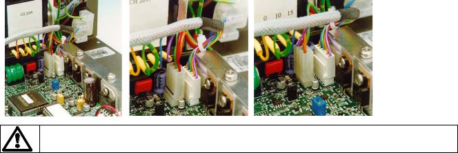
The modification requires the connector J18 on the Control PCB to be reversed. To locate the terminal, isolate the mains supply then remove the pump cover. State A shows the standard voltage setting, whilst State B shows the reduced voltage setting. Any damage caused to the pump in the process of carrying out this modification will not be covered by warranty.
Control PCB |
State A |
State B |
Refer servicing to qualified personnel only.
Troubleshooting
Should the pump fail to operate, make the following checks to determine whether or not servicing is required.
•Check that the power switch is on.
•Check the mains supply is available at the pump.
•Check the voltage selector switch is in the correct position.
•Check the fuse in the mains socket.
•Check that the pump is not stalled by incorrect fitting of tubing.
Manual operation
•Switch power on (drive rear panel).
•Press the Man/Auto key. When the AUT symbol is not flashing the pump is in manual mode.
3

•Change the set speed by pressing the ¿ or À key. The 505U speed control ratio is 110:1. This will give a minimum speed of 2rpm for the 220rpm drive and 0.5 rpm for the 55rpm drive.
•Change direction by pressing the CW/CCW key. Check the flashing CW/CCW symbol for actual direction setting. (CW: clockwise CCW: counterclockwise).
•Select the maximum speed: press the ¿ key and the Max key together. Select the minimum speed: press the À key and the Max key together.
•The keypad has a locking facility to avoid resetting or tampering. If the pump is stopped, press Stop until the padlock symbol illuminates. If the pump is running, press Start until the padlock symbol illuminates. All keys will be disabled except for Start and Stop. Press these keys until the padlock symbol extinguishes to unlock the keypad.
•The pump can be set to automatically restart in its operating state set prior to interruption, or set so that after power is reconnected the pump will remain stopped. To invoke the Auto-restart facility switch off power to the pump at the mains supply. Press the Start key down when the mains supply is switched back on until the ! symbol illuminates. Now press Start to start the pump. This facility can be cancelled by turning the mains supply off and then pressing the Stop key whilst turning the mains supply back on. The ! symbol will not be illuminated.
•Press Start to start the pump. Press Stop to stop the pump.
Automatic operation
Press the Man/Auto key. When the AUT symbol flashes the pump is in manual mode.
The pump is controllable by an analogue process signal of up to 30V or 32mA. The pump will provide an increasing flow rate for rising control signal (non-inverted response ) or an increasing flow rate for falling control signal (inverted response).
•Signal offset is the process signal level which has to be reached in order for the pump rotor to start rotating.
•Signal range is the change in process signal level necessary to produce the required change in pump rotor speed. For example, when using a 4mA to 20mA process signal:
Pump response |
Signal offset |
Signal range |
Non-Inverted |
4mA |
16mA |
Inverted |
20mA |
16mA |
For voltage modes a stable variable DC voltage source can be used in conjunction with a DC voltmeter, (maximum 30V DC). (Refer to 25D pin connector wiring detail as an example of control circuitry) Circuit impedance 100 kohms. Polarity set for non-inverted response. Reverse polarity for inverted response.
For current modes the same DC source can be used in conjunction with a DC milliampere meter, (maximum 32mA). (See 25 pin Dee connector detail). Circuit impedance 250 ohms. Polarity set for non-inverted response. Reverse polarity for inverted response.
Never apply mains voltage across any pins on the 25D socket. Up to 30V may be applied across pins 4 and 17, and 5V TTL on pins 7 and 5, but no voltage should be applied across other pins. Permanent damage, not covered by warranty may result in both instances. Do not use the mains power switch to control the pump for a high repetition of stop/starts. The auto-control facility should be used.
Calibration procedure
•Turn the signal offset potentiometer (marked "Offset" on back panel) clockwise until the slider traverse limit is reached and is signified by a clicking noise. Now turn the potentiometer ten turns anticlockwise. Repeat for the signal range potentiometer. This ensures correct potentiometer set up for calibration.
•Set the process signal offset.
4

•Turn the signal offset potentiometer clockwise to set the pump shaft speed to the desired minimum.
•Set the process signal at its upper range limit (not exceeding 30V or 32mA).
•Turn the signal range potentiometer (marked "Range" on back panel) clockwise to set the drive shaft speed to the desired maximum.
If the process signal or pump speed are set above their designated maximums the pump will be overloaded which is signified by the flashing of AUT. This is an indication of the limiting control and speed levels of the pump. Reset to operate within these levels.
• Repeat the procedure until pump response coincides exactly with the process signal.
Remote control
Stop/Start
Connect remote switch between pins 7 and 15 of the 25D connector. A TTL compatible logic input (Low 0v, High 5V) may be applied to pin 7. Low input stops the pump, high input runs the pump. With no connection, the pump will default to running.
Direction
Connect remote switch between pins 5 and 16 and disable the front panel reversing control by linking pins 6 and 18 of the 25D connector. Open switch for clockwise rotation, close for counter-clockwise. Alternatively a TTL compatible logic input (Low 0, High 5V) may be applied to pin 5. Low input will run the pump in a counter-clockwise direction, High input in a clockwise rotation. No connection; the pump will default to clockwise rotation.
Speed
A remote potentiometer with a nominal value of between 1k and 2k with a minimum of 0.25W should be wired as shown. When using a remote potentiometer, do not apply a voltage/current control input signal at the same time. The speed control signal will require calibration relative to the minimum and maximum settings of the potentiometer. Use the offset and range potentiometers as described under calibration.
Strobe
The state of the pump may be monitored by utilising a 5V Hi Lo signal available at the 25D remote socket on the pump rear panel. The strobe line will change state as soon as the motor starts or stops.
Tachometer output
This facility can be used to indicate motor speed or total the number of motor revolutions.
• 55rpm 2.937kHz
5
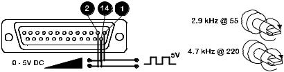
• 220rpm 4.71kHz
Learn and repeat
The 505U incorporates a Learn and Repeat feature, which enables a dose to be memorised and repeated. The dose volume is adjustable via the keypad. Full details are given in the Technical section.
Error messages
If a fault condition is detected in the drive unit it will stop, all keys will be disabled, and the display will flash:
Er1 |
Tachometer fault |
Er2 |
Over temperature error |
Er3 |
EEPROM error |
Er4 |
EEPROM read error |
Er5 |
EEPROM write error |
Er6 |
EEPROM exhausted error. There is a maximum number of times the EEPROM can be written to. If Er6 is displayed, |
|
however, the EEPROM must be replaced. |
Er9 |
RAM corruption error |
Care and maintenance
The only scheduled maintenance of the 505U is to inspect the motor brushes and to replace them before their length is less than 6mm 1/4". The life of the brushes will depend on the duty of the pump, which is expected to be at least 10,000 hours at maximum speed. When the pump needs cleaning, remove the pumphead and use a mild solution of detergent in water. Do not use strong solvents.
If the gearbox is rebuilt you should use 15 ml of the recommended lubricant, which is RD105, this is a SAE 30 mineral oil loaded with molybdenum disulphide to form a soft fluid grease.
Specification
Maximum rotor speed |
55, 220rpm |
Voltage/frequency |
100-120/220-240V 50/60Hz |
Control range |
110:1 |
Power consumption |
100VA |
Shaft Torque |
2.2Nm |
Operating temperature range |
5 to 40C |
Storage temperature range |
-40C to 70C |
Weight |
7.7kg (17Ib) |
Noise |
<70dBA at 1m |
Standards |
EN60529 (IP31) |
|
Machinery Directive 98/37/EC EN60204- 1 |
|
Low Voltage Directive 73/23/EEC EN61010- 1 |
|
EMC Directive:89/336/EEC EN50081-1 / EN50082-1 |
501RL Pumphead
The 501RL pumphead has two spring-loaded working rollers, which automatically compensate for minor variations in tubing wall thickness, giving extended tube life. The 501RL is set during manufacture to accept tubing with wall thicknesses of between 1.6mm and 2.0mm, and internal diameters of up to 8.0mm. It is equipped with a "tool lockable" guard for increased safety. This should be locked shut whilst the pump is in use.
The pumphead can be run clockwise for extended tube life, or anti-clockwise to operate against higher pressures.
Flow rates
Flow rates for the 505U were obtained using silicone tubing with the pumphead rotating clockwise, pumping water at 20C with zero suction and delivery pressures. For critical applications determine flow rates under operating conditions.
Installation
6
 Loading...