


504U/RL
504u-gb-04.pdf

Declarations
Declaration of |
When this pump unit is used as a stand alone pump it complies with: |
Conformity |
Machinery Directive98/37/EC EN60204-1, Low Voltage Directive 73/23/EEC EN61010- |
|
1, EMC Directive 89/336/EEC EN50081-1/EN50082-1. |
Declaration of |
When this pump unit is to be installed into a machine or is to be assembled with |
Incorporation |
other machines for installations, it must not be put into service until the relevant |
|
machinery has been declared in conformity with the Machinery Directive 98/37/EC |
|
EN60204-1. |
Responsible person: Christopher Gadsden, Managing Director, Watson-Marlow Limited, Falmouth, Cornwall TR11 4RU, England. Telephone 01326 370370, Fax 01326 376009.
Three year warranty
Watson-Marlow Limited warrants, subject to the conditions below, through either Watson-Marlow Limited, its subsidiaries, or its authorised distributors, to repair or replace free of charge, including labour, any part of this product which fails within three years of delivery of the product to the end user. Such failure must have occurred because of defect in material or workmanship and not as a result of operation of the product other than in accordance with the instructions given in this manual.
Conditions of and specific exceptions to the above warranty are:
•Consumable items such as tubing and rollers are excluded.
•Products must be returned by pre-arrangement carriage paid to Watson-Marlow Limited, its subsidiaries, or its authorised distributor.
•All repairs or modifications must have been made by Watson-Marlow Limited, its subsidiaries, or its authorised distributors or with the express permission of Watson-Marlow Limited, its subsidiaries, or its authorised distributors.
•Products which have been abused, misused, or subjected to malicious or accidental damage or electrical surge are excluded.
Warranties purporting to be on behalf of Watson-Marlow Limited made by any person, including representatives of Watson-Marlow Limited, its subsidiaries, or its distributors, which do not accord with the terms of this warranty shall not be binding upon Watson-Marlow Limited unless expressly approved in writing by a Director or Manager of Watson-Marlow Limited.
Information for returning pumps
Equipment which has been contaminated with, or exposed to, body fluids, toxic chemicals or any other substance hazardous to health must be decontaminated before it is returned to Watson-Marlow Limited or its distributor.
A certificate included at the rear of these operating instructions, or signed statement, must be attached to the outside of the shipping carton.
This certificate is required even if the pump is unused. If the pump has been used, the fluids that have been in contact with the pump and the cleaning procedure must be specified along with a statement that the equipment has been decontaminated.
Safety
In the interests of safety, this pump and the tubing selected should only be used by competent, suitably trained personnel after they have read and understood this manual, and considered any hazard involved.
Any person who is involved in the installation or maintenance of this equipment should be fully competent to carry out the work. In the UK this person should also be familiar with the Health and Safety at Work Act 1974.
2
There are dangerous voltages (at mains potential) inside the pump. If access is required, isolate the pump from the mains before removing the cover.
Recommended operating procedures
DO keep delivery and suction lines as short as possible using a minimum number of swept bends.
DO use suction and delivery pipelines with a bore equal to or larger than the bore of the tube fitted in the pumphead. When pumping viscous fluids, the losses caused by increased friction can be overcome by using pipe runs with a cross sectional area several times greater than the pumping element.
DO run at a slow speed when pumping viscous fluids. When using the 501RL pumphead, a 4.8 or 6.4mm bore tube with a 1.6mm wall will give best results. Tube smaller than this will generate a high friction pressure loss, so reducing the flow. Tube with a larger bore will not have sufficient strength to restitute. Flooded suction will enhance pumping performance in all cases, particularly for materials of a viscous nature. For improved performance with viscous materials or for lighter suction lift and discharge pressure use 2.4mm wall tubing in the 501RL2 pumphead, for speeds up to 200rpm.
DO keep the track and rollers clean.
DO fit an extra length of pump tube in the system to enable tube transfer. This will extend tube life and minimise the down time of the pumping circuit.
The self-priming nature of peristaltic pumps means valves are not required. Any valves fitted must cause no restriction to flow in the pumping circuit.
When using Marprene or Bioprene tubing, after the first 30 minutes of running, re-tension the tube in the pumphead by releasing the tube clamp on the delivery side a little and pulling the tube tight. This is to counteract the normal stretching that occurs with Marprene and Bioprene, which can go unnoticed and result in reduced tube life.
Tube selection The chemical compatibility list published in the Watson-Marlow catalogue is only a guide. If in doubt about the compatibility of a tube material and the duty fluid, request a tube sample card for immersion trials.
Installation
The 504U/RL is suitable for single phase mains electricity supplies only.
To ensure correct lubrication of the gearbox the pump should be run only while its feet are standing on a horizontal surface. The pump should be positioned to allow a free flow of air around it.
•Remove the small transparent plate on the rear panel to gain access to the voltage selector and terminal block.
•Set the voltage selector switch to either 120V for 100-120V 50/60Hz single phase AC supplies or 240V for 220-240V 50/60Hz single phase AC supplies.
•Route the mains supply cable through the entry point to the right of the recess and couple the cable to the terminal block as shown on the rear panel.
•The cable entry accepts three core 0.75 square millimetre PVC sheathed mains cable (via the screw adaptor supplied) so that a mains lead can be used.
•Ensure that the mains lead is securely retained in the strain relief gland so that IP55 ingress protection is maintained.
•Securely replace the transparent plate and the gasket over the recess.
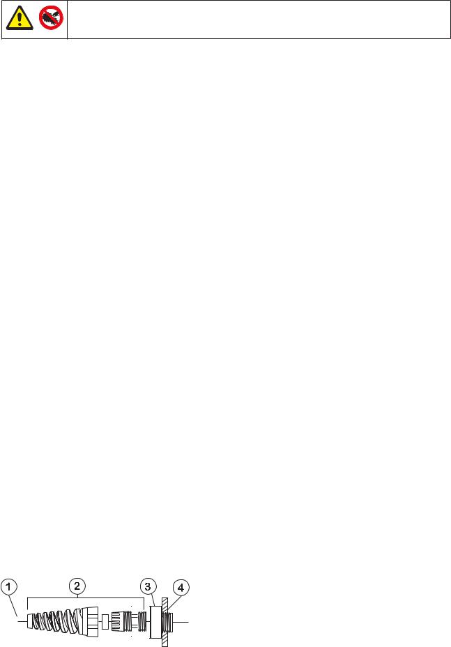
1 Power cable 5-8mm O.D. (outside diameter)
2 Strain relief gland SL 0020
3 Adaptor MR0678T
4 M20 Conduit thread for direct conduit connection, through back panel
3
Ingress protection standard will be compromised if fittings are not correctly replaced.
Rear panel recess
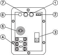
The pump rear panel recess houses the following:
1 |
|
|
|
potentiometer 2 Tachometer switch 3 Voltage selection switch 4 Terminal block |
Signal offset |
||||
5 |
Fuse holder 6 |
Signal overload LED 7 Signal range potentiometer. |
||
Troubleshooting
Should the unit fail to operate, make the following checks to determine whether or not servicing is required.
•Check that the power switch is on.
•Check the mains supply is available at the pump unit.
•Check the voltage selector switch is in the correct position.
•Check the fuse in the mains socket.
•Check that the pump is not stalled by incorrect fitting of tubing.
Manual operation
Start up direction Start the pump by turning the Forward/Off/Reverse switch to the required direction of rotation. The preferred direction of rotation is clockwise (with fluid entering at the bottom of the right of the pumphead), which will ensure the longest possible tube life. To operate against higher pressures, use counterclockwise rotation.
Prime To prime the pump at maximum speed turn the Auto/Manual/Max switch on the front panel to its Max position. When released the switch will return to its Manual position.
Speed control The speed setting dial is calibrated in percentage of maximum speed and has a locking knob to prevent accidental speed changes.
Stop Stop the pump by turning the Forward/Off/Reverse switch to its central Off position. To change the direction of flow, turn the Forward/Off/Reverse switch to its central Off position until the pumphead rotor stops, and turn it to the required direction of rotation.
If returning from auto control to manual control, it is not necesssary to disconnect the process signal from the pump or adjust the calibration potentiometers.
4
Automatic operation
Set the Auto/Man/Max switch to Auto.
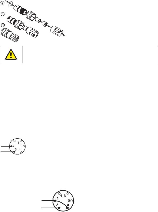
For all auto and remote control operations, the drive is supplied with a 6 pin waterproof connector (UP 0055).
Correct assembly of the 6 pin plug is essential or the ingress protection standard will be compromised. Never apply mains voltage across any pins on the 6 pin socket. Up to 30V may be applied across pins 2 and 3, but not across other pins because permanent damage, not covered by warranty may result.
The pump is controllable by an analogue process signal of up to 30V or 32mA. The pump will provide an increasing flow rate for rising control signals (non-inverted response) or an increasing flow rate for falling control signal
(inverted response).
•Signal offset is the process signal level which has to be reached in order for the pump rotor to start rotating.
•Signal range is the change in process signal level necessary to produce the required change in pump rotor speed.
For example, when using a 4mA to 20mA process signal:
Pump Response |
Signal Offset |
Signal range |
Non-Inverted |
4mA |
16mA |
Inverted |
20mA |
16mA |
For voltage modes a stable variable DC voltage source can be used in conjunction with a DC voltmeter, (maximum 30V DC) or a remote potentiometer. Polarity set for non-inverted response. Reverse polarity for inverted response.
Voltage signal
Input impedance 220 kohm
Response |
Range V |
Offset V |
Pin 2 |
Pin 3 |
Non-inverted |
5 to 30 |
0 to 30 |
– |
+ |
inverted |
5 to 30 |
0 to 30 |
+ |
– |
For current modes the same DC source can be used in conjunction with a DC milliampere meter. Polarity set for non-inverted response. Reverse polarity for inverted response.
Current signal
Input impedance 250 ohm
5
Response |
Range mA |
Offset mA |
Pin 2 |
Pin 3 |
Non-inverted |
12 to 30 |
0 to 30 |
– |
+ |
inverted |
12 to 30 |
0 to30 |
+ |
– |
Calibration for auto control
Ensure the correct wiring of the 6 pin plug and insert the plug into the socket at the rear of the pump.
•Remove the rear panel recess window.Turn the signal offset potentiometer clockwise until the slider traverse limit is reached and is signified by a clicking noise. Now turn the potentiometer ten turns anticlockwise.
•Repeat for the signal range potentiometer. This ensures correct potentiometer set up for calibration.Set the process signal offset.
•Turn the signal offset potentiometer clockwise to set the drive shaft speed to the desired minimum.
•Set the process signal at its upper range limit (not exceeding 30V or 32mA).
•Turn the signal range potentiometer clockwise to set the drive shaft speed to the desired maximum.
•Repeat the procedure until pump response coincides exactly with the process signal.
If the signal rises above its designated maximum, the action of the signal conditioner will be to hold the motor to maximum speed at the MAX setting indicated by the flashing of the LED indicator. If the signal rises above 30V, permanent damage, not covered by warranty, may result.
Securely replace the rear panel recess on the back of the pump ensuring the gasket is in the correct position. This will avoid the ingress protection standard of the pump unit being compromised.
Remote control
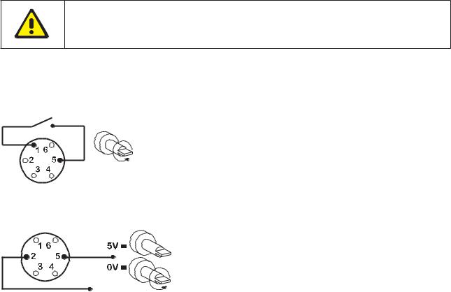
Stop/Start
Connect remote switch between pins 1 and 5 of the 6 pin socket. Close contact to stop the pump, open to run.
A TTL compatible logic input (Low 0V, High 5V) may be applied to pin 5 (pin 2 common) with 5V High = stop, 0V low = run).
6
 Loading...