


WATSON-MARLOW BREDEL MANUALS
m-620un-u-sn-s-gb-01
Watson-Marlow 620UN / 620U, 620SN / 620S pumps
Contents
1 |
Declaration of conformity |
3 |
16 |
Setup |
|
33 |
|
2 |
Declaration of incorporation |
3 |
|
16.1 |
Trim |
34 |
|
3 |
Five-year warranty |
3 |
|
16.2 |
Analogue |
35 |
|
4 |
When you unpack your pump |
5 |
|
|
16.2.1 Input 1: speed |
36 |
|
5 |
Information for returning pumps |
6 |
|
|
16.2.2 Trim |
38 |
|
6 |
Peristaltic pumps - an overview |
6 |
|
|
16.2.3 Menu |
38 |
|
7 |
Safety notes |
7 |
|
16.3 |
Display |
38 |
|
8 |
Pump specifications |
9 |
|
16.4 |
Outputs |
39 |
|
|
8.1 |
Pressure capability |
14 |
|
16.5 |
Remote stop |
41 |
|
8.2 |
Dimensions |
15 |
|
16.6 |
Auto-restart |
42 |
9 |
Good pump installation practice |
16 |
|
16.7 |
Set maximum allowed |
|
|
|
9.1 |
General recommendations 16 |
|
|
speed |
43 |
|
|
9.2 |
Do’s and do not’s |
17 |
|
16.8 |
Set minimum allowed |
|
10 |
Connecting this product to a |
|
|
|
speed |
44 |
|
|
power supply |
18 |
|
16.9 |
Scrolling |
44 |
|
11 |
Start-up check list |
19 |
|
16.10 |
Date and time |
45 |
|
12 |
Switching the pump on for the |
|
|
16.11 |
Backlight |
46 |
|
|
first time |
20 |
|
16.12 |
ROM |
46 |
|
13 |
Switching the pump on in |
|
|
16.13 |
Language |
47 |
|
|
subsequent power cycles |
|
|
16.14 |
Defaults |
47 |
|
|
(if not in auto-restart mode) |
22 |
|
16.15 |
Security code |
48 |
|
14 |
Manual operation |
23 |
|
16.16 |
Exit |
49 |
|
|
14.1 |
Keypad functions, |
|
17 MemoDose and calibration |
50 |
||
|
|
620UN, 620U |
23 |
|
17.1 |
Changing dosing speed |
51 |
|
14.2 |
Keypad functions, |
|
|
17.2 |
Footswitch operation and |
|
|
|
620SN, 620S |
25 |
|
|
other remote inputs and |
|
|
14.3 |
Speed |
28 |
|
|
outputs with MemoDose |
52 |
|
14.4 |
Direction |
28 |
|
17.3 |
Flow calibration |
52 |
|
14.5 |
Keypad lock |
28 |
|
17.4 |
Exit |
54 |
|
14.6 |
Keypad beep |
28 |
18 Pin out details |
54 |
||
|
14.7 |
To reset defaults |
29 |
19 |
Exit |
|
55 |
|
14.8 |
To reset language |
29 |
20 |
Automatic control wiring |
|
|
|
14.9 |
Backlight |
29 |
|
using the 620N module |
56 |
|
|
14.10 |
Auto-restart |
29 |
|
20.1 |
620N module removal |
|
|
14.11 |
Manual operation and |
|
|
|
and replacement |
56 |
|
|
remote digital inputs |
|
|
20.2 |
Wiring up |
57 |
|
|
and outputs |
30 |
|
20.3 |
Speed: analogue input |
60 |
15 |
Main menu |
31 |
|
20.4 |
Speed: analogue output |
61 |
|
|
15.1 |
Keypad functions in |
|
|
20.5 |
Tachometer frequency |
|
|
|
menu screens |
31 |
|
|
output |
61 |
|
15.2 |
Main menu entry |
31 |
|
20.6 |
Run/stop input |
62 |
Watson-Marlow 620UN, 620U, 620SN, 620S User Manual |
1 |
20.7 Direction input |
62 |
20.8Auto / manual toggle
|
input |
62 |
20.9 |
MemoDose input |
63 |
20.10 |
Leak detection input |
63 |
20.11 |
Outputs 1, 2, 3, 4 |
64 |
20.12 |
Supply voltages |
64 |
21 Automatic control wiring |
|
|
without the 620N module |
66 |
|
21.1 |
Speed: analogue input |
67 |
21.2 |
Speed: analogue output |
68 |
21.3Tachometer frequency
|
output |
68 |
21.4 |
run/stop input |
69 |
21.5 |
Direction input |
70 |
21.6Auto / manual toggle
|
|
input |
70 |
|
21.7 |
MemoDose input |
71 |
|
21.8 |
Leak detection input |
71 |
|
21.9 |
Pump status outputs |
72 |
|
|
21.9.1 Logic output 1 |
72 |
|
|
21.9.2 Logic output 2 |
73 |
|
|
21.9.3 Logic output 3 |
74 |
|
|
21.9.4 Logic output 4 |
74 |
|
21.10 |
Supply voltages |
75 |
22 |
Automatic control and operation 76 |
||
23 |
Troubleshooting |
78 |
|
|
23.1 |
Error codes |
79 |
24 |
Drive maintenance |
80 |
|
25 |
Drive spares |
80 |
|
26 |
620RE MarkII, 620RE4 MarkII and |
||
|
620R MarkII pumpheads |
81 |
|
26.1620RE, 620RE4 and 620R
Key safety information |
81 |
26.2620RE, 620RE4 and 620R
safe-guarding 81
26.3620RE, 620RE4 and 620R
pumping conditions |
82 |
26.4620RE, 620RE4 and 620R
pump installation |
82 |
26.5620RE, 620RE4 and 620R
|
general operation |
83 |
26.6 |
620RE and 620RE4 |
|
|
tube element loading |
84 |
26.7 |
620R continuous |
|
|
tube loading |
86 |
26.8620RE, 620RE4 and 620R tube element or
continuous tube removal 87
26.9620RE, 620RE4 and 620R
|
|
maintenance |
87 |
|
26.10 |
620RE, 620RE4 and 620R |
|
|
|
CIP and SIP |
90 |
|
26.11 |
620RE, 620RE4 and 620R |
|
|
|
pumphead spares |
91 |
27 |
620RE, 620RE4 and 620R |
|
|
|
performance data |
93 |
|
|
27.1 |
620RE, 620RE4 and 620R |
|
|
|
flow rates |
94 |
28 |
620R tubing product codes |
96 |
|
29 |
620RE and 620RE4 LoadSure |
|
|
|
tube element product codes |
97 |
|
30 |
620 series pumping accessories |
98 |
|
31 |
Trademarks |
99 |
|
32 |
Warning not to use pumps in |
|
|
|
patient-connected applications |
99 |
|
33 |
Publication history |
99 |
|
34 |
Decontamination certificate |
100 |
|
Watson-Marlow 620UN, 620U, 620SN, 620S User Manual |
2 |

UN, U, SN, S 1 Declaration of conformity
This declaration was issued for Watson-Marlow 620UN, 620U, 620SN and 620S pumps on September 19, 2005. When this pump unit is used as a stand-alone pump it complies with: Machinery Directive 2006/42/EC, EMC Directive 2004/108/EC.
This pump is ETL listed: ETL control number 3050250. Cert to CAN/CSA std C22.2 No 61010-1. Conforms to UL std 61010A-1.
See 8 Pump specifications.
UN, U, SN, S 2 Declaration of incorporation
When this pump unit is to be installed into a machine or is to be assembled with other machines for installations, it must not be put into service until the relevant machinery has been declared in conformity with the Machinery Directive 2006/42.
Responsible person: Christopher Gadsden, Managing Director, Watson-Marlow Limited, Falmouth, Cornwall TR11 4RU, England. Telephone +44 (0) 1326 370370 Fax +44 (0) 1326 376009.
The information in this user guide is believed to be correct at the time of publication. However, Watson-Marlow Limited accepts no liability for errors or omissions. Watson-Marlow Bredel has a policy of continuous product improvement, and reserves the right to alter specifications without notice. This manual is intended for use only with the pump it was issued with. Earlier or later models may differ. The most up-to-date manuals appear on the Watson-Marlow website: http://www.watson-marlow.com
3 Five-year warranty
UN, U, SN, S
520 cased pumps, 620 cased pumps and 720 cased pumps
For any 520, 620 or 720 cased pump purchased after 1 January 2007, WatsonMarlow Limited (“Watson-Marlow”) warrants, subject to the conditions and exceptions below, through either Watson-Marlow, its subsidiaries, or its authorised distributors, to repair or replace free of charge, any part of the product which fails within five years of the day of manufacture of the product. Such failure must have occurred because of defect in material or workmanship and not as a result of operation of the product other than in normal operation as defined in this pump manual.
Watson-Marlow 620UN, 620U, 620SN, 620S User Manual |
3 |
Watson-Marlow shall not be liable for any loss, damage, or expense directly or indirectly related to or arising out of the use of its products, including damage or injury caused to other products, machinery, buildings, or property, and Watson-Marlow shall not be liable for consequential damages, including, without limitation, lost profits, loss of time, inconvenience, loss of product being pumped, and loss of production. This warranty does not obligate Watson-Marlow to bear any costs of removal, installation, transportation, or other charges which may arise in connection with a warranty claim.
Conditions of and specific exceptions to the above warranty are:
Conditions
Products must be returned by pre-arrangement, carriage-paid, to WatsonMarlow, or a Watson-Marlow approved service centre.
All repairs or modifications must have been made by Watson-Marlow Limited, or a Watson-Marlow approved service centre or with the express permission of Watson-Marlow.
Warranties purporting to be on behalf of Watson-Marlow made by any person, including representatives of Watson-Marlow, its subsidiaries, or its distributors, which do not accord with the terms of this warranty shall not be binding upon Watson-Marlow unless expressly approved in writing by a Director or Manager of Watson-Marlow.
Exceptions
The warranty shall not apply to repairs or service necessitated by normal wear and tear or for lack of reasonable and proper maintenance.
All tubing and pumping elements as consumable items are excluded.
Products which, in the judgment of Watson-Marlow, have been abused, misused, or subjected to malicious or accidental damage or neglect are excluded.
Electrical surge as a cause of failure is excluded.
Chemical attack is excluded
All pumphead rollers are excluded.
The 620R family of pumpheads are excluded from all warranty when pumping above 2 bar while above 165rpm.
Pumpheads from the 313/314 and the Microcassette ranges and any 701 extension pumpheads are excluded and retain their one-year standard pumphead warranty. The drive they are attached to is subject to the five-year warranty as set out here.
Ancillaries such as leak detectors are excluded.
Watson-Marlow 620UN, 620U, 620SN, 620S User Manual |
4 |

UN, U, SN, S 4 When you unpack your pump
Unpack all parts carefully, retaining the packaging until you are sure all components are present and in good order. Check against the components supplied list, below.
Packaging disposal
Dispose of packaging materials safely, and in accordance with regulations in your area. The outer carton is made of corrugated cardboard and can be recycled.
Inspection
Check that all components are present. Inspect components for damage in transit. If anything is missing or damaged, contact your distributor immediately.
Components supplied
620UN, 620U, 620SN and 620S pumps are dedicated to 620R series pumpheads. Pumps are supplied as:
Dedicated 620R pump drive unit fitted with 620R, 620RE or 620RE4 pumphead (see 8. Pump specifications).
A 620N module providing pump ingress protection to IP66, NEMA 4X, if a 620UN or 620SN.
Note: the module is attached for transit, but must be removed to allow wiring up, voltage selection and fuse inspection and then re-affixed before the pump is operated.
The designated mains power lead for your pump
PC-readable CDROM containing these operating instructions
Quick Start manual
Note: Some versions of this product will include components different from those listed above. Check against your purchase order.
Storage
This product has an extended shelf life. However, care should be taken after storage to ensure that all parts function correctly. Users should be aware that the pump contains a battery with an unused life of seven years. Long-term storage is not recommended for peristaltic pump tubing. Please observe the storage recommendations and use-by dates which apply to tubing you may wish to bring into service after storage.
Watson-Marlow 620UN, 620U, 620SN, 620S User Manual |
5 |

UN, U, SN, S 5 Information for returning pumps
Equipment which has been contaminated with, or exposed to, body fluids, toxic chemicals or any other substance hazardous to health must be decontaminated before it is returned to Watson-Marlow or its distributor.
A certificate included at the rear of these operating instructions, or signed statement, must be attached to the outside of the shipping carton. This certificate is required even if the pump is unused.
If the pump has been used, the fluids that have been in contact with the pump and the cleaning procedure must be specified along with a statement that the equipment has been decontaminated.
UN, U, SN, S 6 Peristaltic pumps - an overview
Peristaltic pumps are the simplest pump, with no valves, seals or glands to clog or corrode. The fluid contacts only the bore of a tube, eliminating the risk of the pump contaminating the fluid, or the fluid contaminating the pump. Peristaltic pumps can run dry.
How they work
A compressible tube is squeezed between a roller and a track on an arc of a circle, creating a seal at the point of contact. As the roller advances along the tube, the seal also advances. After the roller has passed, the tube returns to its original shape, creating a partial vacuum which is filled by fluid drawn from the inlet port.
Before the roller reaches the end of the track, a second roller compresses the tube at the start of the track, isolating a packet of fluid between the compression points. As the first roller leaves the track, the second continues to advance, expelling the packet of fluid through the pump’s discharge port. At the same time, a new partial vacuum is created behind the second roller into which more fluid is drawn from the inlet port.
Backflow and siphoning do not occur, and the pump effectively seals the tube when it is inactive. No valves are needed.
The principle may be demonstrated by squeezing a soft tube between thumb and finger and sliding it along: fluid is expelled from one end of the tube while more is drawn in at the other.
Animal digestive tracts function in a similar way.
Suitable applications
Peristaltic pumping is ideal for most fluids, including viscous, shear-sensitive, corrosive and abrasive fluids, and those containing suspended solids. They are especially useful for pumping operations where hygiene is important.
Peristaltic pumps operate on the positive displacement principle. They are particularly suitable for metering, dosing and dispensing applications. Pumps are easy to install, simple to operate and inexpensive to maintain.
Watson-Marlow 620UN, 620U, 620SN, 620S User Manual |
6 |
UN, U, SN, S 7 Safety notes
In the interests of safety, this pump and the tubing selected should only be used by competent, suitably trained personnel after they have read and understood this manual, and considered any hazard involved. If the pump is used in a manner not specified by Watson-Marlow Ltd, the protection provided by the pump may be impaired.
This symbol, used on the pump and in this manual, means: Caution, refer to accompanying documents.
This symbol, used on the pump and in this manual, means: Do not allow fingers to contact moving parts.
This symbol, used on the pump and in this manual, means: Recycle this product under the terms of the EU Waste Electrical and Electronic Equipment (WEEE) Directive.
There is a user-replaceable type T5A H 250V fuse in the fuseholder in the centre of the switchplate at the back of the pump. The 620N module must
be removed, if a 620DiN, to allow access to the switchplate. See 20.1 620N module removal and replacement. There are thermal fuses within the pump which self-reset within 60 seconds; if they trip an error code is displayed. This pump contains no user-serviceable fuses or parts.
Fundamental work with regard to lifting, transportation, installation, starting-up, maintenance and repair should be performed by qualified per-
sonnel only. The unit must be isolated from mains power while work is being carried out.
Watson-Marlow 620UN, 620U, 620SN, 620S User Manual |
7 |

Any person who is involved in the installation or periodic maintenance of this equipment should be suitably skilled or instructed and supervised using a safe system of work. In the UK this person should also be familiar with the Health and Safety at Work Act 1974.
There are moving parts inside the pumphead. Before opening the toolunlockable pumphead guard, ensure that the following safety directions are followed.
Ensure that the pump is isolated from the mains power.
Ensure that there is no pressure in the pipeline.
If a tube failure has occurred, ensure that any fluid in the pumphead has been allowed to drain to a suitable vessel, container or drain.
Ensure that protective clothing and eye protection are worn if hazardous fluids are pumped.
Primary operator protection from rotating parts of the pump is provided by the pumphead safeguard. Note that safeguards differ, depending on the type of pumphead. See the pumphead section of this manual: 26.
Secondary operator protection from rotating parts of the pump is provided by electrical interlocking of the pumphead guard. This function will stop the pump if the guard is inadvertently opened while the pump is running. For details of permissible pumphead orientations, see the pumphead section of this manual: 26.
This product does not comply with the ATEX directive and must not be used in explosive atmospheres.
This pump must be used only for its intended purpose. The pump must be accessible at all times to facilitate operation and maintenance. Access points must not be obstructed or blocked. The pump’s mains plug is the disconnecting device (for isolating the motor drive from the mains supply in an emergency). Do not position the pump so that it is difficult to disconnect the mains plug. Do not fit any devices to the drive unit other than those tested and approved by Watson-Marlow. Doing so could lead to injury to persons or damage to property for which no liability can be accepted.
If hazardous fluids are to be pumped, safety procedures specific to the particular fluid and application must be put in place to protect against injury to persons.
The exterior surfaces of the pump may get hot during operation. Do not take hold of the pump while it is running. Let it cool after use before handling it.
No attempt should me made to run the drive without a pumphead fitted.
The pump weighs more than 18kg (the exact weight depends on model and pump- head—see 8 Pump specifications). Lifting should be performed according to standard Health and Safety guidelines. Finger recesses are built into the sides of the lower shell for convenience in lifting; in addition, the pump can conveniently be lifted by grasping the pumphead and (where fitted) the 620N module at the rear of the pump.
Watson-Marlow 620UN, 620U, 620SN, 620S User Manual |
8 |

|
8 Pump specifications |
UN, SN |
Labels fixed to the rear of the pump contain manufacturer and contact details, prod- |
|
uct reference number, serial number and model details. |
|
UN, U, SN, S The same information is carried on the drive’s backplate, accessible when the 620N module is removed. The picture below is how a 620SN looks from the box. The number of connectors varies according to the model.
Watson-Marlow 620UN, 620U, 620SN, 620S User Manual |
9 |

UN, U 620UN, IP66 NEMA 4X model, and 620U, IP31 model
This pump can be controlled from the keypad or remotely. It features:
Manual control
Speed adjustment; run and stop; direction control; "max" key for rapid priming.
Remote control
The pump can be digitally controlled with a contact closure or logic input signal to operate the pump.
Analogue control
The pump speed can be controlled through an analogue signal input in the ranges 0-10V, 1-5V or 4-20mA.
Outputs
A 0-10V, 4-20mA or 0-1258Hz output signal provides feedback of the pump speed. There are four digital (620U) or relay (620UN) status outputs which can be configured in software for a variety of pump parameters.
MemoDose
Allows precise repeat dosing. Stores in memory a pulse count from the motor. This count is repeated each time START is pressed to provide a single-shot dose.
Calibration
Uses the same pulse count as MemoDose. The corresponding pumped volume can be entered to calibrate the flow of the pump.
Guard switch
Primary operator protection from rotating parts of the pump is provided by the fixed guard. Secondary operator protection from rotating parts of the pump is provided by indicator-only switching of the pumphead guard.
SN, S 620SN, IP66 NEMA 4X model, and 620S, IP31 model
This pump operates by manual control only. There are no external control connections. All pump functions are controlled from the keypad. It features:
Manual control
Speed adjustment; run and stop; direction control; "max" key for rapid priming.
MemoDose
Allows precise repeat dosing. Stores in memory a pulse count from the motor. This count is repeated each time START is pressed to provide a single-shot dose.
Calibration
Uses the same pulse count as MemoDose. The corresponding pumped volume can be entered to calibrate the flow of the pump.
Guard switch
Primary operator protection from rotating parts of the pump is provided by the fixed guard. Secondary operator protection from rotating parts of the pump is provided by indicator-only switching of the pumphead guard.
Watson-Marlow 620UN, 620U, 620SN, 620S User Manual |
10 |
UN, U, SN, S |
IP (Ingress Protection) and NEMA definitions |
|
|
||||||
|
|
|
|
|
|
|
|
|
|
|
|
|
|
|
|
|
|
|
|
|
|
|
IP |
|
|
|
|
NEMA |
|
|
|
|
1st Digit |
|
2nd Digit |
|
|
||
|
|
|
|
|
|
|
|||
|
|
|
Protected against |
|
|
|
|
|
|
|
|
|
ingress of solid objects |
|
Protection against |
|
Indoor use to provide a |
||
|
|
|
with a diameter of |
|
|
||||
|
|
|
|
dripping water falling |
|
degree of protection |
|||
|
|
|
more than 2.5mm. |
|
|
||||
|
|
3 |
1 |
vertically. No harmful |
2 |
against limited |
|||
|
|
|
Tools, wires etc with a |
|
effect must be |
|
amounts of falling |
||
|
|
|
thickness of more than |
|
|
||||
|
|
|
|
produced |
|
water and dirt |
|||
|
|
|
2.5mm are prevented |
|
|
||||
|
|
|
|
|
|
|
|
||
|
|
|
from approach |
|
|
|
|
|
|
|
|
|
Protected against |
|
|
|
|
|
|
|
|
|
|
|
|
|
|
Indoor use to provide a |
|
|
|
|
harmful dust deposits. |
|
|
|
|
|
degree of protection |
|
|
|
Ingress of dust is not |
|
|
Protection against |
|
12 |
against dust, falling |
|
|
|
totally prevented but |
|
|
water projected from a |
|
|
dirt and dripping, non- |
|
|
|
the dust must not |
|
|
nozzle against the |
|
|
corrosive liquids |
|
|
5 |
enter in sufficient |
|
5 |
equipment (enclosure) |
|
|
Indoor use to provide a |
|
|
quantity to interfere |
|
from any direction. |
|
|
|||
|
|
|
with satisfactory |
|
|
There must be no |
|
|
degree of protection |
|
|
|
operation of the |
|
|
harmful effect (water |
|
13 |
against dust and |
|
|
|
equipment. Complete |
|
|
jet) |
|
spraying of water, oil |
|
|
|
|
protection against |
|
|
|
|
|
and non-corrosive |
|
|
|
contact |
|
|
|
|
|
coolants |
|
|
|
|
|
|
|
|
|
Indoor or outdoor use* |
|
|
|
|
|
|
|
|
|
to provide a degree of |
|
|
|
|
|
|
Protection against |
|
|
protection against |
|
|
|
Protection against |
|
|
heavy seas or powerful |
|
|
splashing water, wind- |
|
|
|
ingress of dust (dust- |
|
|
water jets. Water must |
|
|
blown dust and rain, |
|
|
6 |
tight). Complete |
|
6 |
not enter the |
|
4X |
hose-directed water; |
|
|
|
protection against |
|
|
equipment (enclosure) |
|
|
undamaged by the |
|
|
|
contact |
|
|
in harmful quantities |
|
|
formation of ice on the |
|
|
|
|
|
|
(splashing over) |
|
|
enclosure. (Resist |
|
|
|
|
|
|
|
|
|
corrosion: 200-hour |
|
|
|
|
|
|
|
|
|
salt spray) |
|
|
|
|
|
|
|
|
|
|
* 620 cased pumps are rated to NEMA 4X (indoor use) only.
Watson-Marlow 620UN, 620U, 620SN, 620S User Manual |
11 |

Pump specifications
Control range (turndown ratio) |
0.1-265rpm (2650:1) |
|
Supply voltage/frequency |
Filtered 100-120V/200-240V 50/60Hz 1ph |
|
|
|
|
|
±10% of nominal voltage. A well |
|
|
regulated electrical mains supply is |
|
Maximum voltage fluctuation |
required along with cable connections |
|
|
conforming to the best practice of noise |
|
|
immunity |
|
Installation category |
II |
|
(overvoltage category) |
||
|
||
Power consumption |
250VA |
|
|
|
|
Full load current |
<1.1A at 230V; <2.2A at 115V |
|
Eprom version |
Accessible through pump software |
|
|
|
|
|
IP66 to BS EN 60529; Equivalent to |
|
|
NEMA 4X to NEMA 250* (indoor use). |
|
|
Suitable for heavy industrial, process |
|
Enclosure rating - 620UN, 620SN |
and filthy environments. The drive uses |
|
|
a Gore membrane vent to equalise the |
|
|
pressure inside the enclosure and to |
|
|
prevent ingress of water and corrosive |
|
|
vapours. |
|
|
IP31 to BS EN 60529. Equivalent to |
|
|
NEMA 2, suitable for indoor use. |
|
Enclosure rating - 620U, 620S |
Protected against dripping water and |
|
|
falling dirt. May be wiped with a damp |
|
|
cloth, but should not be immersed. |
|
Pumphead options |
620R, 620RE, 620RE4 |
|
Operating temperature range |
5C to 40C, 41F to 104F |
|
Storage temperature range |
-25C to 65C, -13F to 149F |
|
Maximum altitude |
2,000m, 6,560ft |
|
Humidity (non-condensing) |
80% up to 31C, 88F, decreasing |
|
(620U, 620S) |
linearly to 50% at 40C, 104F |
|
Humidity (condensing) |
10% - 100% RH |
|
(620UN, 620SN) |
||
|
||
Weight |
See table on previous page |
|
Noise |
<70dB(A) at 1m |
|
|
|
|
* Protect from prolonged UV exposure. |
|
Watson-Marlow 620UN, 620U, 620SN, 620S User Manual |
12 |

Standards
|
Safety of machinery—electrical equipment of machines: |
|
|
BS EN 60204-1 |
|
|
Safety requirements for electrical equipment for |
|
|
measurement, control and laboratory use: |
|
|
BS EN 61010-1 incorporating A2 Category 2, Pollution degree 2 |
|
|
Degrees of protection provided by enclosures (IP code): |
|
|
BS EN 60529 amendments 1 and 2 |
|
|
Conducted emissions: |
|
|
BS EN 55011 A1 and A2, Class A, called by BS EN 61000-6-4 |
|
|
Radiated emissions: |
|
|
BS EN 55011 A1 and A2, Class A, called by BS EN 61000-6-4 |
|
EC |
Electrostatic discharge: BS EN 61000-4-2 |
|
Radiated RF immunity: |
||
harmonised |
||
standards |
BS EN 61000-4-3 A1 and A2, called by BS EN 61000-6-2 |
|
|
Fast transient burst: |
|
|
BS EN 61000-4-4 A1 and A2, Level 3 (2kV), |
|
|
called by BS EN 61000-6-2 |
|
|
Surge immunity: |
|
|
BS EN 61000-4-5 A1 and A2, called by BS EN 61000-6-2 |
|
|
Conducted RF immunity: |
|
|
BS EN 61000-4-6, called by BS EN 61000-6-2 |
|
|
Voltage dips and interruptions: |
|
|
BS EN 61000-4-11, called by BS EN 61000-6-2 |
|
|
|
|
|
Mains harmonics: BS EN 61000-3-2 A2 |
|
|
Pumps and pump units for liquids—common safety |
|
|
requirements: BS EN 809 |
|
|
UL 61010A-1 |
|
Other |
CAN/CSA-C22.2 No 61010-1 |
|
Conducted emissions FCC 47CFR, Part 15.107 |
||
standards |
||
Radiated emissions FCC 47CFR, Part 15 |
||
|
||
|
|
|
|
NEMA 4X to NEMA 250 (indoor use) for IP66 products only |
|
|
|
Watson-Marlow 620UN, 620U, 620SN, 620S User Manual |
13 |
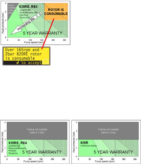
8.1 Pressure capability
0-4 bar higher pressure pumping
This pump’s default running speed is 165rpm. It can be run at any speed up to 265rpm. Please note, however:
The 620RE and 620RE4 rotor warranty is limited to 2 bar from 165rpm to 265rpm.
A warning is displayed when the user sets the speed above 165rpm. Note: Applies to 620RE MarkII and 620RE4 MarkII pumpheads only.
The pump’s software records the duration of operation above 165rpm.
0-2 bar pressure pumping
Watson-Marlow 620UN, 620U, 620SN, 620S User Manual |
14 |
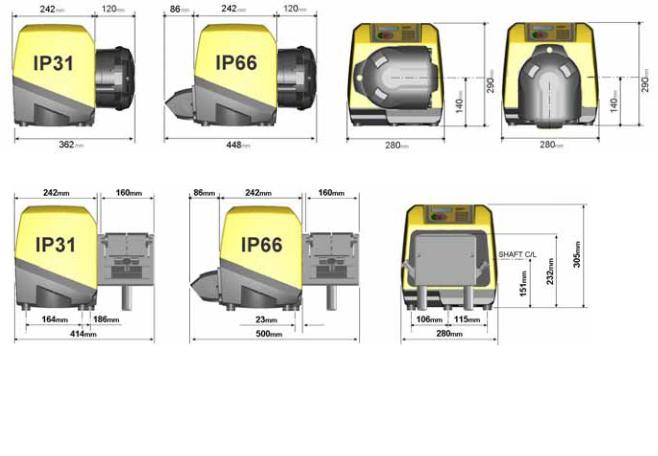
8.2 Dimensions
Unit weights
|
Drive only |
+ 620R, 620RE |
+ 620RE4 |
IP31 |
16.5kg, 36lb 6oz |
19.6kg, 43lb 3oz |
20.1kg, 44lb 5oz |
|
|
|
|
IP66 NEMA 4X |
17.4kg, 38lb 6oz |
20.5kg, 45lb 3oz |
21.0kg, 46lb 5oz |
|
|
|
|
Watson-Marlow 620UN, 620U, 620SN, 620S User Manual |
15 |

UN, U, SN, S 9 Good pump installation practice
9.1 General recommendations
Position
A correctly engineered installation will promote long tube life. Site the pump on a flat, horizontal, rigid surface, free from excessive vibration, to ensure correct lubrication of the gearbox. Allow a flow of air around the pump to ensure that heat can be dissipated. Ensure that the temperature around the pump does not exceed 40C.
Do not stack other 620 pumps on top of this pump. It is, however, acceptable to stack other equipment on the upper surface of the 620 (as long as the ambient temperature does not exceed 40C).
Emergency disconnection
The pump’s mains plug is the disconnecting device (for isolating the motor drive from the mains supply in an emergency). Do not position the pump so that it is difficult to disconnect the mains plug. The STOP key on the keypad will always stop the pump. However, it is recommended that a suitable local emergency stop device is fitted into the mains supply to the pump.
Valves
Peristaltic pumps are self-priming and self-sealing against backflow. No valves are required in inlet or discharge lines. Valves in the process flow must be opened before the pump operates. Users are advised to fit a pressure relief device between the pump and any valve on the discharge side of the pump to protect against damage caused by accidental operation with the discharge valve closed.
The pump may be set up so that the direction of rotor rotation is clockwise or count- er-clockwise, whichever is convenient.
Tubing materials: run-in advice
Sta-Pure, Chem-Sure and Marprene TM tubing are hard to compress when new. When using tubing made of these materials, the first five pumphead revolutions should be at a speed of 10rpm or greater. If the pump is run slower, the safety system built into pump drive’s software may cause it to stop and display an overcurrent error message.
Pressure advice
In most circumstances, rotor and tube life are maximised if the pumphead is run slowly, particularly when pumping at high pressure. However, to maintain performance at pressures above 2 bar, avoid running the pumphead below 50rpm. If low-flow, high-pressure operation is necessary, switching to a smaller tube is recommended.
Watson-Marlow 620UN, 620U, 620SN, 620S User Manual |
16 |
9.2 Do’s and do not’s
Do not build a pump into a tight location without adequate airflow around the pump.
Do ensure that when the 620N watertight module is fitted the seals are intact and properly located. Ensure that the holes for cable glands are properly sealed to maintain the IP66 / NEMA 4X rating.
Do not strap the control and mains power cables together.
Do keep delivery and suction tubes as short and direct as possible - though ideally not shorter than 1m - and follow the straightest route. Use bends of large radius: at least four times the tubing diameter. Ensure that connecting pipework and fittings are suitably rated to handle the predicted pipeline pressure. Avoid pipe reducers and lengths of smaller bore tubing than the pumphead section, particularly in pipelines on the suction side. Any valves in the pipeline (not usually needed) must not restrict the flow. Any valves in the flow line must be open when the pump is running.
Do use suction and delivery pipes equal to or larger than the bore of the tube in the pumphead. When pumping viscous fluids use pipe runs with a bore several times larger than the pump tube.
Do ensure that on longer tube runs at least 1m of smooth bore flexible tubing is connected to the inlet and discharge port of the pumphead to help to minimize impulse losses and pulsation in the pipeline. This is especially important with viscous fluids and when connecting to rigid pipework.
Do site the pump at or just below the level of the fluid to be pumped if possible. This will ensure flooded suction and maximum pumping efficiency.
Do keep the pumphead track and all moving parts clean and free from contamination and debris.
Do run at slow speed when pumping viscous fluids (though see Pressure advice in 9.1 General recommendations). Flooded suction will enhance pumping performance in all cases, particularly for materials of a viscous nature.
Do recalibrate after changing pump tubes, fluid, or any connecting pipework. It is also recommended that the pump is recalibrated periodically to maintain accuracy.
IP66 / NEMA 4X models may be hosed down, but should not be immersed. Protect from prolonged UV exposure.
IP31 models may be wiped with a damp cloth, but should not be hosed or immersed. The front of IP31 models is further protected against light spillages onto the pump.
When using Marprene or Bioprene continuous tubing, do re-tension the tube after the first 30 minutes of running.
Tube selection: The chemical compatibility lists published in Watson-Marlow publications are guides. If in doubt about the compatibility of a tube material and the duty fluid, request a Watson-Marlow tube sample card for immersion trials.
Watson-Marlow 620UN, 620U, 620SN, 620S User Manual |
17 |
UN, U, SN, S 10 Connecting this product to a power supply
A well regulated electrical mains supply is required along with cable connections conforming to the best practice of noise immunity. It is not recommended to site these drives alongside “dirty” electrical mains supplies such as 3-phase contactors and inductive heaters without special attention being paid to unacceptable mains-borne noise.
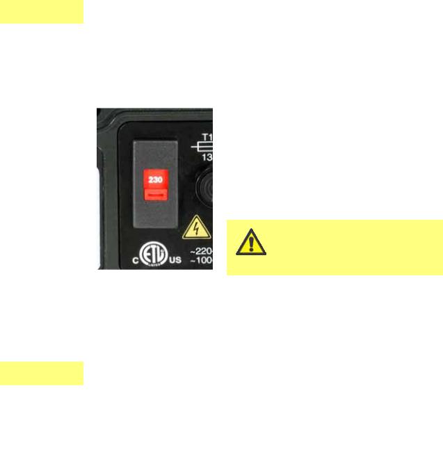
The voltage selector is mounted in the switchplate at the rear of the pump, protected from water by the 620N module (620DuN). The module must be removed to allow access to the switchplate. See 20.1
620N module removal and replacement. Set the voltage selector to 115V for 100-120V 50/60Hz supplies or 230V for 200-240V 50/60Hz supplies. Always check the voltage selector switch before connecting the mains supply. Make suitable connection to an earthed, single-phase mains electricity supply.
We recommend using commercially available supply voltage surge suppression where there
is excessive electrical noise.
Power cable: The pump is supplied fitted with either of two cable glands and approximately 2.8m of power cable. The European cable is to Harmonised code H05RN-F3G0.75, used with our gland part number SL0128 which is suitable for an outside cable sheath diameter of 4-7mm. The north American cable is to type SJTOW 105C 3-18AWG VW-1 used with our gland part number SL0123 which is suitable for an outside cable sheath diameter of 7-9mm.
Power cables of NEMA 4X specification pumps are fitted with a standard US mains UN, SN power plug. IP66 specification pumps are supplied with no plug. Wiring a mains plug
must only be undertaken by suitably skilled, qualified personnel.
Conductor coding
|
European |
North American |
line |
brown |
black |
neutral |
blue |
white |
ground |
green/yellow |
green |
|
|
|
Watson-Marlow 620UN, 620U, 620SN, 620S User Manual |
18 |

UN, SN |
|
The voltage selector switch is not visible while the |
|
|
620N module is in place. Do not switch the pump on |
|
||
|
|
unless you have checked that it is set to suit your |
|
|
power supply by removing the module and inspecting |
|
|
the switch, and then refitting the module. See 20.1 620N |
|
|
module removal and replacement. |
|
|
|
UN, U, SN, S
UN, U, SN, S
If the mains power cable is inappropriate for your installation, it can be changed. Please contact your local Watson-Marlow Bredel service centre.
Input line fusing: type T5A H 250V 20mm time-delayed cartridge fuse, located in a fuseholder in the centre of the switchplate at the rear of the pump.
Power interruption: This pump has an auto-restart feature which, when active, will restore the pump to the operating state it was in when power was lost. See 16.6 Auto-restart.
Stop / start power cycles: Do not power up/power down for more than 100 starts per hour, whether manually or by means of the auto-restart facility. We recommend remote control where a high number of starts is required.
11 Start-up check list
Note: See also 26.6 and 26.7 Tube loading.
Ensure that proper connections are achieved between the pump tube and suction and discharge piping.
Ensure proper connection has been made to a suitable power supply.
Ensure that the recommendations in section 9. Good pump installation practice are followed.
Watson-Marlow 620UN, 620U, 620SN, 620S User Manual |
19 |

UN, U, SN, S 12 Switching the pump on for the first time
Note: This manual uses bold type to highlight the active option in menu screens: “English” in the first screen represented here. The active option appears on the pump display in inverse text.
Switch on the power supply at the rear of the pump. The pump runs a poweron test to confirm proper functioning of the memory and hardware. If a fault is found, an error message is displayed. See 23.1 Error codes.
The pump displays a language menu. Use the UP and DOWN keys to select your language. Press the ENTER key to confirm your choice.
The information which follows assumes that your choice was English.
When the language is chosen this menu will not appear again and all menus will appear in the language you chose. (Language can be reset as described later. See 16.13 Language.)
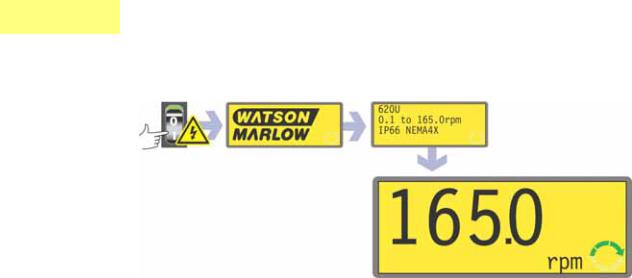
The pump displays the Watson-Marlow start-up screen for four seconds, followed by the pump model identity screen for four seconds (an example is shown here), and then the manual mode main screen.
The rotation symbol on the display indicates clockwise rotation. The default speed setting is 165rpm, but 265rpm is available (see 16.7 Set maximum allowed speed). Other initial start-up operational parameters are listed in the table below.
Watson-Marlow 620UN, 620U, 620SN, 620S User Manual |
20 |
UN, U
SN, S
UN, U, SN, S
620UN, 620U: First-time start-up defaults
Language |
Not set |
|
Analogue input |
4-20mA |
Speed |
165rpm |
|
User trim |
None |
Direction |
Clockwise |
|
Remote stop |
Open=run |
Pumphead |
620R |
|
Scrolling increment |
0.1rpm |
Tube size |
15.9mm |
|
Output 1 |
Run/Stop * |
Calibration |
620R 15.9mm tube |
|
Output 2 |
Direction † |
Backlight |
On |
|
Output 3 |
Auto/Man ‡ |
Keypad lock |
Off |
|
Output 4 |
General alarm |
Auto-restart |
Off |
|
|
|
Pump status |
Stopped |
|
|
|
|
|
|
|
|
Beeper |
On |
|
* Run |
= high |
Manual screen |
rpm |
|
† Clockwise rotation |
= high |
Security code |
Not set |
|
‡ Auto |
= high |
|
|
|
|
|
Note: The settings shown above for Run, Clockwise rotation and Auto are those in force on initial start-up for the functions available on Output 1, Output 2 and Output 3 respectively. For example, a high signal on Output 2 indicates clockwise rotation. These can be exchanged later according to user requirements.
Note: High is equivalent to the common and normally open contacts of the relay on the adapter board being closed.
620SN, 620S: First-time start-up defaults
Language |
Not set |
Keypad lock |
Off |
Speed |
165rpm |
Auto-restart |
Off |
Direction |
Clockwise |
Pump status |
Stopped |
Pumphead |
620R |
Beeper |
On |
Tube size |
15.9mm |
Manual screen |
rpm |
Calibration |
620R 15.9mm tube |
Scrolling increment |
0.1rpm |
Backlight |
On |
|
|
The pump is now ready to operate according to the defaults listed above.
All operating parameters may be changed by means of key-presses. See 14. Manual operation.
Watson-Marlow 620UN, 620U, 620SN, 620S User Manual |
21 |
UN, U, SN, S 13 Switching the pump on in subsequent power cycles (if not in auto-restart mode)
Switch on the power supply at the rear of the pump. The pump runs a poweron test to confirm proper functioning of the memory and hardware. If a fault is found, an error message is displayed. See 23.1 Error codes.
The pump displays the Watson-Marlow start-up screen for four seconds followed by the pump model identity screen for four seconds (an example is shown here), and then the manual mode main screen.
Note: Once in the manual mode main screen, keys assume their normal functions - see 15.1 Keypad in menu screens below. A subsequent press on START causes the pump to operate.
Start-up defaults are those in place when the pump was switched off last. Check that the pump is set to operate as you require it.
The pump is now ready to operate.
All operating parameters may be changed by means of key-presses. See 14. Manual operation below.
Watson-Marlow 620UN, 620U, 620SN, 620S User Manual |
22 |
14 Manual operation
UN, U 14.1 Keypad functions, 620UN, 620U
All settings and functions of the pump in manual mode are set and controlled by means of key-press- es. Immediately after the start-up display sequence detailed above, the manual mode main screen will be displayed. The currently selected rotation direction is indicated on the display by a clockwise or count- er-clockwise segmented arrow. If an exclamation mark ( ! ) shows, it indicates that Auto-restart is on. If a padlock icon (  ) shows, it indicates that Keypad lock is on.
Note: A number of the controls
listed below are shortcuts to commands which are also available through the Main menu. See 15 Main menu.
A brief single press on each key triggers a beep sound (if enabled - see 14.6 Keypad beep) and causes the pump to function as follows:
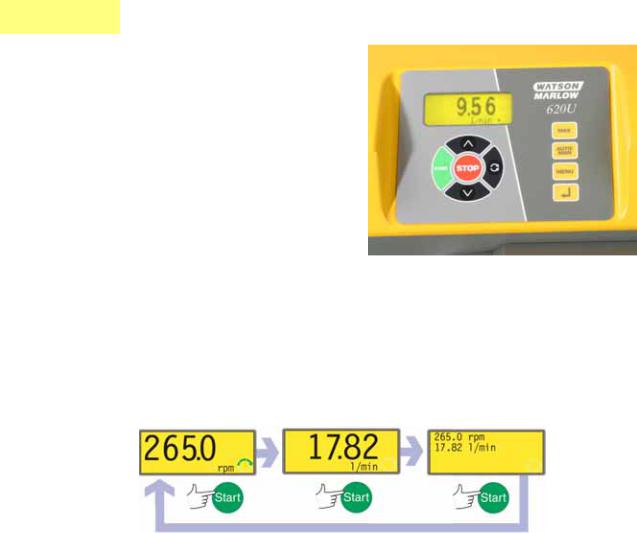
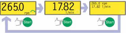
START: starts the pump at the speed and in the direction shown on the display. The rotation symbol will become animated to confirm that the pump is operating.
If the pump is running when START is pressed, it causes the information shown on the manual mode main screen to cycle from revolutions per minute, to flowrate in a choice of units (via a warning screen if flowrate has not been calibrated and if this is the first cycle since power-up) to rpm, flowrate and Run time. An example is shown here. The default can be altered from within the Setup menu (see 16.3 Display).
Watson-Marlow 620UN, 620U, 620SN, 620S User Manual |
23 |
MAX: while pressed, MAX operates the pump at the maximum allowed speed and in the direction shown on the display. When released, the pump returns to its previous status.
Note: Priming can be achieved by pressing the MAX key until fluid flows through the pump and reaches the point of discharge, and then releasing the MAX key.
AUTO/MAN: toggles the pump into analogue control. When started, the pump runs at the speed set by any analogue signal applied to the pump, and in the direction shown in the display.
STOP: if the pump is running, pressing STOP stops the pump. The display will continue to show the previous speed and direction. The pump will return to this speed and direction when the START key is pressed again.
UP: increases the speed shown on the display in minimum steps of 0.1rpm, or other steps as pre-selected in the Scrolling section of the Setup menu, (unless the speed displayed is already the maximum allowed speed). If the pump is then started by pressing the START key, it will operate at the new speed. If the pump is running when UP in pressed, the change takes effect immediately. Note: If the pump’s flow rate has been calibrated (see 17.3 Calibration), after a speed change a screen showing the new rpm figure and the new flowrate is displayed for four seconds before returning the user to the previously set manual mode main screen: rpm or flowrate.
DOWN: decreases the speed shown on the display in minimum steps of 0.1rpm, or other steps as pre-selected in the Scrolling section of the Setup menu. If the pump is then started by pressing the START key, it operates at the new speed. The minimum speed possible is 0.1rpm. If the pump is running when DOWN is pressed, the change takes effect immediately.
Note: If the pump’s flow rate has been calibrated (see 17.3 Calibration), after a speed change a screen showing the new rpm figure and the new flowrate is displayed for four seconds before returning the user to the previously set manual mode main screen: rpm or flowrate.
Note: You can reduce the pump speed from 0.1rpm (or any other minimum displayed unit of speed as selected in the Scrolling section of the Setup menu) to 0rpm by a further press on the DOWN key. The pump is still in the running state and the rotation symbol will continue to move. Press the UP key to return the pump to the minimum speed.
Note: If a minimum allowed speed has been set in the Set Min Speed section of the Setup menu, the above note on speed reduction to 0rpm does not apply.
DIRECTION: toggles the direction of rotation shown on the display. If the pump is then started by pressing the START key, it rotates in the new direction. If the pump is running when DIRECTION is pressed, the change takes effect immediately.
ENTER: is used to enter/confirm numeric and menu selections. Also cycles the information shown on the manual mode main screen exactly as START does, whether the pump is running or not. See START, above.
MENU: causes the main menu to be displayed, from which all aspects of pump setup can be controlled, including the MemoDose facility. See 15. Main menu.
Watson-Marlow 620UN, 620U, 620SN, 620S User Manual |
24 |

Keypress combinations cause the pump to function as follows:
Note: A number of the controls listed below are shortcuts to commands which are also available through the Main menu. See 15. Main menu.
UP and DIRECTION on power-up: toggles the keypad beep on and off.
START on power-up: switches on the Auto-restart facility. See 16.6 Autorestart.
STOP on power-up: switches off the Auto-restart facility. See 16.6 Autorestart.
STOP and DIRECTION on power-up: allows the user to press UP and DOWN keys to toggle the sense of remote run/stop control between open=stop and open=run.
STOP and UP while the pump is stopped: turns the display backlight on.
STOP and DOWN while the pump is stopped: turns the display backlight off.
MAX and UP: sets the pump to maximum allowed speed.
MAX and DOWN: sets the pump to minimum allowed speed.
DIRECTION and DOWN: interrupts the display to show the pump’s ROM version for four seconds.
START pressed and held for two seconds: toggles the keypad lock on and off. Only the START and STOP keys are active when keypad lock is on. The padlock icon is displayed.
STOP pressed and held for two seconds: toggles the keypad lock on and off. Only the START and STOP keys are active when keypad lock is on. The padlock icon is displayed.
STOP STOP within half a second: shortcut entry to the MemoDose menu; when in MemoDose, shortcut return to manual mode main screen. See 17.
MemoDose.
SN, S 14.2 Keypad functions, 620SN, 620S
All settings and functions of the pump in manual mode are set and controlled by means of key-press- es. Immediately after the start-up display sequence detailed above, the manual mode main screen will be displayed. The currently selected rotation direction is indicated on the display by a clockwise or count- er-clockwise segmented arrow. If an exclamation mark ( ! ) shows, it indicates that Auto-restart is on. If a padlock icon (  ) shows, it indicates that Keypad lock is on.
A brief single press on each key
triggers a beep sound (if enabled - see 14.6 Keypad beep) and causes the pump to function as follows:
Watson-Marlow 620UN, 620U, 620SN, 620S User Manual |
25 |
START: starts the pump at the speed and in the direction shown on the display. The rotation symbol will become animated to confirm that the pump is operating.
If the pump is running when START is pressed, it causes the information shown on the manual mode main screen to cycle from revolutions per minute, to flowrate in millilitres per minute (via a warning screen if flowrate has not been calibrated and if this is the first cycle since power-up) to rpm and flowrate. An example is shown here.
MAX: while pressed, MAX operates the pump at the maximum allowed speed and in the direction shown on the display. When released, the pump returns to its previous status.
Note: Priming can be achieved by pressing the MAX key until fluid flows through the pump and reaches the point of discharge, and then releasing the MAX key.
STOP: if the pump is running, pressing STOP stops the pump. The display will continue to show the previous speed and direction. The pump will return to this speed and direction when the START key is pressed again.
STOP is also used in the MemoDose facility, while calibrating the pump, and setting the maximum speed.
UP: increases the speed shown on the display in minimum steps of 0.1rpm, or other steps as pre-selected in the Scrolling section of the Setup menu, (unless the speed displayed is already the maximum allowed speed). If the pump is then started by pressing the START key, it will operate at the new speed. If the pump is running when UP in pressed, the change takes effect immediately. Note: If the pump’s flow rate has been calibrated (see 17.3 Calibration), after a speed change a screen showing the new rpm figure and the new flowrate is displayed for four seconds before returning the user to the previously set manual mode main screen: rpm or flowrate.
DOWN: decreases the speed shown on the display in minimum steps of 0.1rpm, or other steps as pre-selected in the Scrolling section of the Setup menu. If the pump is then started by pressing the START key, it operates at the new speed. The minimum speed possible is 0.1rpm. If the pump is running when DOWN is pressed, the change takes effect immediately.
Note: If the pump’s flow rate has been calibrated (see 17.3 Calibration), after a speed change a screen showing the new rpm figure and the new flowrate is displayed for four seconds before returning the user to the previously set manual mode main screen: rpm or flowrate.
Note: You can reduce the pump speed from 0.1rpm (or any other minimum displayed unit of speed as selected in the Scrolling section of the Setup menu) to 0rpm by a further press on the DOWN key. The pump is still in the running state and the rotation symbol will continue to move. Press the UP key to return the pump to the minimum speed.
Note: If a minimum allowed speed has been set in the Set Min Speed section of the Setup menu, the above note on speed reduction to 0rpm does not apply.
Watson-Marlow 620UN, 620U, 620SN, 620S User Manual |
26 |
DIRECTION: toggles the direction of rotation shown on the display. If the pump is then started by pressing the START key, it rotates in the new direction. If the pump is running when DIRECTION is pressed, the change takes effect immediately.
ENTER: is used to enter/confirm numeric and menu selections. Also cycles the information shown on the manual mode main screen exactly as START does, whether the pump is running or not. See START, above.
MENU: causes the main menu to be displayed, from which pump Setup and MemoDose can be controlled. See 15. Main menu.
MEMODOSE: causes the MemoDose facility to be displayed. See 17.
MemoDose.
Keypress combinations cause the pump to function as follows:
DIRECTION on power-up: resets defaults.
UP and DIRECTION on power-up: toggles the keypad beep on and off.
START on power-up: switches on the Auto-restart facility. See 16.6 Autorestart.
STOP on power-up: switches off the Auto-restart facility. See 16.6 Autorestart.
STOP and UP while the pump is stopped: turns the display backlight on.
STOP and DOWN while the pump is stopped: turns the display backlight off.
DIRECTION and DOWN: interrupts the display to show the pump’s ROM version for four seconds.
MAX and UP: sets the pump to maximum allowed speed.
MAX and DOWN: sets the pump to minimum allowed speed.
START pressed and held for two seconds: toggles the keypad lock on and off. Only the START and STOP keys are active when keypad lock is on. The padlock icon is displayed.
STOP pressed and held for two seconds: toggles the keypad lock on and off. Only the START and STOP keys are active when keypad lock is on. The padlock icon is displayed.
STOP STOP within half a second: shortcut entry to the MemoDose menu; when in MemoDose, shortcut return to manual mode main screen. See 17.
MemoDose.
Watson-Marlow 620UN, 620U, 620SN, 620S User Manual |
27 |

UN, U, SN, S 14.3 Speed
To change the running speed:
Use the UP and DOWN keys to change the pump’s running speed within limits of the minimum allowed speed and the maximum allowed speed. The minimum speed possible is 0.1rpm.
Note: You can reduce the pump speed from 0.1 rpm to 0 rpm by a further press on the DOWN key. The pump is still in the running state and the rotation symbol will continue to move. Press the UP key to return the pump to the minimum speed.
Note: The maximum allowed speed of the drive defaults to 165rpm. It is possible to set this limit at any speed up to 265rpm. See 16.7 Set maximum allowed speed, and section 3 Five-year warranty.
14.4 Direction
To toggle the pump’s rotation sense:
Press DIRECTION to toggle the pump between clockwise and counter-clock- wise rotation.
Note: Direction control is available subject to access not being limited by security code. See 16.15 Security code.
14.5 Keypad lock
The keypad can be locked to prevent changes to pump speed or other settings, and make it possible only to start or stop the pump. The padlock symbol shows on the display.
While the pump is running, hold down the START key for two seconds. The padlock symbol shows and only the START and STOP keys function.
The keypad may also be locked while the pump is stopped. Hold down the STOP key for two seconds. The padlock symbol shows and only the START and STOP keys function.
To unlock the keypad while the pump is running hold down the START key for two seconds. The padlock symbol is removed. If the pump is stopped hold down the STOP key until the padlock symbol is removed.
Note: Keypad lock is available subject to access not being limited by security code. See 16.15 Security code.
14.6 Keypad beep
The pump keypad can operate silently or indicate a positive key-press with a beep sound.
To toggle the sound on and off, stop the pump. Turn off the mains power switch at the rear of the pump.
Depress the UP and DIRECTION keys while switching on the mains power switch at the rear of the pump.
Watson-Marlow 620UN, 620U, 620SN, 620S User Manual |
28 |

14.7 To reset defaults
All settings can be re-set to factory defaults.
Turn off the mains power switch at the rear of the pump.
Press the DIRECTION key while switching on the mains power switch at the rear of the pump. A warning screen is displayed briefly, followed by a screen asking the user to confirm that factory defaults are to be reset.
Select Yes or No using the UP and DOWN keys. Confirm by pressing ENTER. If Yes was confirmed, the pump resets all user-settable data to default values and displays the manual mode main screen. If No was confirmed, no change is made and the manual mode main screen is displayed.
The language of display screens may be reset only by resetting defaults.
14.8 To reset language
The language of display screens is set on initial start-up. To reset language, reset all defaults (see 14.7 To reset defaults).
14.9 Backlight
To turn the display backlight on:
Depress the STOP and UP keys together.
To turn the display backlight off:
Depress the STOP and DOWN keys together.
See 16.11 Backlight.
14.10 Auto-restart
This pump offers an auto-restart feature. When active on power loss, it will restore the pump when power returns to the operating state it was in when power was lost. It does not operate when powering down in the middle of a dose; when the pump is restarted, it will await a press on the START key to begin the interrupted dose again. Auto-restart is retained while the pump is switched off. When the pump starts running look for the ! symbol on the display. This ! symbol indicates that the pump is set for auto-restart.
Do not use auto-restart for more than 100 starts per hour. We recommend remote control where a high number of starts is required.
Watson-Marlow 620UN, 620U, 620SN, 620S User Manual |
29 |
To turn the auto-restart facility on:
Turn off the mains power switch at the rear of the pump.
Depress the START key while switching on the mains power switch at the rear of the pump.
To turn the auto-restart facility off:
Turn off the mains power switch at the rear of the pump.
Depress the STOP key while switching on the mains power switch at the rear of the pump.
|
14.11 Manual operation and remote |
|
UN, U |
||
digital inputs and outputs |
||
|
||
|
||
|
The remote run / stop, direction and leak-detected inputs are operational. |
|
|
The remote status outputs are all fully functional. |
|
|
The STOP key acts as an overriding emergency stop. The run / stop input will not |
|
|
start the pump in manual mode, but once the START key has been pressed, the |
|
|
remote run / stop input will stop and start the pump according to its operational |
|
|
state. |
|
|
(620UN) If you invert the operation of the remote run / stop switch to operate as |
|
|
open=stop, you must connect pin 7 to 19, lower D-connector, to be able to start |
|
|
the pump from the keypad. See 20.6 Run/stop injput. |
|
|
(620U) If you invert the operation of the remote run / stop switch to operate as |
|
|
open=stop, you must connect pin 7 to 19, lower D-connector, to be able to start |
|
|
the pump from the keypad. See 20.6 Run/stop injput. |
|
|
If STOP is pressed the remote run / stop switch will have no effect. |
|
|
You cannot invert the remote direction signal. |
Watson-Marlow 620UN, 620U, 620SN, 620S User Manual |
30 |
 Loading...