


313F, 313S, 313U, 313T
313fstu-gb-03.pdf

Declarations
Declaration of |
When this pump unit is used as a stand alone pump it complies with: Machinery Directive |
||
conformity |
98/37/EC EN60204-1, Low Voltage Directive 73/23/EEC EN61010-1, EMC Directive |
||
|
|
|
89/336/EEC, EN50081-1/EN50082-1. |
|
|
|
|
|
|
||
|
|
||
Declaration of |
When this pump unit is to be installed into a machine or is to be assembled with other |
||
Incorporation |
machines for installations, it must not be put into service until the relevant machinery has |
||
|
|
|
been declared in conformity with the Machinery Directive 98/37/EC EN60204-1. |
Responsible person: Dr R Woods, Managing Director, Watson-Marlow Limited, Falmouth, Cornwall TR11 4RU, England. Telephone 01326 370370 Fax 01326 376009.
Two year warranty
Watson-Marlow Limited warrants, subject to the conditions below, through either Watson-Marlow Limited, its subsidiaries, or its authorised distributors, to repair or replace free of charge, including labour, any part of this product which fails within two years of delivery of the product to the end user. Such failure must have occurred because of defect in material or workmanship and not as a result of operation of the product other than in accordance with the instructions given in this manual.
Conditions of and specific exceptions to the above warranty are:
∙Consumable items such as tubing, rollers and brushes are excluded.
∙Products must be returned by pre-arrangement carriage paid to Watson-Marlow Limited, its subsidiaries, or its authorised distributor.
∙All repairs or modifications must have been made by Watson-Marlow Limited, its subsidiaries, or its authorised distributors or with the express permission of Watson-Marlow Limited, its subsidiaries, or its authorised distributors.
∙Products which have been abused, misused, or subjected to malicious or accidental damage or electrical surge are excluded.
Warranties purporting to be on behalf of Watson-Marlow Limited made by any person, including representatives of Watson-Marlow Limited, its subsidiaries, or its distributors, which do not accord with the terms of this warranty shall not be binding upon Watson-Marlow Limited unless expressly approved in writing by a Director or Manager of Watson-Marlow Limited.
Information for returning pumps
Equipment which has been contaminated with, or exposed to, body fluids, toxic chemicals or any other substance hazardous to health must be decontaminated before it is returned to Watson-Marlow or its distributor.
A certificate included at the rear of these operating instructions, or signed statement, must be attached to the outside of the shipping carton.
This certificate is required even if the pump is unused. If the pump has been used, the fluids that have been in contact with the pump and the cleaning procedure must be specified along with a statement that the equipment has been decontaminated.
Safety
In the interests of safety, this pump and the tubing selected should only be used by competent, suitably trained personnel after they have read and understood this manual, and considered any hazard involved.
Any person who is involved in the installation or maintenance of this equipment should be fully competent to carry out the work. In the UK this person should also be familiar with the Health and Safety at Work Act 1974.
There are dangerous voltages (at mains potential) inside the pump. If access is required, isolate the pump from the mains before removing the cover.
Recommended operating procedures
DO keep delivery and suction lines as short as possible using a minimum number of swept bends.
DO use suction and delivery pipelines with a bore equal to or larger than the bore of the tube fitted in the pumphead. When pumping viscous fluids, the losses caused by increased friction can be overcome by using pipe runs with a cross sectional area several times greater than the pumping element.
DO fit an extra length of pump tube in the system to enable tube transfer. This will extend tube life and minimise the downtime of the pumping circuit.
DO keep the track and rollers clean.
The self-priming nature of peristaltic pumps means valves are not required Any valves fitted must cause no restriction to flow in the pumping circuit.
When using Marprene tubing, after the first 30 minutes of running, re-tension the tube in the pumphead by releasing the tube clamp on the delivery side a little and pulling the tube tight. This is to counteract the normal stretching that occurs with Marprene which can go unnoticed and result in poor tube life.
Tube selection The chemical compatibility list published in the Watson-Marlow catalogue is only a guide. If in doubt about the compatibility of a tube material and the duty fluid, request a tube sample card for immersion trials.
Installation
The 313F, 313S and 313U are suitable for single phase mains electricity supplies only.
To ensure correct lubrication of the gearbox the pump should be run only while its feet are standing on a horizontal surface. The pump should be positioned to allow a free flow of air around it.
Set the voltage selector to either 120V for 100-120V 50/60Hz supplies or 240V for 220-240V 50/60Hz supplies.
A mains cable fitted with a moulded plug is supplied with the pump. The wires are colour coded in accordance with the following code:
∙220-240V: Live - Brown; Neutral - Blue; Earth - Green/Yellow.
∙100-120V: Live - Black; Neutral - White; Earth - Green.
Troubleshooting
Should the pump fail to operate, make the following checks to determine whether or not servicing is required.
∙Check that the power switch is on.
∙Check the mains supply is available at the pump.
∙Check the voltage selector switch is in the correct position. l
∙Check the fuse in the mains socket.
∙Check that the pump is not stalled by incorrect fitting of tubing.
313F/D manual operation
∙Set the voltage selector to either 120V for 100-120V 50/60Hz single phase AC supplies or 240V for 220-240V 50/60Hz single phase AC supplies.
∙Set the pump to the desired high or low speed setting using the horizontal slider switch on the rear panel.
∙Stop Stop the pump by turning the Forward/Off/Reverse switch to its central Off position.
313S/D, 313U/D manual operation
∙Set the voltage selector to either 120V for 100-120V 50/60Hz single phase AC supplies or 240V for 220-240V 50/60Hz single phase AC supplies.
∙Set the pump to the desired speed output using the front panel potentiometer.
∙Turn the pump on using the mains power switch on the rear panel.
∙Start up direction Start the pump by turning the Forward/Off/Reverse switch to the required direction of rotation.
∙Stop Stop the pump by turning the Forward/Off/Reverse switch to its central Off position.
Note: When the pump is running clockwise in manual operation and is switched to standby, it will come to a dead stop. When running counter clockwise it will freewheel to a stop. Any application requiring braking should have the pump set up for clockwise running.
3
313U automatic operation
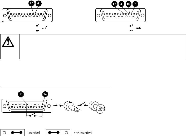
For the pump to be controlled by a process signal, the auto volts/manual/auto current (V M I) slider switch on the rear panel should be set to either auto volts or auto current depending upon the type of control signal to be used. Ensure that the mains switch on the rear panel is off. The process signal must be connected to the 25-way Dee plug provided, which must be inserted in the rear panel 25-way Dee connector. The pump is controllable by an analogue process signal of up to 0 to 10V or 4 to 20mA. The pump will provide an increasing flow rate for rising control signal (non-inverted response ).
Voltage signal |
Current signal |
|
|
||||||||||||||||||||||||||||
Input impedance 220 kohms. |
Maximum Input impedance 250 ohms |
|
|
||||||||||||||||||||||||||||
voltage signal 10V |
|
|
|
|
|
|
|
|
|
|
|
|
|
|
|
|
|
||||||||||||||
|
|
|
|
|
|
|
|
|
|
|
|
|
|
|
|
|
|
|
|
|
|
|
|
|
|
|
|
|
|
|
|
|
|
|
|
|
|
|
|
|
|
|
|
|
|
|
|
|
|
|
|
|
|
|
|
|
|
|
|
|
|
|
|
|
|
|
|
|
|
|
|
|
|
|
|
|
|
|
|
|
|
|
|
|
|
|
|
|
|
|
|
|
|
|
|
|
|
|
|
|
|
|
|
|
|
|
|
|
|
|
|
|
|
|
|
|
|
|
|
|
|
|
|
|
|
|
|
|
|
|
|
|
|
|
|
|
|
|
|
|
|
|
|
|
|
|
|
|
|
|
|
|
|
|
|
|
|
|
|
|
|
|
|
|
|
|
|
|
|
|
|
|
|
|
|
|
|
|
|
|
|
|
|
|
|
|
|
|
|
|
|
|
|
|
|
|
|
|
|
|
|
|
|
|
|
|
|
|
|
|
|
|
|
|
|
|
|
|
|
|
|
|
|
|
|
|
|
|
|
|
|
|
|
|
|
|
|
|
|
|
|
|
|
|
|
|
|
|
|
|
|
|
|
|
|
|
|
|
|
|
|
|
|
|
|
|
|
|
|
|
|
|
|
|
|
|
|
|
|
|
|
|
|
|
|
|
|
|
|
|
|
|
|
|
|
|
|
|
|
|
|
|
|
|
|
|
|
|
|
|
|
|
|
|
|
|
|
|
|
|
|
|
|
|
|
|
|
|
|
|
|
|
|
|
|
|
|
|
|
|
|
|
|
|
|
|
|
|
|
|
|
Never apply mains voltage across any pins on the 25D socket. Up to 10V may be applied across pins 4 and 17, but no voltage should be applied across other pins. Permanent damage, not covered by warranty may result in both instances. Do not use the mains power switch to control the pump for a high repetition of stop/starts. The auto-control facility should be used.
When setting the drive control mode with the V M I switch ensure that power to the drive is switched off using the mains switch on the rear panel.
Remote control
Stop/Start
Connect remote switch between pins 7 and 14 of the 25 pin socket. Close contact to stop the pump, open to run. With no connection, the pump will default to running. A remote stop/start signal will control the pump whilst running under manual operation.
A TTL compatible logic input (Low 0V High 5V ) may be applied to pin 7.
To invert the response to the signal input move the remote stop signal inverter link (see 313 "U" upgrade card, item 4, LK2) to the inverted pin positions on the signal inverter link block.
Note: When the pump is running in either direction and is stopped remotely, it will freewheel to a stop.
4

Direction
The remote direction facility operates with the front panel direction switch set in the anti-clockwise direction only. Connect remote switch between pins 5 and 16. Open switch for anti-clockwise rotation, close for clockwise rotation. With no connection, the pump will default to anti-clockwise
To invert the response to the signal input move the remote direction signal inverter link LK1 (see 313 "U" upgrade card, item 6, LK1) to the inverted pin positions on the signal inverter link block.
Note: When the front panel switch is set to CCW rotation, the drive rotates according to the remote switch direction set by LK1. When the front panel switch is set to CW rotation the remote switch is inhibited.
Speed
A remote potentiometer with a nominal value of between 1K and 2K with a minimum of 0.25W should be wired as shown. When using a remote potentiometer, do not apply a voltage/current control input signal at the same time. Set the drive control mode to auto volts (0-10V). Ensure that when changing the drive control mode, power to the drive is switched off using the rear panel mains switch.
Note: As the remote potentiometer utilises the 0-10V range the speed response is only over 10/12ths of the potentiometer's electrical travel. The signal overload illuminates at this point and there is no further increase in speed.
313U upgrade card
To upgrade the manually controllable 313S/D into a remote or 0-10V/4-20mA analogue controllable 313U/D a 313U upgrade card will be required (part number 039.3001.U00). To install the "U" card, undo the four M3 screws on the drive rear panel "S" version cover plate and remove. Slot the 313U upgrade card into the rear panel recess, drop down to align the DIN edge connectors and push into position. Replace the four M3 screws on the card to secure it firmly to the rear panel.
5
 Loading...