


INSTRUCTION HANDBOOK
PD12I / PD12P
INSTRUCTION HANDBOOK
PD12I PD12P
(foto examples; exact model may vary)
PD12IP IH 1.03 EN |
Version: 1.03 |
Page 1 of 20 |
|
|
|

INSTRUCTION HANDBOOK
PD12I / PD12P
TABLE OF CONTENTS |
|
|
1 |
PD12 I / PD12 P important notice ........................................................................................... |
3 |
2 |
Caution ................................................................................................................................... |
4 |
3 |
General information ................................................................................................................ |
5 |
3.1 |
Unpacking and inspection....................................................................................................... |
5 |
3.2 |
The peristaltic principle ........................................................................................................... |
5 |
3.3 |
Installation .............................................................................................................................. |
6 |
3.3.1 |
PD12I Installation.................................................................................................................... |
6 |
3.3.2 |
PD12P Installation .................................................................................................................. |
7 |
3.4 |
Addressing of filling station ..................................................................................................... |
8 |
4 |
Control.................................................................................................................................... |
9 |
4.1 |
Dispenser head....................................................................................................................... |
9 |
5 |
Dispensing with PD12........................................................................................................... |
10 |
5.1 |
Vessel Placement ................................................................................................................. |
10 |
5.2 |
Tube size .............................................................................................................................. |
11 |
5.3 |
Nature of fill media................................................................................................................ |
12 |
5.4 |
Priming tubes........................................................................................................................ |
12 |
5.5 |
Drip....................................................................................................................................... |
12 |
5.6 |
Hard Feed............................................................................................................................. |
12 |
6 |
Tube assembly ..................................................................................................................... |
13 |
6.1 |
Assembly of Y-connectors .................................................................................................... |
13 |
6.2 |
Placing tubes in the pump head............................................................................................ |
13 |
7 |
Programming ........................................................................................................................ |
15 |
7.1 |
Programming principle .......................................................................................................... |
15 |
7.2 |
PD12 parameters.................................................................................................................. |
15 |
8 |
Cleaning and maintenance ................................................................................................... |
16 |
8.1 |
Daily cleaning ....................................................................................................................... |
16 |
8.2 |
Sterilization ........................................................................................................................... |
16 |
8.3 |
Maintenance ......................................................................................................................... |
16 |
9 |
Interface and change of voltage............................................................................................ |
17 |
9.1 |
PD12 I Interface.................................................................................................................... |
17 |
9.2 |
PD12 P Interface .................................................................................................................. |
18 |
9.3 |
Connecting multiple PD12P’s to Flexnet ............................................................................... |
19 |
9.4 |
Change of voltage................................................................................................................. |
19 |
10 |
Declaration of conformity ...................................................................................................... |
20 |
PD12IP IH 1.03 EN |
Version: 1.03 |
Page 2 of 20 |
|
|
|

INSTRUCTION HANDBOOK
PD12I / PD12P
1 PD12 I / PD12 P important notice
There are 2 versions of the PD12.
The PD12 I (individual)
The PD12 P (Panelmount)
They share the same functions and programming routines.
The main difference is that the PD12 I has its own cabinet, and the PD12 P is mounted through a panel.
Besides this there are differences in the way the “I” and “P” version are connected to power supply and to the external pump controller (MC12).
In the last sections of the manual we will describe the connections and interfaces. For the remainder of this manual the PD12 will be designated as follows:
PD12: for general descriptions covering both versions.
PD12 I: for descriptions specific to the ”I” version.
PD12 P: for descriptions specific to the ”P” version.
PD12IP IH 1.03 EN |
Version: 1.03 |
Page 3 of 20 |
|
|
|

INSTRUCTION HANDBOOK
PD12I / PD12P
2 Caution
This manual should be read before using the PD12.
Explanations to the pictograms:
Warning against touching/Warning against opening:
Warning against high voltage:
When operating the PD12, make sure that the dispenser head is closed.
The mains switch is used for emergency stopping.
The PD12 should only be used for dosing and filling of liquid fluids.
The PD12 must be placed on a stable bed plate and in such a way, that it is not exposed to great humidity, high temperatures or other abnormal operating-environments. It is not to be used in explosion hazardous environments.
It is prohibited to maintain or clean the PD12, when it is connected to the power supply.
It is prohibited for unauthorised personnel to open the cover of the PD12's electrical parts.
Always remember that the PD12 must be earthed by way of the switch.
The pump must not run dry.
PD12IP IH 1.03 EN |
Version: 1.03 |
Page 4 of 20 |
|
|
|

INSTRUCTION HANDBOOK
PD12I / PD12P
3 General information
3.1Unpacking and inspection
PD12 is a peristaltic filler in the Flexicon Multi Filling System (FMFS). The PD12 can not do fillings by itself, but must be connected to Flexicons control unit, the MC12.
Please check that all ordered items have been received and that no items were damaged during transport. In case of any defects or omissions, please contact WM Flexicon A/S or your supplier immediately.
When ordering spare parts or accessories for the PD12, please state the serial number stamped. The serial number is stamped on the label on the bottom of the PD12.
ALWAYS REMEMBER that this machine must be earthed.
3.2The peristaltic principle
PD12 operates with a peristaltic dispenser head (tube pump), where the liquid only comes into contact with the flexible tube, the tube connections and the filling needle. The tubes are usually made of silicone, but other materials can also be used.
The dispenser head is designed in such a way that sterilized tubes can be mounted in the head without affecting the sterility. WM Flexicons tubes fullfills biopharma requirements. The tubes are delivered in sealed packages and are provided with a batch number which makes it possible to trace the tubes all the way back to the raw material source.
For this reason the PD12 is specially suited for aseptic applications and for preventing crosscontamination among different products.
The dispenser head is self-priming, and the dispenser head itself can stand to be run dry. It is recommended not to let the dispenser head be run dry for a long period WITH MOUNTED
TUBES, since this will lead to particle release.
A peristaltic dispenser head is not suitable for viscous products.
PD12IP IH 1.03 EN |
Version: 1.03 |
Page 5 of 20 |
|
|
|
INSTRUCTION HANDBOOK
PD12I / PD12P
3.3Installation
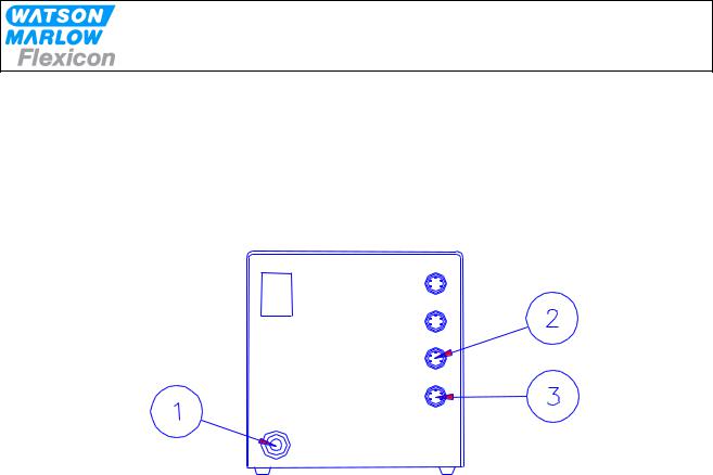
3.3.1 PD12I Installation
PD12I must be placed on a stable bedplate, and all electrical connections are on its rear.
Fig. 3.1
The cable with plug (1) is connected to an earthed switch.
The communication cable from MC12 (type 3) comes fitted with two 4-pin DIN plugs. One is connected to the "net 1" socket (2) on the PD12I, and the other plug is connected to the "net" socket on MC12.
The terminator supplied with MC12 (4-pin blind DIN plug) is connected to the "net 2" (3) socket on PD12I.
Should the system be operating more than one PD12I, the "net 2" socket (3) is to be connected to the "net 1" socket (2) on the next PD12I by a communication cable (type 3). The terminator is connected to the last PD12I on the line.
Address "1" is the factory setting of PD12I. In case you want to change this setting, please consult section 3.4 in this manual.
PD12I is now ready to be switched on and to be programmed from the MC12.
PD12IP IH 1.03 EN |
Version: 1.03 |
Page 6 of 20 |
|
|
|
 Loading...