


MC12

OPERATORS AND
REFERENCE MANUAL
MC12
MC12 OM RM 1.03_EN Version: 1.03 Date: 2010-11-17 Page 1 of 46
Operators and Reference
M anual
MC12

Operators and Reference Manual
MC12
MC12 OM RM 1.03_EN Version: 1.03 Date: 2010-11-17 Page 2 of 46
1. DECLARATION OF CONFORMITY .............................................................................. 5
2. ABOUT THIS MANUAL................................................................................................... 6
3. MC12 SYSTEM DESIGN ................................................................................................ 6
3.1 RS485 MULTIDROP NETWORK............................................................................................. 6
4. GENERAL INFORMATION............................................................................................. 7
4.1 UNPACKING AND INSPECT ION .............................................................................................. 7
4.2 CONNECTIONS MC12P....................................................................................................... 7
4.3 CONNECTIONS MC12 TABLE TOP MODEL ............................................................................. 7
5. CONTROL ....................................................................................................................... 8
5.1 DISPLAY ............................................................................................................................. 8
5.2 KEYPAD .............................................................................................................................. 9
6. PROGRAMMING........................................................................................................... 10
6.1 STARTING THE MC12 ........................................................................................................ 10
6.2 PASSWORD PROTECTION.................................................................................................. 10
6.3 PARAMETERS.................................................................................................................... 11
6.4 PROGRAMS....................................................................................................................... 11
6.5 GENERAL INFORMATION ON THE PROGRAMMING OF MC12 .................................................. 11
6.6 LIST OF FUNCTIONS........................................................................................................... 12
6.7 DESCRIPTION OF FUNCTIONS ............................................................................................ 13
6.7.1. Function 1 -Volume .................................................................................................. 13
6.7.2. Function 2 - Tube diameter...................................................................................... 13
6.7.3. Function 3 - Velocity................................................................................................. 14
6.7.4. Function 4 - Acceleration/deceleration .................................................................... 14
6.7.5. Function 5 - Reversing (back suction)..................................................................... 15
6.7.6. Function 6 - Batch size ............................................................................................ 15
6.7.7. Function 7 - Delay .................................................................................................... 16
6.7.8. Function 8 - Completed fills ..................................................................................... 16
6.7.9. Function 9 - Specific gravity..................................................................................... 16
6.7.10. Function 10 - Output rate...................................................................................... 16
6.7.11. Function 11 - Accumulated volume ...................................................................... 17
6.7.12. Function 12 - Maximum flow................................................................................. 17
6.7.13. Function 16 - Pumping direction........................................................................... 17
6.7.14. Function 17 - Timer 1 (Disabled in FMB version)................................................. 17
6.7.15. Function 18 - Timer 2 ........................................................................................... 18
6.7.16. Function 19 - Timer 3 ........................................................................................... 18
6.7.17. Function 20- Operator number ............................................................................. 18
6.7.18. Function 21 - Batch number ................................................................................. 19
6.7.19. Function 22 - Start Log ......................................................................................... 19
6.7.20. Function 23 - Stop Log ......................................................................................... 20
6.7.21. Function 24 - Print Log ......................................................................................... 20
6.7.22. Function 25 - Delete Log ...................................................................................... 21
6.7.23. Function 26 - Log Status ...................................................................................... 21
6.7.24. Function 29 - Print parameters............................................................................. 21
6.7.25. Function 31 - Save program ................................................................................. 21
6.7.26. Function 32 - Load program ................................................................................. 23
6.7.27. Function 33 - Delete program............................................................................... 23
6.7.28. Function 34 - Print programs................................................................................ 24
6.7.29. Function 35 - Free memory capacity ................................................................... 24
6.7.30. Function 40 - Operating principle (mode)............................................................. 25

Operators and Reference Manual
MC12
MC12 OM RM 1.03_EN Version: 1.03 Date: 2010-11-17 Page 3 of 46
6.7.31. Function 41 - Select filler (drive) ........................................................................... 26
6.7.32. Function 42 - Set date .......................................................................................... 27
6.7.33. Function 43 - Set time .......................................................................................... 28
6.7.34. Function 44 – View watch ..................................................................................... 28
6.7.35. Function 45 - View version ................................................................................... 28
6.7.36. Function 46 - Select language .............................................................................. 28
6.7.37. Function 47 - Printer set-up .................................................................................. 29
6.7.38. Function 49 - Balance set-up ............................................................................... 31
6.7.39. Function 52 – Prime param .................................................................................. 33
6.7.40. Function 53 - Activating/Deactivating drives......................................................... 33
6.7.41. Function 55 – No. of pumps ................................................................................. 33
6.7.42. Function 58 - Set Passwords ............................................................................... 33
6.7.43. Function 59 - Change access level ...................................................................... 34
6.7.44. Function 60 - Ext. Input Mode ............................................................................... 34
6.7.45. Function 70 – Cap. format .................................................................................... 34
6.7.46. Function 71 - Flow format..................................................................................... 34
6.7.47. Function 72 - Volume format ................................................................................ 35
6.7.48. Function 73 - Display MC12 version..................................................................... 35
6.7.49. Function 80 - Reset memory ................................................................................ 35
6.7.50. Function 86 - Complete memory reset ................................................................ 35
7. DAILY USE..................................................................................................................... 36
7.1 USED AS A DISPENSER ...................................................................................................... 36
7.2 TERMINATE DISPENSING .................................................................................................... 37
7.3 CONTINUOUS RUN ............................................................................................................ 37
8. CALIBRATION ............................................................................................................... 38
8.1 CALIBRATION WITH MEASURING CYLINDER ......................................................................... 38
8.2 CALIBRATION WITH BALA NCES ........................................................................................... 38
8.3 CALIBRATION OF GRAMS WITH BALANCE ............................................................................. 39
8.4 RECALIBRATION ................................................................................................................ 40
8.5 CALIBRATION IN PARALLEL MODE ....................................................................................... 40
8.6 CALIBRATION IN SERIAL MODE............................................................................................ 40
9. CLEANING AND MAINTENANCE ................................................................................ 41
9.1 DAILY CLEANING ............................................................................................................... 41
9.2 STERILISATION.................................................................................................................. 41
9.3 M AINTENANCE .................................................................................................................. 41
10. MC12P INTERFACE ..................................................................................................... 42
10.1 "PORT 1", ARROW 1 ....................................................................................................... 43
10.2 "RS-232/1", ARROW 2; "RS-232/2", ARROW 3 ............................................................ 43
10.3 "EXTERNAL 1", ARROW 4 ................................................................................................ 43
10.4 "EXTERNAL GO", ARROW 5 ............................................................................................ 43
10.5 "NET", ARROW 6 ............................................................................................................ 43
10.6 "EXPANSION", ARROW 7 ................................................................................................. 43
10.7 "MAINS", ARROW 8 ......................................................................................................... 43
10.8 CHANGE OF VOLTAGE..................................................................................................... 44
11. MC12 (TABLE TOP MODEL) INTERFACE ................................................................ 45
11.1 "EXPANSION", ARROW 1 ................................................................................................. 45
11.2 "EXPANSION", ARROW 2 ................................................................................................. 45
11.3 "PORT 1", ARROW 3 ....................................................................................................... 45
11.4 "EXTERNAL 1", ARROW 4 ................................................................................................ 45
11.5 "EXTERNAL GO", ARROW 5 ............................................................................................ 45

Operators and Reference Manual
MC12
MC12 OM RM 1.03_EN Version: 1.03 Date: 2010-11-17 Page 4 of 46
11.6 "RS-232/1", ARROW 6; "RS-232/2", ARROW 7 ............................................................ 46
11.7 "NET", ARROW 8 ............................................................................................................ 46
11.8 CHANGE OF VOLTAGE..................................................................................................... 46
LIST OF FIGURES IN THIS MANUAL
Figure 1 – Drive Connections ............................................................................................................... 6
Figure 2 – Switch address..................................................................................................................... 6
Figure 3 - Display ................................................................................................................................... 8
Figure 4 - Keypad ................................................................................................................................... 9
Figure 5 – Starting MC12 -I ................................................................................................................. 10
Figure 6 – Starting MC12 -II................................................................................................................. 10
Figure 7 – Starting MC12 -III ................................................................................................................ 10
Figure 8 – List of functions................................................................................................................... 12
Figure 9 – System “beeps” .................................................................................................................. 32
Figure 10 – Calibration with measuring cylinder ............................................................................... 38
Figure 11 – Calibration with balances ................................................................................................ 38
Figure 12 – Calibration of grams with balances ............................................................................... 39
Figure 13 – Recalibration .................................................................................................................... 40

Operators and Reference Manual
MC12
MC12 OM RM 1.03_EN Version: 1.03 Date: 2010-11-17 Page 5 of 46
1. Declaration of conformity
We Watson-Marlow Flexicon
Frejasvej 2-6
DK-4100 Ringsted
Declare on our sole responsibility that the master controllers
Master Controller type
Model
MC12 61-110-014
MC12 P 61-111-013
To which this declaration relates is in conformity with the following standard(s):
EN55022
Information technology equipment - Radio disturbance
characteristics - Limits and methods of measurement
EN61000-6-2 Electromagnetic compatibility (EMC) - Part 6-2:
Generic standards - Immunity for industrial
environments
EN61000-6-3 Electromagnetic compatibility (EMC) - Part 6-3:
Generic standards - Emission standard for residential,
commercial and light -industrial environments
According to the provisions in the Directives:
2004/108/EC On the approximation of the laws of the Member
States relat ing to electromagnetic compatibility
December 2010
Ringsted, Denmark
Signature:
Jørn Jeppesen, Development Manager
Operators and Reference Manual
MC12
MC12 OM RM 1.03_EN Version: 1.03 Date: 2010-11-17 Page 6 of 46
2. ABOUT THIS MANUAL
This manual describes the use of a MC12 and a MC12P.
As the 2 models differ slightly, a few sections in this manual are divided into model specific
descriptions. Unless otherwise stated the word MC12 covers both models.
3. MC12 SYSTEM DESIGN
MC12 is the main computer of the Flexicon Multi Filling System (FMFS). MC12 can not perform
filling by itself, but is developed for controlling one of Flexicons pumps for example PD12 or
PD22 series.
The MC12 uses an RS485 multidrop network to communicate with the connected drives.
The drives may also be controlled from a PC; in that case the PC communicates through an
RS485 multidrop network as specified in the Flexicon protocol.
3.1 RS485 multidrop network
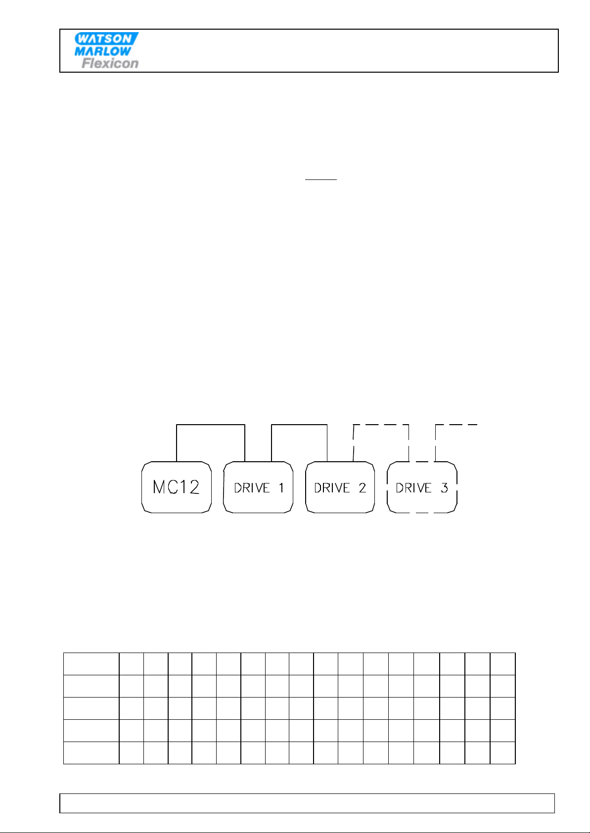
Up to 16 drives may be connected to the Flexicon network. The maximum length of the network
is 500 meters.
Figure 1 – Drive Connections
The network is physically connected through special Flexicon communication cables marked
"type 3". The MC12 is connected via a cable 3 to the first drive of the system, and subsequently
the individual drives are inter-connected with a cable 3. The last drive is provided with a
terminator which terminates the network.
It is important that each drive is allocated an individual address in order that the MC12 can
identify individual drives.
Address 1 2 3 4 5 6 7 8 9 10 11 12 13 14 15 16
SW1 1 0 1 0 1 0 1 0 1 0 0 1 0 1 1 0
SW2 1 1 0 0 1 1 0 0 1 1 0 1 1 0 0 0
SW3 1 1 1 1 0 0 0 0 1 1 1 0 0 0 0 0
SW4 1 1 1 1 1 1 1 1 0 0 0 0 0 0 0 0
Figure 2 – Switch address

Operators and Reference Manual
MC12
MC12 OM RM 1.03_EN Version: 1.03 Date: 2010-11-17 Page 7 of 46
The address is changed by setting a dip-switch positioned on the bottom of the drive. This
switch must only be activated when the drive is turned off at the main isolator. Addresses from 1
to 16 may be selected, and Fig. 2 shows the different combinations.
When the MC12 is started, the whole network is init ialised. The MC12 makes a global enquiry
on the network and receives feedback from the individual drives, allowing it to record how many
and which types of drives are available on the network.
When the drives have started their filling operations with their respective parameters, the MC12
will continuously scan the network to record when the drives have completed their tasks.
Finally all the counters are updated and the next job instruction (if any) is transmitted.
4. GENERAL INFORMATION
4.1 Unpacking and inspection
After checking that all ordered items have been received, please check that they were not
damaged during transport. In case of any defects or shortcomings, please contact Watson -
Marlow Flexicon A/S or your supplier immediately.
In case of future need of spare parts for this machine, please, when ordering, indicate the serial
number stamped on the label on the bottom of the machine.
ALWAYS REMEMBER that this machine must be earthed via its main cable.
4.2 Connections MC12P
When the MC12P is mounted at the top of the trolley, all connections are via the plugs and
sockets on the side of the trolley.
Using MC12P with stand-alone drive
See section : 10 MC12P INTERFACE
Using MC12P together with panel -mounted drive
See the pumps and MC12 electrical interface description in the Document Binder.
4.3 Connections MC12 table top model
See section: 11 MC12 (table top model) INTERFACE

Operators and Reference Manual
MC12
MC12 OM RM 1.03_EN Version: 1.03 Date: 2010-11-17 Page 8 of 46
5. CONTROL
5.1 Display
The display of MC12 consists of 4 lines each of 40 characters.
The display is lit from the back.
The blinking cursor of the display shows where a character will occur, if a key is activated.
ENTER FUNCTION No. :
F 1: 100.00 ml.
F 3: 200 rpm
F 5: 0 REV.
X1
F 2: 8.0 TUBE
F 4: 10 ACC
F 6: 1 fills
Figure 3 - Display
The top line is the typing line and also the line, where MC12 prompts the operator.
The second last character on the top line (X) indicates the operation principle of MC12:
Individual (I), Parallel (P) and Serial (S)
The ultimate character of the top line (1) indicates the pump connected.
The three lines below are status lines which always shows the current operating parameters.
These status lines can be scrolled by pressing the Up or Down Arrow of the keyboard.
When operating MC12, it is VERY important to wat ch the top line constantly, as any current
question or instruction will be written here.

Operators and Reference Manual
MC12
MC12 OM RM 1.03_EN Version: 1.03 Date: 2010-11-17 Page 9 of 46
5.2 Keypad
The MC12 comes with a membrane-type keypad.
The keypad is sealed and flat and can be cleaned with alcohol and other detergents.
7
4
1
8
5
2
9
6
3
C
.
0
calib.
Y
disp.
STOPGO
pump
N
ENT
7
4
1
8
5
2
9
6
3
C
.
0
Numerical keys 0 to 9
C
Y
N
“C” : Cancel
Delete Character
to the left of the
cursor
YES key for
YES/NO
questions on
display
NO key for
YES/NO
questions on
display
Scroll the
status line
one line up
calib.
disp.
pump
Decimal point
Activates
calibration
Activates filling
Activates
continuous
pumping
Scroll the
status line
one line down
ENT
GO
STOP
Enter / pressed after entering of values
typed on the keyboard.
Start Button Stop Button
Figure 4 - Keypad
Operators and Reference Manual
MC12
MC12 OM RM 1.03_EN Version: 1.03 Date: 2010-11-17 Page 10 of 46
6. PROGRAMMING
6.1 Starting the MC12
In the following, the sign <> will mean that the indicated key must be activated. For instance,
<ENT> means that ENTER must be pressed.
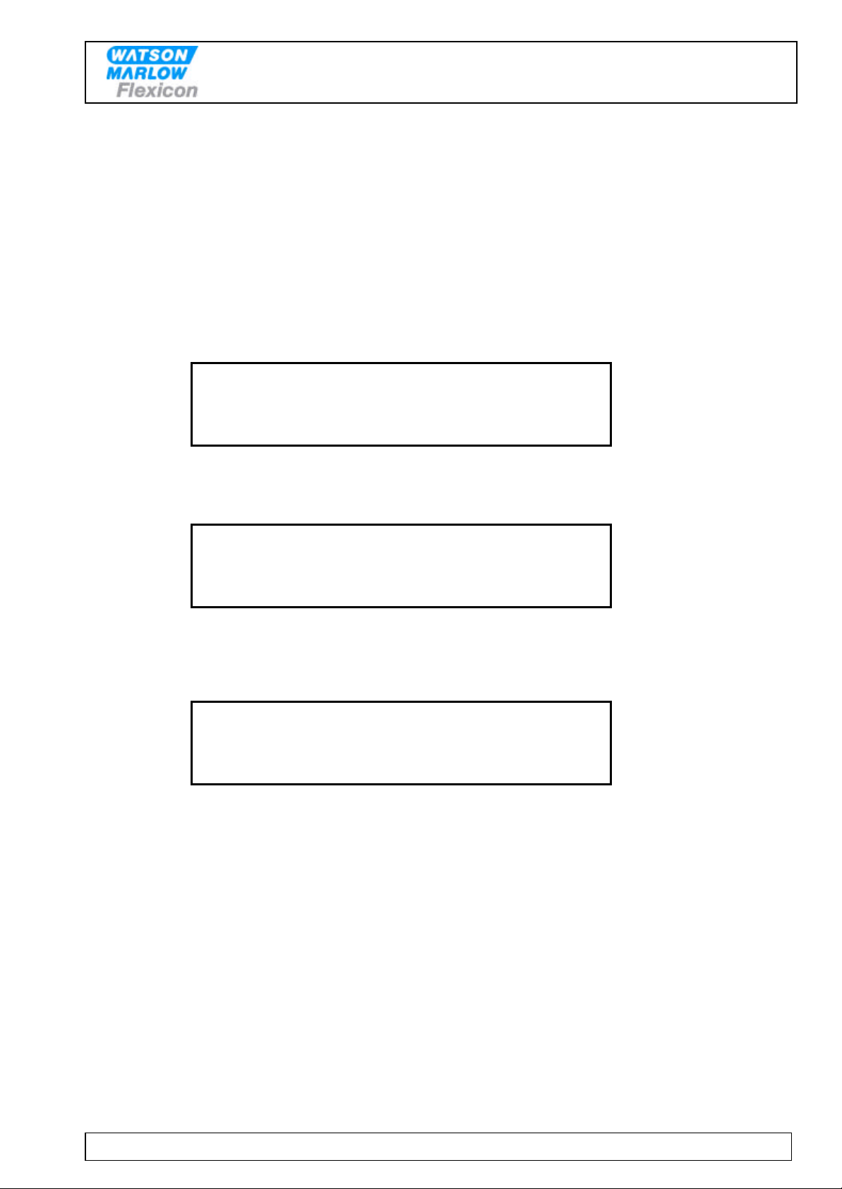
When the MC12 is connected, the main switch on the left side of the control box can be turned
on. The display will show the following:
STANDBY
Figure 5 – Starting MC12 -I
Press the <GO> key, and the display will show the following:
* MC12 V1. XX (C) Flexicon 90-XX *
PRESS GO TO CONTI NUE.
DRIVE No.: 1
Figure 6 – Starting MC12 -II
Verify that all connected drives are displayed with their respective numbers.
Then press <GO> once more, and the display will show the following:
ENTER FUNCTION NO. :
F 1: 100.00 ml.
F 3: 200 rpm
F 5: 0 REV.
I1
F 2: 8.0 TUBE
F 4: 10 ACC
F 6: 1 FILLS
Figure 7 – Starting MC12 -III
The values shown in the status lines will be the above or the latest values used.
Please note – that in MC12 special versions, pressing the GO key during start up is put out of
commission. Start-up runs without pressing GO.
6.2 Password Protection
MC12 is password protected. To be able to perform the following programming procedures it is
necessary to log on as a supervisor (see function 59).
Always remember to change the password level back to user level after programming.
Remember that merely switching MC12 off/on will NOT change any selected password level!

Operators and Reference Manual
MC12
MC12 OM RM 1.03_EN Version: 1.03 Date: 2010-11-17 Page 11 of 46
6.3 Parameters
In the following a parameter will be a single value like for example volume, velocity, number of
fillings etc.
6.4 Programs
In the following a program will be a complete set of parameters which together form a program
according to which MC12 and the connected pump will operate.
6.5 General information on the programming of MC12
MC12 is equipped with a battery in the memory and will therefore always remember the
programmed parameters, even if the main switch is turned off.
The programming is made via functions, i.e. every operating parameter has its own function
number.
The programming is made by entering the function number followed by "ENT".
This will make the required function appear in the prompt line of the display and show the current
value or information of the function.
This value will automatically be overwritten when entering the new value. After being entered, the
new value will be displayed in the prompt line. The new value is entered into the computer by
pressing "ENT".
The new value will be displayed in the status lines at once.
Example:
If a volume of 8.5 ml is required, the following should be entered:
<1>+<ENT>+<8>+<.>+<5>+<ENT>
MC12 knows automatically which filler is connected. Consequently, values which are not valid for
this pump will not be accepted.
If a faulty value is entered, it will not be entered, and a "beep" sound will be heard.

Operators and Reference Manual
MC12
MC12 OM RM 1.03_EN Version: 1.03 Date: 2010-11-17 Page 12 of 46
6.6 List of functions
1. Volume 32. Load program
2. Tube diameter 33. Delete program
3. Velocity 34. Print programs
4. Acceleration/deceleration 35. Free memory capacity
5. Reversing (back suction) 40. Mode
6. Batch size
(Disabled in FMB version)
41. Select filler
7. Delay
(Disabled in FMB version)
42. Set date
8. Completed fills 43. Set time
9. Specific gravity 44. View watch
10. Output rate 45. View version
11. Accumulated volume 46. Select language
12. Maximum flow rate 47. Printer set -up
16. Pumping direction (GD30I) 49. Balance set -up
17. Timer 1
(Disabled in FMB version)
52. Prime speed and acceleration
18. Timer 2 53. Drive deactivation !!
19. Timer 3 55. Number of pumps con nected
20. Operator number 58. Set passwords
21. Batch number 59. Change access level
22. Start Log
60. Ext. Input mode
(Disabled in FMB version)
23. Stop Log 70. Cap. format
24. Print Log 71. Flow format
25. Delete Log 72. Volume format
26. Log status 73. Display Mc12 version
29. Print parameters 80. Reset memory
31. Save program 86. Complete memory reset
Figure 8 – List of functions
Operators and Reference Manual
MC12
MC12 OM RM 1.03_EN Version: 1.03 Date: 2010-11-17 Page 13 of 46
6.7 Description of functions
The individual functions will be described in the following:
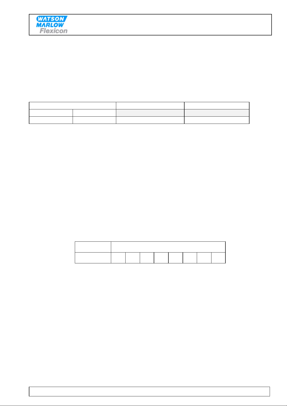
6.7.1. Function 1 -Volume
Value: Choice of ml and grams as unit.
Function 1 informs the system of the volume to be filled.
Value Option Related Function(s)
Min Max
0.01 9999.9 ml. or gram 72
The entered value must be between 0.01 and 9999.9. If a value ou tside these limits is entered,
the MC12 will correct the value to the nearest value within the limits and ask for acceptance via
<ENT>.
When a volume is entered, the system will calculate the new parameter value which will then be
used from the start of the next fill. At the same time, the status line will be updated.
For an individual fill only the parameter value for the drive in question will be changed.
For parallel or serial filling, the volume should be entered in drive 0 and the parameter value will
be calculated for all connected drives.
6.7.2. Function 2 - Tube diameter
Value: Inside diameter of the tube in mm.
Drive type Tube inside diameter in mm
PD12P 0.5 0.8 1.2 1.6 3.2 4.8 6.0 8.0
Enter the tube diameter used. The MC12 will only accept original Flexicon tube diameters.
The diameters are specified in the manual for the drive and can be read on the tube gauge
supplied with the drive.
As most of Flexicons drives are of the peristaltic type and work with tubes, the system must know
the current tube diameter.
When programming a drive that does not use tubes as pumping element, this function will not be
activated.
The tubes should be indicated by their inside diameter and from these data the MC12 will
calculate how many revolutions the selected pump head should make in order to dispense the
required volume.
If an unrecognised tube diameter is entered for the selected drive, the MC12 will not accept this
diameter but will instead ask for a tube diameter from the original Flexicon range.
Operators and Reference Manual
MC12
MC12 OM RM 1.03_EN Version: 1.03 Date: 2010-11-17 Page 14 of 46
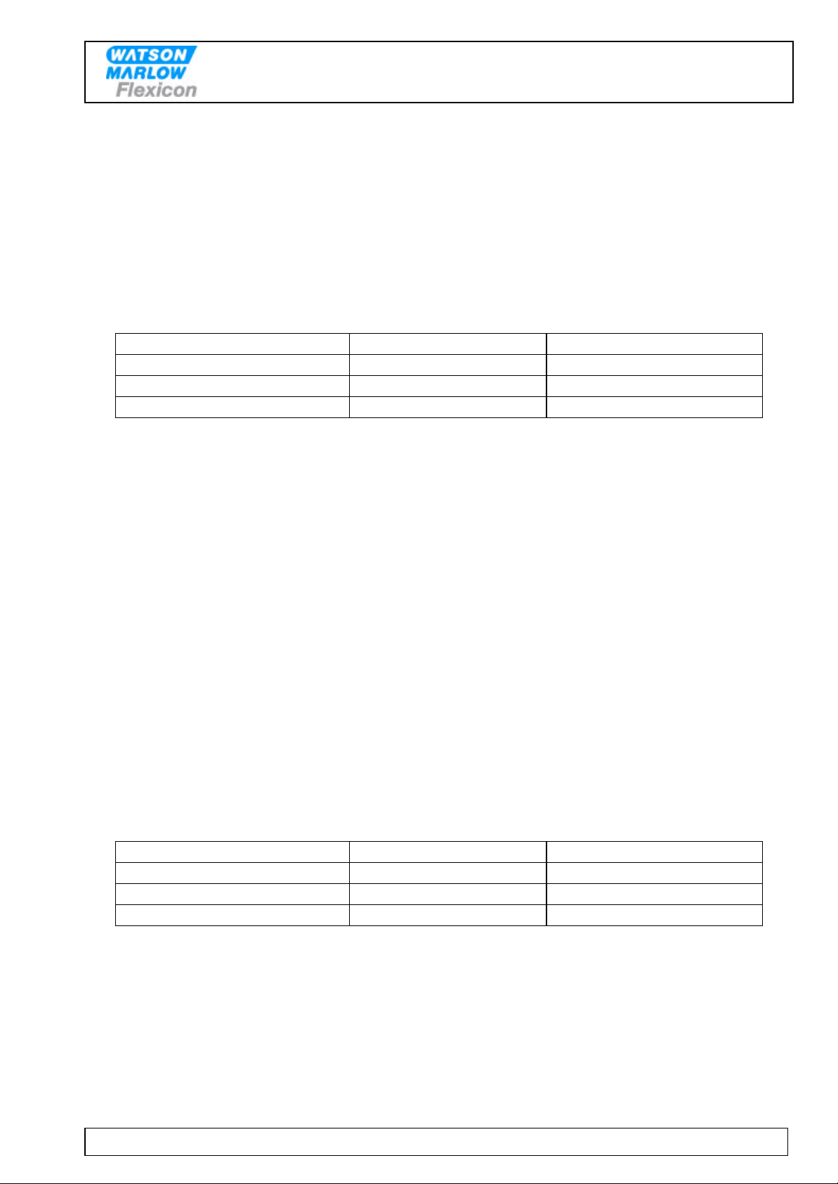
6.7.3. Function 3 - Velocity
Value: Revolutions per minute (rpm).
Enter the required velocity.
Velocity range depends on tube size applied.
Range:
Tube Sizes Max. Velocity Max. acceleration
0.5 - 0.8 – 1.2 – 1.6 600 200
3.2 500 150
4.8 - 6.0 – 8.0 400 100
If a value outside the range is entered, the MC12 will automatically correct the value to the
closest value allowed and the operator has to accept it by pressing the <ENT> key.
The fastest filling will be carried out at the highest velocity setting but the velocity should always
be adjusted to suit the characteristics of the product and to reduce splashing or foaming.
If the velocity is changed during a fill, the fill will be completed using the original parameters and
the new value will not be applied until the start of the next fill.
If the velocity is changed while using the unit as a pump, the drive will apply the new parameters
immediately. The change will be carried out at the acceleration or deceleration entered in
Function 4.
6.7.4. Function 4 - Acceleration/deceleration
Value: An integral number.
The filling can start and stop more or less abruptly.
This function offers a choice of values between 1 and 200 dependent on the tube size and drive;
1 = slowest, 200 = fastest.
Tube Sizes Max. Velocity Max. acceleration
0.5 - 0.8 – 1.2 – 1.6 600 200
3.2 500 150
4.8 - 6.0 – 8.0 400 100
If a value outside the range is entered, the MC12 will automatically correct the value to the
closest value allowed and the operator has to accept it by pressing the <ENT> key.
The function is used for optimizing the filling according to the product and the shape of the bottle.
Function 4 affects pumping as well as filling and calibration.
If the value of the parameter is changed during a fill or calibration, the new value will not be
applied until the start of the next fill or calibration.
 Loading...