


505Di
505di-gb-03.pdf

Declarations
Declaration of |
When this pump unit is used as a stand alone pump it complies with: Machinery Directive |
|||
conformity |
98/37/EC EN60204-1, Low Voltage Directive 73/23/EEC EN61010-1, EMC Directive |
|||
|
|
|
89/336/EEC |
EN50081-1/EN50082-1. |
|
|
|
|
|
|
|
|||
|
|
|||
Declaration of |
When this pump unit is to be installed into a machine or is to be assembled with other |
|||
Incorporation |
machines for installations, it must not be put into service until the relevant machinery has |
|||
|
|
|
been declared in conformity with the Machinery Directive 98/37/EC EN60204-1. |
|
|
|
|
|
|
Responsible person: Christopher Gadsden, Managing Director, Watson-Marlow Limited, Falmouth, Cornwall TR11 4RU, England. Telephone 01326 370370 Fax 01326 376009.
Three year warranty
Watson-Marlow Limited warrants, subject to the conditions below, through either Watson-Marlow Limited, its subsidiaries, or its authorised distributors, to repair or replace free of charge, including labour, any part of this product which fails within three years of delivery of the product to the end user. Such failure must have occurred because of defect in material or workmanship and not as a result of operation of the product other than in accordance with the instructions given in this manual.
Conditions of and specific exceptions to the above warranty are:
∙Consumable items such as tubing and rollers are excluded.
∙Products must be returned by pre-arrangement carriage paid to Watson-Marlow Limited, its subsidiaries, or its authorised distributor.
∙All repairs or modifications must have been made by Watson-Marlow Limited, its subsidiaries, or its authorised distributors or with the express permission of Watson-Marlow Limited, its subsidiaries, or its authorised distributors.
∙Products which have been abused, misused, or subjected to malicious or accidental damage or electrical surge are excluded.
Warranties purporting to be on behalf of Watson-Marlow Limited made by any person, including representatives of Watson-Marlow Limited, its subsidiaries, or its distributors, which do not accord with the terms of this warranty shall not be binding upon Watson-Marlow Limited unless expressly approved in writing by a Director or Manager of Watson-Marlow Limited.
Information for returning pumps
Equipment which has been contaminated with, or exposed to, body fluids, toxic chemicals or any other substance hazardous to health must be decontaminated before it is returned to Watson-Marlow or its distributor.
A certificate included at the rear of these operating instructions, or signed statement, must be attached to the outside of the shipping carton.
This certificate is required even if the pump is unused. If the pump has been used, the fluids that have been in contact with the pump and the cleaning procedure must be specified along with a statement that the equipment has been decontaminated.
Safety
In the interests of safety, this pump and the tubing selected should only be used by competent, suitably trained personnel after they have read and understood this manual, and considered any hazard involved.
Any person who is involved in the installation or maintenance of this equipment should be fully competent to carry out the work. In the UK this person should also be familiar with the Health and Safety at Work Act 1974.
There are dangerous voltages (at mains potential) inside the pump. If access is required, isolate the pump from the mains before removing the cover.
Recommended operating procedures
DO keep delivery and suction lines as short as possible using a minimum number of swept bends.
DO use suction and delivery pipelines with a bore equal to or larger than the bore of the tube fitted in the pumphead. When pumping viscous fluids, the losses caused by increased friction can be overcome by using pipe runs with a cross sectional area several times greater than the pumping element.
2
DO run at a slow speed when pumping viscous fluids. When using the 501RL pumphead, a 4.8 or 6.4mm bore tube with a 1.6mm wall will give best results. Tube diameter smaller than this will generate a high -friction pressure loss, so reducing the flow. Tube with a larger bore will not have sufficient strength to restitute. Flooded suction will enhance pumping performance in all cases, particularly for materials of a viscous nature. Silicone, Marprene and Neoprene tubing is available with a 2.4mm wall thickness for speeds up to 200rpm. (The rotor will require re-setting to a roller/track gap of 3.8mm.)
DO fit an extra length of pump tube in the system to enable tube transfer. This will extend tube life and minimise the downtime of the pumping circuit.
DO keep the track and rollers clean.
The self-priming nature of peristaltic pumps means valves are not required. Any valves fitted must cause no restriction to flow in the pumping circuit.
When using Marprene tubing, after the first 30 minutes of running, re-tension the tube in the pumphead by releasing the tube clamp on the delivery side a little and pulling the tube tight. This is to counteract the normal stretching that occurs with Marprene which can go unnoticed and result in poor tube life.
Tube selection The chemical compatibility list published in the WatsonMarlow catalogue is only a guide. If in doubt about the compatibility of a tube material and the duty fluid, request a tube sample card for immersion trials.
Installation
The 505Di is suitable for single phase mains electricity supplies only.
To ensure correct lubrication of the gearbox the pump should be run only while its feet are standing on a horizontal surface. The pump should be positioned to allow a free flow of air around it.
∙ Set the voltage selector to either 120V for 100-120V 50/60Hz supplies or 240V for 220-240V 50/60Hz supplies.
A mains cable fitted with a moulded plug is supplied with the pump. The wires are colour coded in accordance with the following code:
∙220-240V: LiveBrown; Neutral - Blue; Earth - Green/Yellow.
∙100-120V: Live - Black; Neutral - White; Earth - Green.
Reduced voltage operation
In areas where voltage is below that specified above, modifications can be made to the pump unit to allow operation under the following minimum voltage levels:
∙180V when using the 220-240V setting.
∙90V when using the 100-120V setting.
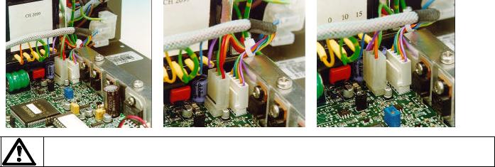
The modification requires the connector J8 on the Control PCB to be reversed. To locate the terminal, isolate the mains supply then remove the pump cover. State A shows the standard voltage setting, whilst State B shows the reduced voltage setting. Any damage caused to the pump in the process of carrying out this modification will not be covered by warranty.
Control PCB |
State A |
State B |
Refer servicing to qualified personnel only.
Troubleshooting
Should the pump fail to operate, make the following checks to determine whether or not servicing is required.
∙Check that the power switch is on.
∙Check the mains supply is available at the pump.
3
∙Check the voltage selector switch is in the correct position.
∙Check the fuse in the mains socket.
∙Check that the pump is not stalled by incorrect fitting of tubing.
∙Check that the keypad lock is not switched on.
User interfacing
When powering up the pump the user will be taken into the main menu.
Use the Step key to move between menu options. Use the Enter key to confirm settings. Use the number keys to enter in settings. Use the Ù or Ú key to increase or decrease set values in the pump software i.e. ramp settings, date, rpm etc.
Dose permits the set-up of doses for dispensing. A dose can be initiated by using the Start button or external switching. The pump will allow up to 26 dosing programs to be stored and recalled at any time. A printer can be connected to the pump for recording of dispense runs. Batch and operator codes must be entered when using a printer.
Cal allows the pump to be calibrated for accurate dosing.
Manual allows continuous transfer/fluid metering via keypad control.
Network enables RS232 control
Set-up displays and controls the user and factory settings for the correct operation of the pump.
The speed/volume flow rate of the drive is governed by the pumphead and tubing selected. Factory default is for a 501RL using 8.0mm bore tubing which means the max rpm/volume flow rate of the pump is 300 rpm/3000ml/min.
Dosing procedure
The Dosing program is outlined in the technical data section of the operating instruction in a flow chart format. Each step in the procedure is described to provide full understanding of the procedure.
Print audit routines
If a printer is connected, the completion of a dose run will automatically call the print routine. The first request will be to enter the operator ID.
Up to 16 characters can be entered. Digits and the decimal point are entered directly from the keypad. Alpha characters are entered by pressing Ù or Ú which call A to Z and Z to A respectively in circular rotation.
An alpha character is embedded by pressing Step. A numeric character is entered by pressing Step , any other numeric character, the decimal point or Ù or Ú.
On pressing Enter, the pump will request the input of a batch number.
Again, up to 16 characters can be entered as for the operator identity. When Enter is again pressed, the following information is printed out: date, time, dose size, specific gravity, dose interval, number of doses, initial ml/rev, recalibration data, operator identity, batch number and number of doses delivered.
Following the print out a repeat dose option will be given.
Single dose command
Single doses can be dispensed on demand, with a count of the number of doses being kept.
Set the interval time to 0 SECONDS and the number of doses to 1.
To start single dosing, press Start or use an external start dose switch. The display will indicate the total number of completed doses up to a maximum of 99,999 after which the counter will restart at 0, so that dose 100,001 would be shown as 1.
Calibration procedure
Calibration of the 505Di is based on informing the pump under Cal of the pumphead and tubing which are to be used. Alternatively a calibration dose can be used. The calibration dose will run for a maximum of 4 minutes, but can be stopped at any time up to 4 minutes. The longer the calibration dose the more accurate the calibration. Entering into the pump the physical volume (ml) or mass (sg) to complete the procedure and will allow the pump to take into account ambient conditions and also the viscosity of the fluid.
Manual operation
∙Switch power on (drive rear panel).
∙Change the set speed by pressing the Ù or Ú key. The minimum speeds of the 220rpm and 350rpm drives are 1rpm and 2 rpm respectively.
4
∙Change direction by pressing the CW/CCW key. Indication of direction of rotation is provided via the LCD display.
∙Select the maximum speed : press the Ù key and the Max key together. Select the minimum speed: press the Ú key and the Max key together.
∙Press Start to start the pump. Press Stop to stop the pump.
Network
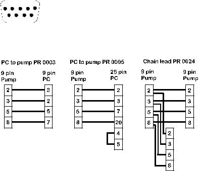
This facility gives full pump functionality under RS232 closed loop control via the 9 pin D connector. Up to 16 pumps can be linked whilst still retaining individual pump control by using lead PR 0024. A network kit is available from WatsonMarlow which includes Pumpnet 2, a DOS compatible control program and leads.
Step to Network in the Main menu and press Enter. The pump will now be under RS232 control. The keypad Stop key will act as an emergency stop and disable RS232 settings if pressed.
5 |
1 |
9 6
Connections for RS232 signals (viewed from inside the plug)
RS232 cabling shown for CTR handshake
Use only twin shielded RS232 cables. |
|
|
||
RS232 settings |
|
|
||
Baud = 9600 ; |
Stop bits = 2 ; Data bits = 8 ; Parity = None ; Handshake = CTR or None; Auto echo = On |
|||
|
|
|
|
|
Pin |
|
Function |
Pin |
Function |
1 |
|
- |
6 |
- |
2 |
|
RX (Receive data) |
7 |
RTS (Request to send) |
3 |
|
TX (Transmit data) |
8 |
CTS (Clear to send) |
4 |
|
- |
9 |
- |
5 |
|
GND (Ground) |
|
|
The following codes will operate the 505Di under RS232 control. They must be directed to the pump from a computer serial port (or equivalent). Always terminate each command with a RETURN (ASCII CHR13).
nSPxxx |
Load speed setting xxx to pump number n |
nSI |
Increment speed by 1rpm for pump n |
nSD |
Decrement speed by 1rpm for pump n |
nGO |
Start pump number n |
nST |
Stop pump number n |
nRC |
Change rotation direction for pump n |
nRR |
Set clockwise direction for pump n |
nRL |
Set anti-clockwise direction for pump n |
nDOxxxxx,yyy |
Set dose for pump number n in tachometer pulses (note 3) |
nRS |
Show status for pump number n (note 4) |
5
nZY |
Show status if pump n STARTed 1 or STOPped 0 |
nTC |
Clear tachometer counter |
nRT |
Read tachometer counter |
For writing to pump number n display |
|
nCA |
Clear existing display; followed by: |
nCH |
"Home" cursor; followed by; |
nW{text line 1}~{text line 2}@ ( @ = terminator )
Notes on control codes
1n = pump number set in Set-up. For the command to operate on all networked pumps simultaneously, use # before the command.
2There are 800 tacho pulses per pumphead revolution on the 350rpm version, 1280 tacho pulse per revolution on the 220rpm version.
3nDOxxxxxxxx where xxxxxxxx is any integer and is the target dose in tacho pulses. This can be extended to nDOxxxxxxxx,yyy where yyy is a "kick back" in tacho pulses with a limit of 255 (about 1/5 of a revolution on a 220rpm drive or a 1/3 of a revolution on the 350rpm drive).
4A show status command will prompt the 505Di to return a text string of the following layout:
[pump type] [ml/rev] [pumphead] [tube size] [speed] [cw/ccw] [P/N] [pump number] [tacho count as a single integer] [stopped/running, 0 /1] [! = delimiter]
e.g. 505Di 0.7 505l 1.6mm 53.5 CW P/N 1 157810 1 !
5All networked pumps with the same n will respond to the same command.
6There should be at least 10mS between consecutive commands.
7When using the # to address all pumps, ensure that it will not generate a reply, e.g. nSS, the result will be unpredictable.
This is a typical short program for pump number 2:
OPEN "COM1:9600,N,8,2,CDO,CSO,DSO,OP10000" FOR RANDOM AS #1
PRINT #1, "2SP220" + CHR$(13)
DELAY
PRINT #1, "2GO" + CHR$(13)
DELAY 5000
PRINT #1, "2ST" + CHR$(13)
CLOSE #1.
RS232 Remote dosing
The following commands enable a remote dose to be requested and repeated.
Note that in accordance with the existing command set, the ‘nn’ field can be either one or two decimal numeric characters in the range 01 to 16. Or the single character ‘#’ for a broadcast command.
All commands are terminated with Carriage Return (0x0D). All characters are ASCII.
Program Dose
The syntax of the command to program a dose into the pump is given below. No response is given. The programmer is advised to check that the command has been correctly received by issuing the ‘nnPD?’ command.
nnPDdddddKRssssSED
where
PD Program Dose Command Characters
ddddd Five character dose size in the range .0001 to 99999 with leading and trailing zeros to form a fixed size field. E.g. 10 is programmed 10.00
KDose size modifier. This determines the scale of the dose size ddddd'. The modifier may only consist of three characters these are:
lDose size is in litres
mDose size in millilitres
uDose size in microlitres
R Direction of rotation. This is a single character:
6
A Anticlockwise
CClockwise
ssss Four character speed field in tenths of an rpm in the range of 0001 to 2200 with leading and trailing zeros to form a fixed size field. The maximum speed is dependant upon the type of pumphead used or tubing which is fitted in the pumphead. e.g. 195 rpm is programmed as 1950
S Start ramp value.. Characters '0' to '5' ( '0' = none '5' = maximum)
E End ramp value.. Characters '0' to '5' ('0' = none '5' = maximum)
D Drip value.. Characters '0' to '5' ('0' = none '5' = maximum)
Characters outside the range specified in the fields, or omission of any fields or parts thereof cause the whole document to be discarded. An error message is issued on the screen of the pump.
The dose size, ramps and drip values issued by this command overwrite the internal values, normally accessed by the SETUP screen.
The issuing of this command, resets the internal motor overrun value to its nominal setting if the speed changes. Thus typically four doses are required to enable the pump to converge onto the average overrun value, thus increasing the accuracy of the dose.
This command always resets the batch count. See the Report Batch Count command 'nnSC'.
Query dose
The syntax of the command to verify the loading of a dose is:
nnPD?
This elicits the response:
dddddKRssssSED !
where field definitions are given in Program Dose Command.
Note that the dose size after scaling is held internal in millimetres. Thus if a dose size of 0.895m is programmed, the response will be 895.0µ (i.e. 895 microlitres). Dose sizes in excess of 999ml will be reported in litres.
Clear batch count
The syntax of the command to clear the batch count is:
nnCC?
This command does not elicit a response. It clears the batch count without affecting any other pump parameters. See the Report Batch Count command 'nnSC'.
Show batch count
This syntax of the command to view the batch count is:
nnSC
This elicits the response:
ccccc !
where ccccc is a five digit decimal field in the range 00000 to 99999.
This consists of the number of complete doses delivered since the last program dose command. The dose may be initiated with either a Run program 'nnRP' or a footswitch press.
Run program
The syntax of the command to repeat a dose, either in tacho pulses or dose size is:
nnRP
This command does not elicit a response. When the dose has been delivered the batch count is incremented. This is primarily designed for use with the Program Dose command, 'nnPDxxx…xx'.
It will cause a dose specified in tacho pulses ('nnDIxxx' or 'nnDOxxx' commands) to be repeated.
Please note
The default program dose is 5.0ml, Clockwise, 220.0rpm, Start ramp = 2. No End ramp or Drip value.
Doses specified by the 'nnDI' or 'nnDO' can be repeated using the footswitch or the 'nnRP' command.
Changing, incrementing or decrementing the motor speed using the nnSPxxx', nnSI' or nnSD' commands reset the motor overrun value to its nominal value.
7
If the motor is dosing, it has no effect until the next dose. Typically four further doses are required to achieve maximum dose accuracy. Then the pump will have converged on the average motor overrun value.
Set-up
ROM - provides user with software identification
Date/Time - Set during manufacture but can be reset to user requirements.
Beep - Audible signal on/off.
Ramp - Rate of acceleration/deceleration of the pump to/from maximum set speed at the beginning/end of a dose. 0 setting signifies no acceleration delay to maximum speed, 5 signifies the longest acceleration delay to maximum speed. The pump default setting is 2.
Drip - Brief reversal of the motor on dose completion ensures no extra drips of fluid are dispensed. 0 means no reverse and 5 means maximum reverse.
Baud - Speed of signal transmission. Default setting 9600, range of setting include 1200, 2400, 4800, 9600.
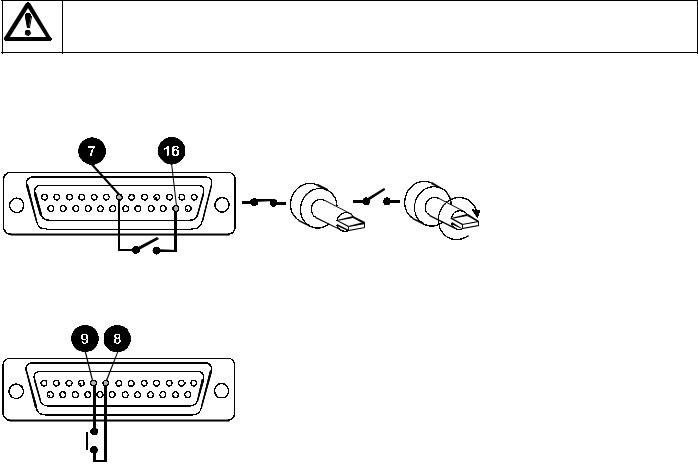
Auxiliary - Monitor the pump dosing or motor state/direction of rotation using 2 high/low auxiliary signals outputted via the pumps 25D connector. Auxiliary signals can be used, for example, to command a turntable or conveyor to move when a dose has been completed.
Line 1 can be set to change state every time the motor runs, or only when the motor runs to dispense a dose. The signal can be set high or low when the motor runs. Line 2 changes state when the pump direction is changed. The screens allow the signal to be set high or low when the output shaft rotates clockwise.
Pump - When under RS232 control each individual pump must be identified. Select a number from 1-16.
Default - Press Enter at Yes to restore factory defaults.
Autostart - If set to On, when operating in Manual mode only, Autostart will allow the pump to restart pumping automatically after power-up following a mains supply interruption. If set to off the pump will restart and return to the Main Menu.
Remote control
Never apply mains voltage across pins on the 25D socket. Up to 5V TTL may be applied to pins 7 and 5, but do not apply voltage across any other pins. Permanent damage not covered by warranty may result.
Pause dose/ Remote stop start
This function will pause a dose on for as long as a remote switch remains closed then allows the dose to continue when the switch is opened. Under Manual mode it will also act as a remote stop/start. Connect remote switch as in diagram. Open to run pump, close to pause or stop pump.
Start Dose
A Watson-Marlow footswitch or handswitch can be used to start the dose. If not supplied by Watson-Marlow then select "Other" in the pumps software. Use instantaneous contacts only.
8
Care and maintenance
The only scheduled maintenance required on the 505Di is to inspect the motor brushes and to replace them before their length is less than 6mm 1/4". The life of the brushes will depend on the duty of the pump, which is expected to be at least 10,000 hours at maximum speed. When the pump needs cleaning, remove the pumphead and use a mild solution of detergent in water. Do not use strong solvents.
If the gearbox is rebuilt you should use 15 ml of the recommended lubricant, which is RD105, this is a SAE 30 mineral oil loaded with molybdenum disulphide to form a soft fluid grease.
Specification
Maximum rotor speeds |
220rpm, 350rpm |
Voltage/frequency |
100-120/220-240V 50/60Hz |
Control range |
220rpm; 220:1, 350rpm 175:1 |
Power consumption |
100VA |
Shaft Torque |
2.2Nm |
Operating temperature range |
5 to 40C |
Storage temperature range |
-40C to 70C |
Weight 505Di/RL |
7.5kg |
Weight 505Di/L |
8.9kg |
Noise |
<70dBA at 1m |
Standards |
IEC 335-1, EN60529 (IP31) |
|
Machinery Directive 98/37/EC EN60204- 1 |
|
Low Voltage Directive 73/23/EEC EN61010- 1 |
|
EMC Directive:89/336/EEC EN50081-1 / EN50082-1 |
Specific drive performance details such as loaded drive speed variation against mains supply voltage fluctuation and drive stability from a cold start to normal operating temperature are available on request. For further information please contact Watson-Marlow Technical Support Department.
501RL Pumphead
The 501RL pumphead has two spring-loaded working rollers, which automatically compensate for minor variations in tubing wall thickness, giving extended tube life. The 501RL is set during manufacture to accept tubing with wall thicknesses of between 1.6mm and 2.0mm, and internal diameters of up to 8.0mm. It is equipped with a "tool lockable" guard for increased safety. This should be locked shut whilst the pump is in use.
The pumphead can be run clockwise for extended tube life, or anti-clockwise to operate against higher pressures.
Flow rates
Flow rates for the 505Di were obtained using silicone tubing with the pumphead rotating clockwise, pumping water at 20C with zero suction and delivery pressures. For critical applications determine flow rates under operating conditions.
501RL Installation
Fit the track in any one of three orientations, over the drive shaft and locating boss. Secure the track with the locating screw. Ensure the drive shaft is degreased before locating the rotor onto the shaft via the split collet. Rotate the rotor until its guide rollers are alligned flush to the front edge of the track. Tighten the rotor screw to a torque of 3Nm to prevent the collet slipping during operation.
To reposition the track, swing out the crank handle to expose the rotor retaining screw. Turn the screw anticlockwise one turn to release the collet, and withdraw the rotor from the shaft. Loosen the track locating screw, and pull the track clear. Rotate the track to its new position and tighten the track locating screw. Use this method of removal and fitting in case cleaning is required.
Tube loading
Isolate pump from mains supply. Unlock and open the hinged guard and swing out the rotor crank handle until it locks into position. Select the length of tubing required, noting that approximately 240mm is required for the pumphead.
Fit one end of the tubing into one of the spring loaded clamps, and then, whilst rotating the rotor with the crank handle, feed the tubing between the rollers and the track, aligning it within the rotor tube guides. The tubing must lie naturally against the track and must not be twisted or stretched.
9
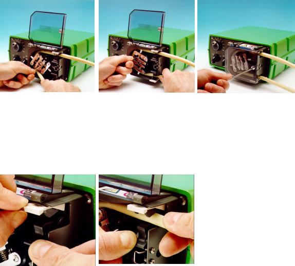
Fit the other end of the tubing into the second spring loaded clamp, ensuring that the tubing is not slack in the pumphead, since this can reduce tube life.
Close the crank handle and shut and lock the guard.
After the pump has been started, open the downstream clamp for a short time, so that the tube can find its natural length.
The 501RL pumphead is fitted with four-position tube clamps, to accommodate various tube diameters, which can be adjusted by pushing in or pulling out the bars at the top of the upper clamp and the bottom of the lower clamp. Set the clamps so that the minimum necessary pressure is applied to the tubing.
Roller adjustment
The 501RL has a factory set gap of 2.6mm between the rollers and the track and is suitable for tubing having wall thicknesses of between 1.6 and 2.0mm. Adjustment of the gap will be required if tubing having a wall thickness of less than 1.6mm is required. There is an adjusting screw on each of the two roller arms, and each of these screws will require adjustment. The correct gap is twice the wall thickness less twenty percent. Correct adjustment is important: over occlusion will reduce tube life; under occlusion will reduce pumping efficiency.
To change the gap setting, turn each adjusting screw clockwise to increase the gap, or anticlockwise to decrease the gap. A full turn changes the gap by 0.8mm.
To restore the original settings of 2.6mm, turn the adjusting screws until both rollers are just touching the track, then tighten each screw by three and a quarter turns. The 501RL2 has a factory set gap of 3.8mm between the wall and the track and is suitable for tubing having wall thickness of between 2.1 and 2.5mm.
Check moving parts of the rotor from time to time for freedom of movement. Lubricate pivot points and rollers occasionally with Teflon lubricating oil.
10
Pumphead spares
Number |
Spare |
Description |
1 |
MN 1200M |
Lockable guard |
2 |
FN 4502 |
Lock |
3 |
FN 2341 |
Hinge screw |
4 |
MN 0266M |
Hinge grey |
5 |
MNA0623A |
Tube clamp assembly |
6 |
FN 2332 |
Screw |
7 |
MN 0011T |
Main roller |
8 |
MNA0143A |
501RL Rotor Assembly |
9 |
SG0001/SG0002 |
Springs standard/hard |
10 |
MN 0012T |
Follower roller |
|
XX 0095 |
Teflon lubricant |
11

505L pumphead
The twin offset track design of the 505L utilises 2.4mm wall double-y tube elements to overcome pulsation for accurate dosing and dispensing. The 505L accepts Silicone and Marprene tubing up to 9.6mm bore giving a potential flow rate of 2400 ml/min per pumphead. (Fit the 505LX for flow rates up to 4800ml/min). Use 2.4mm wall tube for transfer for the highest performance and improved viscous fluid handling.
Alternatively the 505L will run with two separate tubes although some channel to channel variance and minimal pulsation may be experienced. For separate tube fitting or twin tube inlet to single tube outlet fitting tube clamping blocks must be used.
505L Installation
Remove the mounting plate cover from the 505L. Align the drive shaft dog and 505L centre shaft slot and push the pumphead on to drive. Tighten top and bottom mounting plate screws.
505LX Installation
Remove the 505L bowed front plate by undoing the two retaining screws (inside front face of 505L). Grease drive dog of 505LX. Align 505LX drive dog and 505L slot in centre shaft. Locate 505LX to 505L. Tighten the fixing screws at the mating faces of the 505L and 505LX. Locate the bow front onto the 505LX and fit using the two retaining screws (inside front face of 505LX).
12
 Loading...