


Watson-Marlow Bredel E-Manuals |
Page 1 of 46 |
|
|
Search manual for ... |
Go |
|
|
WATSON-MARLOW BREDEL E-MANUALS
m-621cc-gb-04
Watson-Marlow 621 close-coupled pumps
Clickable index
1. |
Declaration of conformity |
|
|
|
2. |
Declaration of incorporation |
14. |
Air motors |
|
3. |
Warranty |
15. |
Pump specification |
|
4. |
Information for returning pumps |
16. |
620RE, 620RE4 and 620R Key safety |
|
5. |
Safety |
|
|
information |
6. |
Do's and do not's |
17. |
620RE, 620RE4 and 620R Safe-guarding |
|
7. |
Installation |
18. |
620RE, 620RE4 and 620R Pumping |
|
8. |
Start-up |
|
conditions |
|
9. |
Troubleshooting |
19. |
620RE, 620RE4 and 620R Pump |
|
10. |
AC motor maintenance |
|
installation |
|
11. |
Gearbox maintenance - Simplex |
20. |
620RE, 620RE4 and 620R General |
|
|
(single pumphead) units |
|
operation |
|
12. |
Gearbox maintenance - Duplex (twin |
21. |
620RE and 620RE4 tube element loading |
|
|
pumphead) units |
22. |
620RE, 620RE4 and 620R Continuous tube |
|
13. |
Varmeca drives |
|
loading |
|
|
13.1 |
Varmeca drives: installation |
23. |
620RE, 620RE4 and 620R Tube element or |
|
13.2 |
Varmeca drives: connections |
|
continuous tube removal |
|
13.3 |
Varmeca drives: cables and |
24. |
620RE, 620RE4 and 620R Maintenance |
|
protection devices |
25. |
620RE, 620RE4 and 620R CIP and SIP |
|
|
13.4 |
Varmeca drives: |
26. |
Pumphead spares |
|
commissioning / start-up |
27. |
Technical data |
|
|
13.5 |
Varmeca drives: single phase |
28. |
Motor wiring for three-phase motors |
|
connection diagram |
29. |
Dimensions in mm |
|
|
13.6 |
Varmeca drives: keypad |
30. |
620R product codes |
|
indicator light display |
31. |
620RE and 620RE4 LoadSure product |
|
|
13.7 |
Varmeca drives: Varmeca-30 |
|
codes |
|
specifications |
32. |
Trademarks and disclaimer |
|
|
13.8 |
Varmeca inverter factory |
33. |
Patient-connected use: warning |
|
settings |
34. |
Publication history |
|
|
13.9 |
Varmeca care and |
35. |
Decontamination certificate |
maintenance
Double clicking anywhere in the manual will take you back to this index.
file://R:\staging\pdfs-global\m-621cc-gb-04.html |
21/12/2011 |
Watson-Marlow Bredel E-Manuals |
Page 2 of 46 |
file://R:\staging\pdfs-global\m-621cc-gb-04.html |
21/12/2011 |
Watson-Marlow Bredel E-Manuals |
Page 3 of 46 |
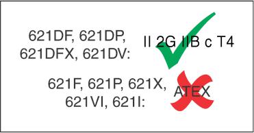
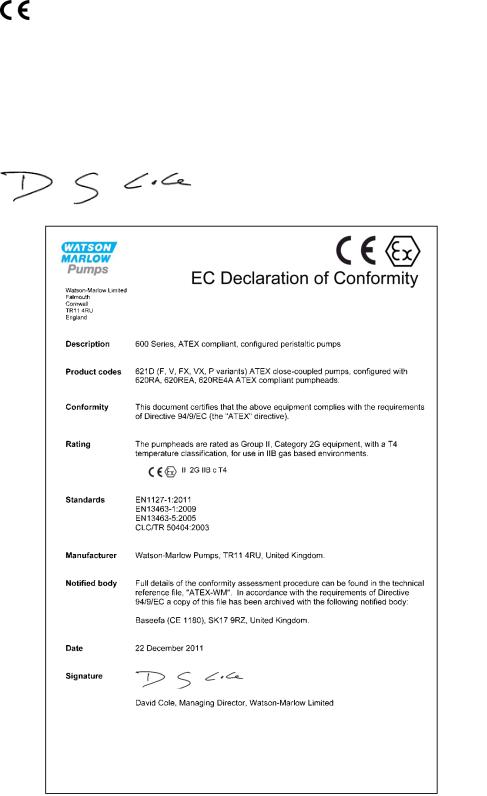
1 Declarations of conformity
When this pump unit is used as a stand-alone pump it complies with: Machinery Directive 2006/42/EC, EMC Directive 2004/108/EC.
2 Declaration of incorporation
When this pump unit is to be installed into a machine or is to be assembled with other machines for installations, it must not be put into service until the relevant machinery has been declared in conformity with the Machinery Directive 2006/42/EC.
Responsible person: David Cole, Managing Director, Watson-Marlow Limited, Falmouth, Cornwall TR11 4RU, England. Telephone +44 (0) 1326 370370 Fax +44 (0) 1326 376009.
file://R:\staging\pdfs-global\m-621cc-gb-04.html |
21/12/2011 |
Watson-Marlow Bredel E-Manuals |
Page 4 of 46 |
3 Two year warranty
Watson-Marlow Limited warrants, subject to the conditions below, through either WatsonMarlow Limited, its subsidiaries, or its authorised distributors, to repair or replace free of charge, including labour, any part of this product which fails within two years of delivery of the product to the end user. Such failure must have occurred because of defect in material or workmanship and not as a result of operation of the product other than in accordance with the instructions given in this manual.
Conditions of and specific exceptions to the above warranty are
Consumable items such as tubing and rollers are excluded.
Products must be returned by pre-arrangement carriage paid to Watson-Marlow Limited, its subsidiaries, or its authorised distributor.
All repairs or modifications must have been made by Watson-Marlow Limited, its subsidiaries, or its authorised distributors or with the express permission of WatsonMarlow Limited, its subsidiaries, or its authorised distributors.
Products which have been abused, misused, or subjected to malicious or accidental damage or electrical surge are excluded.
Warranties purporting to be on behalf of Watson-Marlow Limited made by any person, including representatives of Watson-Marlow Limited, its subsidiaries, or its distributors, which do not accord with the terms of this warranty shall not be binding upon WatsonMarlow Limited unless expressly approved in writing by a Director or Manager of WatsonMarlow Limited.
4 Information for returning pumps
Equipment which has been contaminated with, or exposed to, body fluids, toxic chemicals or any other substance hazardous to health must be decontaminated before it is returned to Watson-Marlow or its distributor. A certificate included at the rear of these operating instructions, or signed statement, must be attached to the outside of the shipping carton. This certificate is required even if the pump is unused. If the pump has been used, the fluids that have been in contact with the pump and the cleaning procedure must be specified along with a statement that the equipment has been decontaminated.
file://R:\staging\pdfs-global\m-621cc-gb-04.html |
21/12/2011 |

Watson-Marlow Bredel E-Manuals |
Page 5 of 46 |
5 Safety
In the interests of safety, this pump and the tubing selected should only be used by competent, suitably trained personnel after they have read and understood this manual, and considered any hazard involved.
Any person who is involved in the installation or maintenance of this equipment should be fully competent to carry out the work. In the UK this person should also be familiar with the Health and Safety at Work Act 1974.
This symbol, used on the pump and in this manual, means: Caution, risk of electric shock.
This symbol, used on the pump and in this manual, means: Caution, refer to accompanying documents.
This symbol, used on the pump and in this manual, means: Do not allow fingers to contact moving parts.
Fundamental work with regard to lifting, transportation, installation, starting-up, maintenance and repair should be performed by qualified personnel only. Make absolutely sure that no voltage is applied at all whilst work is being carried out on the geared motor. The motor must be secured against accidental start.
file://R:\staging\pdfs-global\m-621cc-gb-04.html |
21/12/2011 |
Watson-Marlow Bredel E-Manuals |
Page 6 of 46 |
6 Do's and do not's
Do not build a pump into a tight location without adequate airflow around the pump.
Do not strap the control and mains power cables together.
Do keep delivery and suction tubes as short and direct as possible - though ideally not shorter than 1m - and follow the straightest route. Use bends of large radius: at least four times the tubing diameter. Ensure that connecting pipework and fittings are suitably rated to handle the predicted pipeline pressure. Avoid pipe reducers and lengths of smaller bore tubing than the pumphead section, particularly in pipelines on the suction side. Any valves in the pipeline (not usually needed) must not restrict the flow. Any valves in the flow line must be open when the pump is running.
Do use suction and delivery pipes equal to or larger than the bore of the tube in the pumphead. When pumping viscous fluids use pipe runs with a bore several times larger than the pump tube.
Do ensure that on longer tube runs at least 1m of smooth bore flexible tubing is connected to the inlet and discharge port of the pumphead to help to minimize impulse losses and pulsation in the pipeline. This is especially important with viscous fluids and when connecting to rigid pipework.
Do site the pump at or just below the level of the fluid to be pumped if possible. This will ensure flooded suction and maximum pumping efficiency.
Do keep the pumphead track and all moving parts clean and free from contamination and debris.
Do run at slow speed when pumping viscous fluids. Flooded suction will enhance pumping performance in all cases, particularly for materials of a viscous nature.
When using Marprene or Bioprene continuous tubing, do re-tension the tube after the first 30 minutes of running.
Tube selection: The chemical compatibility lists published in Watson-Marlow publications are guides. If in doubt about the compatibility of a tube material and the duty fluid, request a Watson-Marlow tube sample card for immersion trials.
file://R:\staging\pdfs-global\m-621cc-gb-04.html |
21/12/2011 |
Watson-Marlow Bredel E-Manuals |
Page 7 of 46 |
7 Installation
Pump
Site the pump on a flat, horizontal, vibration-proof surface allowing a free flow of air around it. Ensure there is 0.5m of straight tubing before the pumphead inlet and after the pumphead outlets. Close coupled simplex pumps will require bolting down with four M8 bolts through the gearbox foot mounting holes.
AC motor
Ensure that mains voltage/frequency are in accordance with motor nameplate information.
Secure protective conductor connections.
If a three-phase motor is running in the wrong direction, interchange any two phases.
Close unused cable entrance holes and the terminal box itself in a dust and watertight manner.
A current overload relay should be fitted to a contact breaker. Connect the motor in accordance with the wiring diagram which will be found in the motor terminal box.
When a thermal protection switch is fitted in the motor, the leads will be found in the motor terminal box. They should be connected to stop the pump if the switch operates. The switch will open circuit at an over temperature condition. See below for the connection of the drive motor showing possible ancillary switches and protections.
file://R:\staging\pdfs-global\m-621cc-gb-04.html |
21/12/2011 |

Watson-Marlow Bredel E-Manuals |
Page 8 of 46 |
1.Emergency stop
2.Start
3.Stop
The ancillary switches are rated to 220/240V 1ph 50Hz. The Start contact should have a sprung return which will disengage following energisation of the coils C1 and C1/1.
Ensure that an emergency stop switch is fitted within reach of the pump.
Do not under any circumstances wire switches directly across any of the phases of a three-phase supply. If in doubt disconnect the pump immediately!
Do not connect ancillary switches to the terminal box of a flameproof motor unless the switch has a suitable Exd rating for the zone area in which it is to be mounted.
Wiring diagram for fixed speed motor fitted with guard switch option
file://R:\staging\pdfs-global\m-621cc-gb-04.html |
21/12/2011 |

Watson-Marlow Bredel E-Manuals |
Page 9 of 46 |
8 Start-up
Before starting and after prolonged storage of the gear units, remove the plug from the vent screw on top of the casing to avoid excessive pressure in the gearbox, which may cause leakage at the shaft seals.
9 Troubleshooting
Should the pump fail to operate, make the following checks to determine whether or not servicing is required.
Check the electrical supply is available at the pump.
Check that the pump is not stalled by incorrect fitting of tubing.
If the pump is fitted with an electrical guard switch option: press the reset button after the pumphead guard has been closed.
Always check to ensure that an Exd motor gearbox is suitably rated for the hazardous zone area in which it is to be mounted. Exd motors should only be installed by Exd qualified personnel.
file://R:\staging\pdfs-global\m-621cc-gb-04.html |
21/12/2011 |

Watson-Marlow Bredel E-Manuals |
Page 10 of 46 |
Any deviation from normal operating conditions (increased power consumption, temperature, vibrations, noise) or warning signals by monitoring equipment suggest malfunction. Inform the responsible maintenance personnel at once to prevent the trouble from worsening. If in doubt disconnect the pump immediately.
10 AC motor maintenance
Remove any dust deposits from the fan cover to avoid overheating.
Ensure that the bearing cage is packed to about 1/3 with evenly distributed lubricating grease.
Select the correct lubricating grease from the table in the back of this operating instruction.
11 Gearbox maintenance - Simplex (single pumphead) units
Change lubricant every 10,000 working hours or after 2 years.
Combine a lubricant change with a thorough cleaning of the gear unit.
Extreme working conditions (high air humidity, aggressive media and large temperature variations) will reduce the interval between lubricant changing intervals.
Select the correct lubricating oil from the table in the back of this operating instruction.
12 Gearbox maintenance - Duplex (twin pumphead) units
The gearbox is filled for life with synthetic lubricant so no maintenance is required.
13 Varmeca drives
Varmeca drives: overview
The Varmeca drive is an IP65 integrated electronically-variable speed drive fitted to a standard enclosure IP55 motor gearbox. Standard Varmeca drives are single-phase but three-phase Varmecas are available.
Standard Varmeca drives are set up for manual control with the run command enabled. Current will be applied directly to the motor as soon as mains power is switched on. Subsequently, speed, direction of rotation and stop control can be achieved from the control knob and keypad.
For information on how to set up the Varmeca for remote control, please refer to the Leroy Somer Varmeca-30 manual.
file://R:\staging\pdfs-global\m-621cc-gb-04.html |
21/12/2011 |
Watson-Marlow Bredel E-Manuals |
Page 11 of 46 |
This Varmeca-30 must be connected to an approved earth terminal. It is imperative that the equipment is powered via an isolating device and a circuit-breaking device (power contactor) which can be controlled by an external safety system (emergency stop, fault detector).
The Varmeca-30 is fitted with safety devices which stop the motor in the event of a fault. The motor can become jammed for mechanical reasons. Voltage fluctuations and power cuts may also stop the motor.
Removing the cause of a shutdown can lead to restarting, which may be dangerous for certain installations. It is essential that the user guards against the motor restarting after shutdown, if this is undesirable.
13.1 Varmeca drives: installation
The standard Varmeca integrated drive requires no connection other than to the mains power supply.
The Varmeca motor fan cools the whole unit. Make sure that the ventilation air inlet is free of obstruction.
It is the responsibility of the owner or user to ensure that the installation, operation and maintenance of the inverter complies with health and safety regulations of the relevant country of use.
Before carrying out any work, disconnect and lock the drive power supply. For single phase units, wait two minutes to make sure that the capacitors have fully discharged. After connection work, make sure that the seals are firmly in place, and the screws and cable glands are watertight to ensure IP65 protection. Clear any condensation from the drain holes at the bottom of the motor.
13.2 Varmeca drives: connections
The voltages on the power terminal blocks and the cables connected to them may cause fatal electric shocks. The drive stop function does not protect against these high voltages.
The drive power supply must be protected against overloads and short circuits.
It is vital to respect the rating of protection devices.
Connections should be made with copper conductors only.
file://R:\staging\pdfs-global\m-621cc-gb-04.html |
21/12/2011 |

Watson-Marlow Bredel E-Manuals |
Page 12 of 46 |
13.3 Varmeca drives: cables and protection devices
Circuit breakers must be of the D-curve type suitable for a motor with an inverter.
Comply with the size of protection (gl) fuses given in the table below.
The cable size may vary according to legislation applicable in the country of use, which will take precedence over the values given in the table below without exception.
|
Power |
VMA |
Current |
gl fuses or circuit |
Cable |
|
|
rating |
(A) |
breaker (A) |
(sq mm) |
|
|
|
|
|
|
230V/1/50/60Hz |
0.37kW |
A |
4 |
10 |
1.5 |
|
1/2HP |
21M-037 |
|
|
|
|
|
|
|
|
|
110V/1/50/60Hz |
0.37kW |
A |
9 |
16 |
2.5 |
|
1/2HP |
22M-037 |
|
|
|
|
|
|
|
|
|
NB: The mains current value is a typical value which depends upon the source impedance. The higher the impedance, the lower the current. The fuses (UL approved) are intended for installations capable of delivering 5,000A maximum at 480V.
13.4 Varmeca drives: commissioning / start-up
Remove the cover and connect a suitably rated mains cable via the cable gland to connection points L1, L2, L3 and PE (earth) of the Varmeca terminal block.
Secure the connection cover and cable gland into position, ensuring that the IP65 sealing is not compromised.
The Varmeca must not be switched on with the connection cover removed.
The motor Run command has been enabled: the motor will start as soon as it is switched on.
Power-up at the mains: the green indicator lamp lights and remains on continuously.
Start rotation by pressing a direction button for one second.
Set the speed reference using the side control knob, adjusting speed between 10Hz and 80Hz. The speed control knob is calibrated in percentages of maximum speed.
Press the Stop button to stop the unit.
Varmeca drives fitted with the electrical guard switch option
Commissioning / start-up: as standard Varmeca units.
If the guard switch is activated:
Press the Stop button to reset the unit after the pumphead guard has been closed
Re-start rotation by pressing a direction button for one second
file://R:\staging\pdfs-global\m-621cc-gb-04.html |
21/12/2011 |
Watson-Marlow Bredel E-Manuals |
Page 13 of 46 |
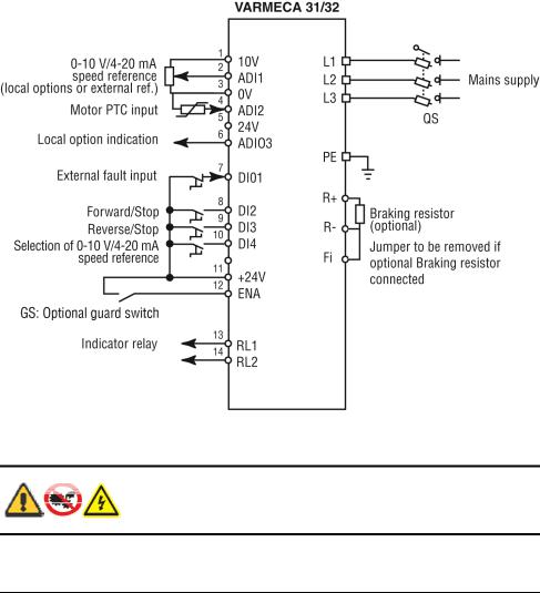
13.5 Varmeca drives: three-phase connection diagram
Note: For single-phase standards, the power supply is connected to terminals L and N.
Before switching on the Varmeca-30 motor, check that electrical connections are correct and that any moving parts are mechanically protected. The Varmeca-30 must not be switched on with the protective cover removed.
13.6 Varmeca drives: keypad indicator light display
Indicator |
Status |
Checks to be performed |
|
|
|
Steady green |
No trip |
|
light |
Mains present |
|
|
|
|
Flashing green |
Current limiting |
Check that the motor is not overloaded or stalled |
light |
|
|
|
|
|
Flashing red |
IGBT temperature |
Check that air can circulate around the motor fins |
light |
alarm |
and Varmeca casing |
|
Motor overload |
The motor is overloaded: check the motor |
|
Braking resistor option |
current using an ammeter |
|
overload |
Check that the deceleration ramp is long enough |
|
|
for applications with high inertia |
|
|
|
Steady red |
Short-circuit of a |
Check that no incident has occurred |
light |
motor winding |
Switch off and on again to clear the fault |
|
Locked motor rotor |
Check the mains voltage |
|
Faulty insulation of a |
Check that the deceleration ramp is long enough |
|
winding |
for applications with high inertia |
|
I²t overheating |
If the fault ramains, consult the manufacturer |
|
Internal fault |
|
|
Undervoltage |
|
|
Overvoltage |
|
|
|
|
file://R:\staging\pdfs-global\m-621cc-gb-04.html |
21/12/2011 |

Watson-Marlow Bredel E-Manuals |
Page 14 of 46 |
13.7 Varmeca drives: Varmeca-30 specifications
Power supply |
Single phase, 208V -10% to 240V +10%, 50/60Hz |
|
±2% |
|
110V -10% to 120V +10%, 50/60Hz ±2% |
|
|
Power range |
0.37kW, 1/2HP |
|
|
Maximum hourly mains |
10 |
stop/starts |
|
|
|
Overload |
150% of nominal current for 60 seconds, 10 times |
|
per hour |
|
|
Efficiency |
97.5% motor efficiency |
|
|
Filter type |
Class B EMC filter (domestic and light industrial level) |
|
|
Motor frequency variation range |
10Hz-80Hz at constant torque |
|
|
Enclosure |
IP65: Varmeca drive; IP55: motor |
|
|
Storage temperature |
-40C to 70C (IEC 68.2.1), -40F to 158F |
|
|
Operating temperature |
-20C to 50C, -4F to 122F; power derated by 1% per |
|
degree C above 40C, 1% per 1.8 degrees F above |
|
104F |
|
|
Altitude |
Up to 1000m without derating |
|
|
UL standard |
Conforming to UL508c (E211799) |
|
|
Weight |
21kg, 46lb |
|
|
file://R:\staging\pdfs-global\m-621cc-gb-04.html |
21/12/2011 |
 Loading...