


 Loading...
Disc
The disc inserted in the front cover contains the user manual of the models Bredel 40, Bredel 50, Bredel 65, Bredel 80 and Bredel 100. The user manual is available in the following languages:
The disc also contains quick-reference instructions for the replacement of the pump hose. This replacement instruction is only for users that are familiar with the replacement procedures in the user manual.
How to use the disc
1Put the disc in the disc drive.
2Close the disc drive.
The disc will start automatically.
3Wait until the various language versions appear on screen.
4Select the required language (click 1x with the left mouse button).
The PDF reader program will automatically start and the required user manual appears on screen.
Shortcuts
In the left margin you will find the various chapters and paragraphs. These can be accessed directly by clicking on the required chapter or paragraph.
In the text you will find hyperlinks to chapters or paragraphs. These hyperlinks are linked with the required chapters or paragraphs. By clicking a shortcut the required chapter or paragraph appears on screen.
System requirements
The program on the disc requires a PC with the following minimum system requirements:
•Disc drive
The following software must be installed on the PC:
•PDF reader program
•An Internet browser
1

2
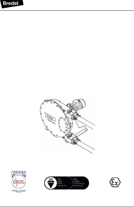
Hose pump series
Bredel 40, Bredel 50, Bredel 65, Bredel 80 and
Bredel 100
Manual
3

© 2013 Watson-Marlow Bredel B.V.
All rights reserved.
The information provided herein may not be reproduced and/or published in any form, by print, photoprint, microfilm or any other means whatsoever (electronically or mechanically) without the prior written authorisation of Watson-Marlow Bredel B.V.
The information provided can be changed without prior notification. Watson-Marlow Bredel B.V. or one of its representatives cannot be held liable for possible damage resulting from use of this manual. This is an extensive limitation of the liability which applies to all damage, inclusive of (without limitation) compensating, direct , indirect or consequential damage, loss of data, income or profit, loss or damage to possessions and claims of third parties.
Watson-Marlow Bredel B.V. provides the information in this manual "as is" and does not take any responsibility and does not give any guarantee on this manual or its content. Watson-Marlow Bredel B.V. rejects all responsibilities and guarantees. Furthermore, Watson-Marlow Bredel B.V. does not take responsibility for and does not guarantee that the information in this manual is accurate, complete or up to date.
Names, trade names, brands, etc. used by Watson-Marlow Bredel B.V. may not, as per the legislation concerning the protection of trade names, be considered as available.
4

CONTENTS |
|
|
|
1 |
GENERAL |
|
|
|
1.1 |
How to use this manual .......................................................................... |
8 |
|
1.2 |
Original instructions ................................................................................ |
8 |
|
1.3 |
Other supplied documentation ................................................................ |
8 |
|
1.4 |
Service and support ................................................................................ |
8 |
|
1.5 |
Environment and disposal of waste ........................................................ |
9 |
2 |
SAFETY |
|
|
|
2.1 |
Symbols ................................................................................................ |
10 |
|
2.2 |
Intended use ......................................................................................... |
10 |
|
2.3 |
Use in potentially explosive atmospheres ............................................. |
11 |
|
2.4 |
Responsibility ........................................................................................ |
11 |
|
2.5 |
Qualification of the user ........................................................................ |
12 |
|
2.6 |
Regulations and instructions ................................................................. |
12 |
3WARRANTY CONDITIONS
4DESCRIPTION
|
4.1 |
Identification of the product ................................................................... |
14 |
|
|
|
4.1.1 Identification of the product ....................................................... |
14 |
|
|
|
4.1.2 Identification of the pump .......................................................... |
14 |
|
|
|
4.1.3 Identification of the gearbox ...................................................... |
14 |
|
|
|
4.1.4 Identification of the electric motor .............................................. |
15 |
|
|
|
4.1.5 Identification of the pump hose ................................................. |
15 |
|
|
4.2 |
Construction of the pump ...................................................................... |
16 |
|
|
4.3 |
Operation of the pump .......................................................................... |
16 |
|
|
4.4 |
Pump hose ............................................................................................ |
18 |
|
|
|
4.4.1 |
General ...................................................................................... |
18 |
|
|
4.4.2 Hose compression force adjustment (shimming) ...................... |
19 |
|
|
|
4.4.3 |
Lubrication and cooling ............................................................. |
19 |
|
4.5 |
Gearbox ................................................................................................ |
19 |
|
|
4.6 |
Electric motor ........................................................................................ |
20 |
|
|
4.7 |
Available options ................................................................................... |
20 |
|
5 |
INSTALLATION |
|
||
|
5.1 |
Unpacking ............................................................................................. |
21 |
|
|
5.2 |
Inspection ............................................................................................. |
21 |
|
|
5.3 |
Installation conditions ........................................................................... |
21 |
|
5

|
|
5.3.1 |
Ambient conditions .................................................................... |
21 |
|
|
5.3.2 |
Set-up ........................................................................................ |
21 |
|
|
5.3.3 |
Pipework ................................................................................... |
22 |
|
5.4 |
Lifting and moving the pump ................................................................ |
23 |
|
|
5.5 |
Placing the pump .................................................................................. |
24 |
|
6 |
COMMISSIONING |
|
||
|
6.1 |
Preparations ......................................................................................... |
25 |
|
|
6.2 |
Commissioning ..................................................................................... |
25 |
|
7 |
MAINTENANCE |
|
||
|
7.1 |
General ................................................................................................. |
26 |
|
|
7.2 |
Maintenance and periodic inspections ................................................. |
26 |
|
|
7.3 |
Cleaning the pump hose ...................................................................... |
28 |
|
|
7.4 |
Changing lubricant ............................................................................... |
28 |
|
|
7.5 |
Changing oil in gearbox ........................................................................ |
29 |
|
|
7.6 |
Replacing pump hose ........................................................................... |
30 |
|
|
|
7.6.1 |
Removing pump hose ............................................................... |
30 |
|
|
7.6.2 |
Cleaning the pump head ........................................................... |
32 |
|
|
7.6.3 |
Fitting the pump hose ................................................................ |
33 |
|
7.7 |
Exchanging replacement parts ............................................................. |
36 |
|
|
|
7.7.1 |
Replacing pressing shoes ......................................................... |
36 |
|
|
7.7.2 |
Replacing seal and wear ring .................................................... |
38 |
|
|
7.7.3 |
Replacing bearings ................................................................... |
41 |
|
7.8 |
Adjusting hose compression force (shimming) ..................................... |
42 |
|
|
7.9 |
Fitting options ....................................................................................... |
45 |
|
|
|
7.9.1 |
Fitting a high-level float switch .................................................. |
45 |
|
|
7.9.2 |
Fitting a low level float switch .................................................... |
47 |
|
|
7.9.3 |
Fitting revolution counter ........................................................... |
47 |
8 |
STORAGE |
|
|
|
|
8.1 |
Hose pump ........................................................................................... |
50 |
|
|
8.2 |
Pump hose ........................................................................................... |
50 |
|
9 |
TROUBLESHOOTING |
|
||
10 |
SPECIFICATIONS |
|
||
|
10.1 |
Pump head ........................................................................................... |
56 |
|
|
|
10.1.1 Performance .............................................................................. |
56 |
|
|
|
10.1.2 Materials .................................................................................... |
57 |
|
6

|
10.1.3 Surface treatment ...................................................................... |
58 |
|
10.1.4 Lubricant table pump ................................................................. |
58 |
|
10.1.5 Weights ..................................................................................... |
58 |
|
10.1.6 Torque figures ........................................................................... |
59 |
|
10.1.7 Shims specifications .................................................................. |
60 |
10.2 |
Lubricant table gearbox ........................................................................ |
61 |
10.3 |
Electric motor ........................................................................................ |
62 |
10.4 |
Parts list ................................................................................................ |
63 |
|
10.4.1 Overview ................................................................................... |
63 |
|
10.4.2 Cover assembly ......................................................................... |
64 |
|
10.4.3 Rotor assembly ......................................................................... |
65 |
|
10.4.4 Pump housing assembly ........................................................... |
66 |
|
10.4.5 Support assembly ...................................................................... |
68 |
|
10.4.6 Flange assembly ....................................................................... |
69 |
|
10.4.7 Revolution counter assembly .................................................... |
70 |
|
10.4.8 Lubricants .................................................................................. |
71 |
7

GENERAL
1 GENERAL
1.1How to use this manual
This manual is intended as a reference book by means of which qualified users are able to install, commission and maintain the hose pumps mentioned on the front cover.
1.2Original instructions
The original instructions for this manual have been written in English. Other language versions of this manual are a translation of the original instructions.
1.3Other supplied documentation
Documentation of components such as motors and inverters is normally not included in this manual. However, if additional documentation is supplied, you must follow the instructions in this additional documentation.
1.4Service and support
For information with respect to specific adjustments, installation, maintenance or repair jobs which fall beyond the scope of this manual, contact your Bredel representative. Make sure you have the following data at hand:
•Serial number hose pump
•Article number pump hose
•Article number gearbox
•Article number electric motor
•Article number frequency controller
You will find these data on the identification plates or stickers of the pumphead, the pump hose, the gearbox and the electric motor. Refer to § 4.1.1.
8

GENERAL
1.5Environment and disposal of waste
CAUTION
Always observe the local rules and regulations with respect to processing (non reusable) parts of the hose pump.
Enquire within your local government about the possibilities for reuse or environment-friendly processing of packaging materials, (contaminated) lubricant and oil.
9
SAFETY
2 SAFETY
2.1Symbols
In this manual the following symbols are used:
WARNING
Procedures which, if not carried out with the necessary care, may result in serious damage to the hose pump or in serious bodily harm.
CAUTION
Procedures which, if not carried out with the necessary care, may result in serious damage to the hose pump, the surrounding area or the environment.
Remarks, suggestions and advice.
WARNING
Procedures, remarks, suggestions or advice which refer to use in potentially explosive atmospheres in accordance with the ATEX Directive 94/9/EC.
2.2Intended use
The hose pump is exclusively designed for pumping suitable products. Every other or further use is not in conformance with the intended use.
The "Intended use" as laid down in EN 292-1 is "... the use for which the technical product is intended in accordance with the specifications of the manufacturer, inclusive of his indications in the sales brochure". In case of doubt it is the use which appears to be its intended use judging from the construction, execution
10
SAFETY
and function of the product. Observing the instructions in the user's documentation also belongs to intended use.
Only use the pump in conformance with the intended use described above. The manufacturer cannot be held responsible for damage or harm resulting from use that is not in conformance with the intended use. If you want to change the application of your hose pump, contact your Bredel representative first.
2.3Use in potentially explosive atmospheres
The pump head and gearbox mentioned in this manual are suitable for use in a potentially explosive atmosphere. Use in Potentially explosive atmospheres requires special configuration of the pump unit (See 4.7). The pumps mentioned meet the requirements as stated in the European Directive 94/9/EC (ATEX Directive).
The pumps belong to:
•Group II Appliances, category 2 G ck T4
2.4Responsibility
The manufacturer does not accept any responsibility for damage or harm caused by not (strictly) observing the safety regulations and instructions in this manual and the also supplied documentation, or by negligence during installation, use, maintenance and repair of the hose pumps mentioned on the front cover. Depending on the specific working conditions or accessories used, additional safety instructions can be required.
11

SAFETY
Immediately contact your Bredel representative, if you noticed a potential danger while using your hose pump.
WARNING
The user of the hose pump is always fully responsible for observing the local valid safety regulations and directives. Observe these safety regulations and directives when using the hose pump.
2.5Qualification of the user
The installation, use and maintenance of the hose pump should only be performed by well-trained and qualified users. Temporary staff and persons in training may use the hose pump only under the supervision and responsibility of trained and qualified users.
2.6Regulations and instructions
•Everyone who works with the hose pump must be aware of the contents of this manual and observe the instructions with great care.
•Never change the order of the actions to be carried out.
•Always store the manual near the hose pump.
12

WARRANTY CONDITIONS
3 WARRANTY CONDITIONS
The manufacturer offers a two-year warranty on all parts of the hose pump. This means that all parts will be repaired or replaced free of charge, with the exception of consumables, such as pump hoses, hose clamps, ball bearings, wear rings, and seals, or parts which have been misused or have been intentionally damaged.
If parts are used that are not Watson-Marlow Bredel B.V. (hereafter called Bredel) parts, every warranty becomes void.
Damaged parts which are covered by the applicable warranty conditions can be returned to the manufacturer. The parts must be accompanied by a fully filled in and signed safety form, as present in the back of this manual. The safety form must be applied to the outside of the shipping carton. Parts which have been contaminated or which have been corroded by chemicals or other substances which can pose a health risk, must be cleaned before they are returned to the manufacturer. Furthermore, it should be indicated on the safety form which specific cleaning procedure has been followed, and it should be indicated that the equipment has been decontaminated. The safety form is required at all items, even if the parts have not been used.
Warranties purporting to be on behalf of Bredel, made by any person, including representatives of Bredel, its subsidiaries, or its distributors, which do not accord with the terms of this warranty shall not be binding upon Bredel unless expressly approved in writing by a Director or Manager of Bredel.
13
DESCRIPTION
4 DESCRIPTION
4.1Identification of the product
4.1.1Identification of the product
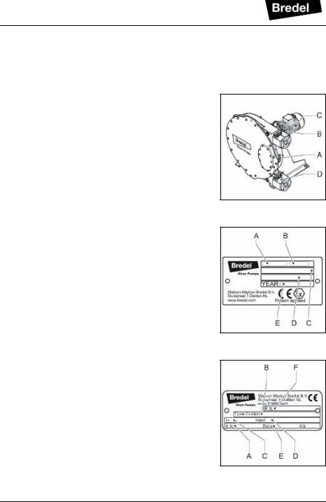
The hose pump can be identified based on the identification plates or stickers on:
A:Pump head
B:Gearbox
C:Electric motor
D:Pump hose
4.1.2Identification of the pump
The identification plate on the pump head contains the following data:
A:Type number
B:Serial number
C:ATEX code
D:ATEX document number
E:Year of manufacture
4.1.3Identification of the gearbox
The identification plate on the gearbox contains the following data:
A:Serial number (S.N.)
B:Type number (Type/Output)
C:Reduction (i=)
D:Input (adaptation of the motor to the gearbox)
E:Date
F:Bredel article or order number (PN)
14
DESCRIPTION
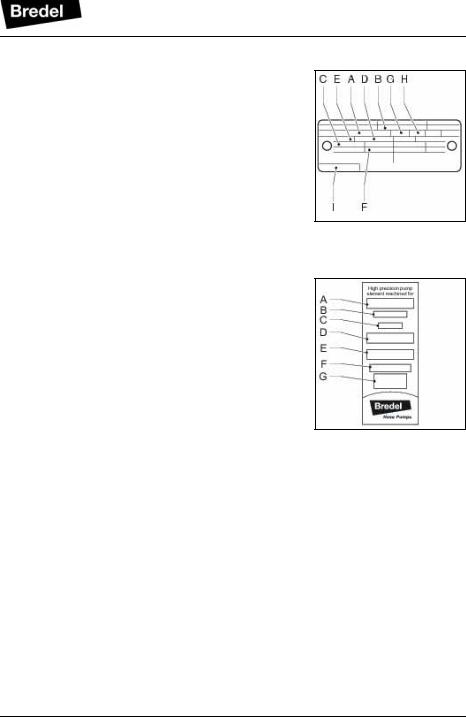
4.1.4Identification of the electric motor
The identification plate on the electric motor contains the following data:
A:Serial number
B:Type number
C:Power
D:Voltage
E:Frequency
F:Speed
G:Insulation class
H:Protection class
I:Bredel article or order number
4.1.5Identification of the pump hose
The identification sticker on the pump hose contains the following data:
A:Pump type
B:Reorder number
C:Internal diameter
D:Type of material of inner liner
E:Remarks, if applicable
F:Maximum permissible working pressure
G:Production code
15
DESCRIPTION
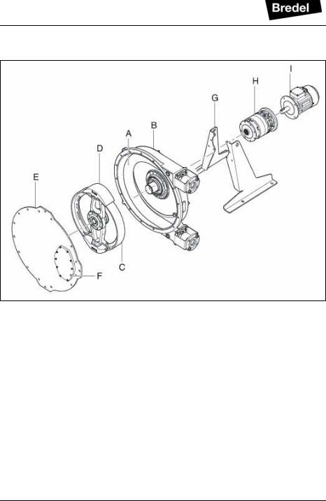
4.2Construction of the pump
A:Pump hose
B:Pump housing
C:Rotor
D:Pressing shoes
E:Cover
F:Inspection window
G:Supports
H:Gearbox
I:Electric motor
4.3Operation of the pump
The heart of the pump head consists of a specially constructed pump hose (A) which lies contorted against the inside of the pump housing (B). Both ends of the hose are connected to the suction and discharge lines
16
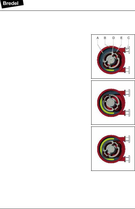
DESCRIPTION
by means of a flange construction (C). A bearingmounted rotor (D) with two facing pressing shoes (E) is in the centre of the pump head.
In phase 1 the lower pressing shoe compresses the pump hose by the rotational movement of the rotor, forcing the fluid through the hose. As soon as the pressing shoe has passed, the hose recovers to its original shape due to the mechanical properties of the material.
In phase 2 the product is drawn into the hose by the (continuous) turning motion of the rotor.
In phase 3, the second pressing shoe will subsequently compress the pump hose. Due to the continuous rotating movement of the rotor not only new product is sucked in, but also the already present product is pressed out by the pressing shoe. When the first pressing shoe runs from the pump hose, the second pressing shoe has already closed the pump hose and the product is prevented from flowing back. This method of liquid displacement is also known as the "positive displacement principle".
17
DESCRIPTION
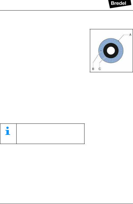
4.4Pump hose
4.4.1General
A:Outer extruded layer made of natural rubber
B:Four nylon reinforcement layers
C:Inner extruded liner
The pump hose liner material should be chemically resistant with the product to be pumped. Dependent on the specific requirements of your application a corresponding pump hose must be selected. For each pump model various hose types are available.
The material of the inner liner of the pump hose determines the hose type. Each hose type is marked by a unique colour code.
Hose type |
Material |
Colour code |
NR |
Natural rubber |
Purple |
|
|
|
NBR |
Nitrile rubber |
Yellow |
|
|
|
EPDM |
EPDM |
Red |
|
|
|
CSM |
CSM |
Blue |
|
|
|
Consult your Bredel representative for more detailed information about the chemical and temperature resistance of pump hoses.
The Bredel pump hoses have been carefully machined, therefore there are minimum tolerances in wall thickness. It is very important to guarantee the correct compression of the pump hose, because:
•When the compression is too high, it creates a too high load of the pump and pump hose, which may result in a reduction of the life of the pump hose and bearings.
•When the compression is too low, this will result in loss of yield and backflow. Backflow results in a reduction of the life of the pump hose.
18
DESCRIPTION
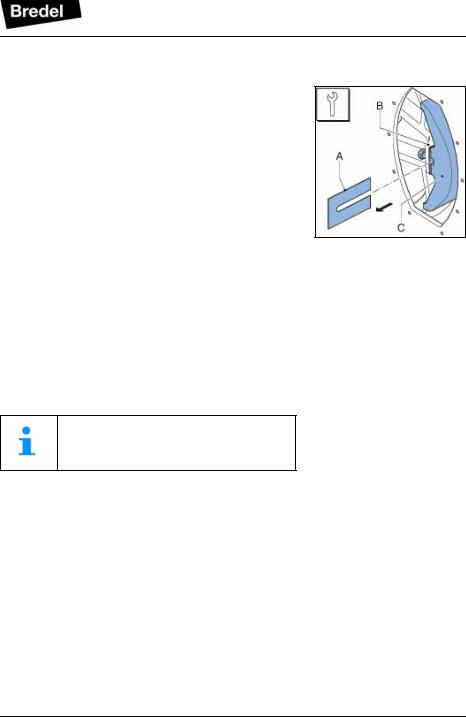
4.4.2Hose compression force adjustment (shimming)
In order to achieve optimal life of the pump hose, the compression force of the pump hose can be adjusted by placing a number of shims under the pressing shoes. The shims (A) are fitted between the rotor (B) and the pressing shoe (C). The number of shims will vary for each counterpressure situation.
The paragraph 7.8 describes how to select and install the shims.
4.4.3Lubrication and cooling
The pumphead, in which the rotor and pump hose can be found, is filled with Bredel Genuine Hose Lubricant. This lubricant lubricates the movement between the hose and the pressing shoes and dissipates the generated heat via the pump housing and the cover.
The lubricant is food grade. See § 10.1.4 for the required quantity and NSF registration.
Consult your Bredel representative for lubrication recommendations when operating the hose pump below 2 rpm.
4.5Gearbox
The hose pump types described in this manual use planetary gearbox units. The gearbox units are characterized by their compact and modular construction.
This modular construction enables a wide range of reductions, torques and connection possibilities for the electric motor.
19

DESCRIPTION
4.6Electric motor
If the electric motor has been standard supplied by the manufacturer, it is a standardized squirrel-cage motor. Refer to § 10.3 for specifications. If the pump is to be used in potentially explosive atmospheres, contact your Bredel representative.
4.7Available options
The following options are available for the hose pump:
•High (lubricant) level float switch
•Low (lubricant) level float switch
•Revolution counter
•Adapter for heavy duty drive (Bredel 65 and Bredel 80 only)
The high level float switch is mandatory for use in potentially explosive atmospheres. If the pump is to be used in potentially explosive atmospheres, contact your Bredel representative.
20
INSTALLATION
5 INSTALLATION
5.1Unpacking
When unpacking carefully follow the instructions as given on the packaging or on the hose pump.
5.2Inspection
Check that your delivery is correct and check it for any transport damage. Refer to § 4.1.1. Report any damage immediately to your Bredel representative.
5.3Installation conditions
5.3.1Ambient conditions
Make sure that the hose pump is in an area where the ambient temperature during operation is not lower than -20 °C and not higher than +45 °C.
5.3.2Set-up
•
•
•
•
The pump materials and protective layers are suitable for indoor set-up and a protected outdoor set-up. Under certain conditions the pump is suitable for limited outdoor set-up or a salty or aggressive atmosphere. Consult your Bredel representative for more information.
Make sure that the floor surface is horizontal and has a maximum slope of 10 mm per metre. Make sure that there is sufficient room around the pump to carry out the necessary maintenance activities.
Make sure that the room is sufficiently ventilated, so that the heat developed by the pump and drive can be discharged. Keep some distance between the ventilation cover of the electric motor and wall to enable the supply of necessary cooling air.
21
INSTALLATION
5.3.3Pipework
When determining and connecting suction and discharge lines consider the following points:
•The bore size of the suction and discharge lines must be larger than the bore size of the pump hose. For more information consult your Bredel representative.
•Limit the presence of sharp bends in the discharge line. Make sure that the radius of the bent discharge line is as large as possible (preferably 5S). It is recommended to use Y- connections instead of T-connections.
•Keep the piping at a minimum equal to or greater than the bore size of the pump. Increase the bore size of the pipe work when the duty fluid has a high velocity or inertia. This will help keep friction and impulse losses to a minimum. Where critical velocities are a concern consult your Bredel representative.
•For the flexible hoses select compatible materials and ensure the installation is suited for the design pressure of the system.
•Keep the delivery and suction lines as short and direct as possible.
•Prevent any possibilities of exceeding the maximum working pressure of the hose pump. Refer to § 10.1.1. If necessary fit a pressure relief valve.
CAUTION
Consider the maximum permissible working pressure on the discharge side. Exceeding the maximum working pressure may lead to serious damage to the pump.
•Make sure that the maximum forces on the flanges are not exceeded. The permissible loads are given in the following table.
22

INSTALLATION
Maximum permissible loads [N] on the pump flange
Force |
Bredel |
Bredel |
Bredel |
Bredel |
Bredel |
|
40 |
50 |
65 |
80 |
100 |
|
|
|
|
|
|
F1 |
1000 |
1400 |
1400 |
2000 |
2000 |
|
|
|
|
|
|
F2 |
200 |
300 |
300 |
400 |
400 |
|
|
|
|
|
|
F3 |
500 |
700 |
700 |
1000 |
1000 |
|
|
|
|
|
|
5.4Lifting and moving the pump
For lifting and moving the pump, it has been fitted with a lifting point. This lifting point (A) is fitted on the upper side of the cover. The maximum rating of the lifting point depends on the pump model. Make sure that the total of weight to be moved will not exceed this maximum rating.
For the weights, refer to § 10.1.5.
Maximum rating of the lifting point of the pump head
Bredel |
Bredel |
Bredel |
Bredel |
Bredel |
40 |
50 |
65 |
80 |
100 |
|
|
|
|
|
200 kg |
390 kg |
670 kg |
1020 kg |
1580 kg |
|
|
|
|
|
The complete hose pump, i.e. pump head, gearbox and electric motor, must be lifted using the lifting point of the pump head plus additional support using suitably rated straps or slings (A). Never exceed the maximum rating of the lifting point of the pump head.
WARNING
If the pump is to be lifted ensure that all standard lifting practices are adhered to and carried out by qualified personnel only.
23
Loading...