


Union Special 61400A, 61400B, 61400E, 61400F, 61400G Manual
...
Catalog No. 83 R
LIST OF PARTS AND INSTRUCTIONS
FOR
ADJUSTING AND· OPERATING
|
|
Class 61400 |
|
|
|
Streamlined Lockstitch |
|
|
|||
|
|
Styles |
|
|
|
61400 A |
|
|
61400 |
J |
|
61400 |
B |
|
61400 |
N |
|
61400 |
E |
|
61400 |
p |
|
61400 |
F |
61400 |
R |
|
|
61400 |
G |
61400 s |
|
|
|
61400 H |
·61400AA |
|
|||
|
|
61400 |
BA |
|
|
Third Edition
Copyright 19 55
By
Union Special Corporation
Rights Reserved in All Countries
CORPORATION
INDUSTRIAL SEWING MACHINES
CHICAGO
Printed in U.S.A.
November, 1974
3
From the library of: Superior Sewing Machine & Supply LLC
FOREWORD
The dominating idea back of "Union Special" is to build the best industrial sewing machines in the world. The new high speed Streamlined Lockstitch machines are a pronounced achievement along these lines. All parts are made to precision gauges insuring complete interchangeability. A few of the outstanding new features are:
1.Streamlined design. Pleasing in appearance, this natural functional design provides greater stability and ruggedness, free from difficult-to-clean recesses.
2.Simplified oiling. Automatically supplies oil to lower main shaft bearings, feed rocker and feed lift bearings and not only eliminates all oil holes in cloth plate but also does away with hand lubrication commonly required below bed plate.
3.Acceleration. The new Streamlined Lockstitch is brought to top
speed in an instant - for higher productive rates and lower costs.
4. Push button control, for quick, easy adjustment of stitch length. With a stitch length indicator of the comparison type, using letters as a means of reference to predetermine stitch lengths.
It is our constant aim to furnish carefully prepared information that will enable the customer to secure all possible economies and advantages from the use of Union Specials. The following pages contain valuable operating and adjusting data and illustrate and describe the parts for Styles in Class 61400 Streamlined Lockstitch machines.
An additional catalog, containing information relative to these machines, and which will be furnished on request, is listed below:
Catalog No. 45 N |
Needle Manual |
Union Special representatives will be found in all manufacturing centers, ready to cooperate with you to plan and estimate requirements.
CORPORATION
Engineering Department
From the library of: Superior5Sewing Machine & Supply LLC


INSTRUCTIONS FOR ASSEMBLING ACCESSORIES 29480 AJ' OR 29480 CG ~ISOLATORS ZS480AK ONTO TABLEBOARD.S 21371NB 1 ZI.371NO (ALL LENGTHS)
TABLe BOARD
21371 NB-42,-4B~-s4,-6o
21371 N0-42,-48;-541 60
NOTE.;
PART
END OF 150/...ATORS
MAY BE. rRIMMED
70 BRING CLOTH
PLATE FLUSH WITH TABLE. BOARO
ASSEMBLY
|
NS 61471M |
|
666 - IG6 |
il-lal~~===::::::::2:_____ 21.3 9 3 F |
|
POSITION OIL PAN BY NA /LING |
SC 32.9A 21662 C |
|
|
AT1?/MPLES IN ~~D.PROPER
POSITION PROVIDES DRAINING
TO !He RIGHT FI<'OIVTCCY<NER
ASSEMBLY
NR21660C
PERIMETER Or
BED MUST CONTACT rHE TWO LEATHER
ISOLATORS ONLY.
IF BED CONTACTS
BOARA VIBRA-
TION WILL BE
TRANSMITTED
THE TWONAILS SECUR/NGL.EATHER
ISOLATOR TO TABLE BOARO
MVST Be LOW ENOVGH TO
CLEAR BED
:ttc 2.13S3 T INCLUDED WITH 2!1480 CG FOR 61.900 WITH PINKER
-9-
From the library of: Superior Sewing Machine & Supply LLC

INSTALLING
Each machine before it leaves the factory is sewed off, inspected, and carefully packed. When the machine reaches the customer it is ready for service. Because o~ all the precaution taken by those who handle the machine, the customer needs only to place it in its proper position in the table and make only the ordinary settings to adapt the machine to the material he wishes to sew.
ASSEMBLY PARTS
A bag of assembly parts, consisting of one spool pin, one extra bobbin, two hinge studs, and two screws for holding miscellaneous attachments to the bed plate is packed with each machine.
After unpacking the machine assemble the spool pin (K, Fig. 3).
Push the hinge studs into position in the holes provided at the rear of the machine. The studs are slotted so that a tight fit can be easily made.
STANDARD ACCESSORIES
Also included with each machine is a box of standard accessories containing one bobbin winder assembly, one drip pan, one oil drain jar and clamp spring, one knee lifter assembly and rubber pad, one machine rest pin, two hinge plates and screws, four felt pads and necessary nails. These parts are indispensable when setting up the machine.
TABLE TOPS
Lockstitch machines are installed in table tops prepared with cut out, so that the bed plate is flush with the top of the table.
Standard table tops are available for isolated mounting on all types of installations and drives.
Isolated mounting parts are not included with table tops and must be ordered separately. The installation of isolated mounting parts is shown in (Fig. 1). For table tops not prepared for isolated mounting, felt pads are furnished with the accessories for isolating. The nails for these pads should be driven horizontally as indicated on the right end of cut-out (Fig. 1).
When assembling the hinge plates to the table tops, be sure to locate them as accurately as possible, so that the hinge studs, attached to the machine, can swing properly in the plate.
Special care should be taken that machine does not contact the sides of the cut-out at any point.
KNEE PRESS
The knee press is attached to Union Special table tops at the location designated by punch marks on the underside. For other boards locate the knee press so that the center of the shaft is 8-1/4 inches from the right side of the cut-off. The knee press assembly should appear as in (Fig. 2).
DRIP PAN
The drip pan is attached to Union Special table tops at the indentation marks on the inside of the cut-out, using the nails furnished with the accessories (Fig. 1). For other table tops, the drip pan should be set high enough to clear the knee press and low enough to clear the botton of the machine. It should be laterally located so that it is directly under the base of the machine.
Fig. 2
-10-
From the library of: Superior Sewing Machine & Supply LLC

F'tLL MAIN
R£StRVot~ HE"R£
Fig. 3
-11 ..
From the library of: Superior Sewing Machine & Supply LLC
INSTALLING (Continued)
BOBBIN WINDER
The bobbin winder should be secured to the table top so that its pulley will be located directly in front of the sewing machine belt and will bear against the belt when in operation. The base of the winder has two elongated attaching holes, which allows the mechanism to be moved closer to or farther away from belt as needed. The pulley of the winder, when in operation should exert only enough pressure against the belt to wind the bobbin. Re~ulation and operation of the bobbin winder is described under "Threading and Winding the Bobbin '.
BELTS
These machines are equipped to use either No. 1 "V" or round belt.
LUBRICATION
CAUTION!!
The oil has been drained from the main reservoir, the hook shaft gear case, and the hook oil reservoir before shipment and these reservoirs must be filled before starting to operate. Lubricate machine thoroughly in accordance with instructions and run slowly for several minutes to distribute the oil to the various parts. Full speed operation can then be expected without damage.
RECOMMENDED OILS
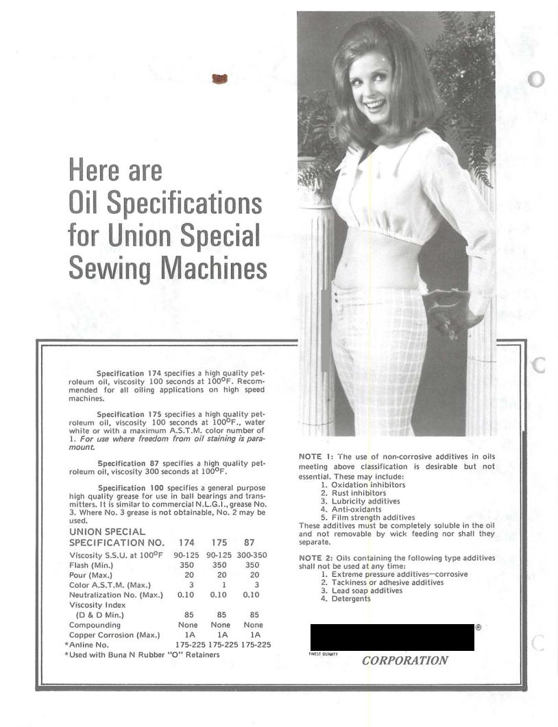
Use a straight mineral oil of a Saybolt viscosity of 90 to 125 seconds at 100° F. in hook oil reservoir, main reservoir, and hook shaft gear case. This is equivalent to Union Special oil specification No. 174.
Stainless water white straight mineral oil of the same viscosity as that described in the preceding paragraph can be used in the hook oil reservoir, the stainless oil is Union Special specification No. 17&.
Oils conforming to spec~fication No. 174 or 175 may also be used in the manually oiled places.
For trouble free operation, oil the machine as indicated in the diagram (Fig. 3).
With needle bar at the top of its stroke, oil the holes (A) twice daily. In oiling hole (B), very little oil sllould be used and only around the outer edges of the needle bar. Do not put oil into the hole in the needle bar as it will flow out when machine is operated at high speed. A can of oil, No. 28604 J, is included with the accessories packed with the machine. It contains a sufficient quantity to fill all the reservoirs. The main reservoir is filled through oil cup (C) and the supply is usually replenished about twice a month. However, the oil level should be checked from time to time'and kept between the lines on the gauge (D).
Th"e hook oil reservoir is filled at plug screw (E) and its level should be checked twice daily and kept between the lines on the gauge (F).
The hook shaft gear case is filled at the plug screw hole (L). A quantity of oil sufficient to bring the level up to the plug screw hole, when the machine is tilted back against the rest pin, should be used. Remove plug screw and check the level of oil about every six months.
On Styles 61400 N, 61400 P, 61400 R, 61400 S, holes (M) should be oiled sparingly each day. CAUTION! I
Do not use a compounded oil in the hook oil reservoir, feeding drive shaft gear case, or hook shaft gear case, as these oils separate and froth.
·t
-12-
From the library of: Superior Sewing Machine & Supply LLC

LUBRICATION (Continued)
CAUTION!!
A
Fig. 5
TYPE NUMBERS AND SIZES
Lubrication of the mechanism below the bed plate is automatically accomplished through the feed driving shaft which is tubular. Oil is introduced into the shaft at the gear end by means of an oil distributing plate (A, Fig. 5) which is secured to the large gear case cover (B) by means of two screws (C) and retaining block (D).
Should it ever become necessary to remove any of the parts from the gear case, it is imperative that the adjustment of the oil distributing plate be checked very carefully.
0 This can be done by removing the large plug screw at the right end of the gear housing and looking through the hole. The low point of the oil distributing plate must be even with or slightly below the center of shaft (E) and just touching it. This is a very important adjustment as the functioning of the automatic lu-. brication of the lower part of the machine depends upon it.
NEEDLES
Each needle has a type number and size number. The former denotes the kind of shank, point, length of groove, finish and other details. The latter denotes the largest diameter of the blade, measured in thousandths of an inch across the eye, and is stamped in the needle shank. Collectively, the type number and the size number is the complete symbol.
To h?-ve orders promptly and accurately filled, the empty package, |
a sample needle, |
or the |
||||||
type and S1ze number should be given. See marks on packages. A complete order would read as |
||||||||
follows: |
"1000 Needles Type 183 GXS, Size 040". |
|
|
|
|
|||
Needle Types 180 GXS or 180 GYS are recommended for Styles 61400 B, |
61400 R, 61400 S. |
|||||||
Needle Types 183 GXS, 183 GYS are recommended for Styles 61400 A, 61400 E, 61400 F |
61400 G |
|||||||
61400 H, |
61400 N. |
61400 P. |
|
|
|
I |
|
I |
TYPE NO. |
|
|
DESCRIPTION AND SIZES |
|
|
|
|
|
180 GXS |
Lockstitch, |
short length, ball eye, single groove, |
wide angle groove, |
struck |
||||
|
|
groove, deep spot, |
ball point, chromium plated - |
sizes • 028, • 032, |
. 036, • 040, |
|||
|
|
• 044, • 048, |
• 054, |
• 060. |
|
|
|
|
180 GYS |
Lockstitch, |
short length, ball eye, single groove, |
wide angle groove, |
struck |
||||
|
|
groove, deep spot, |
chromium plated - sizes • 028, |
. 032, |
• 036, • 040, |
• 044, |
||
|
|
• 048, • 054, |
• 060. |
|
|
|
|
|
183 GXS |
Lockstitch, |
extra short length, ball eye, single groove, |
wide angle groove, |
|||||
|
|
struck groove, deep spot, ball point, chromium plated - |
sizes • 028, |
|
• 032, • 036, |
|||
|
|
• 040, • 044. |
|
|
|
|
|
|
183 GYS |
Lockstitch, |
extra short length, ball eye, single groove, |
wide angle groove, |
|||||
|
|
struck groove, deep spot, chromium plated - sizes • 028, • 032, • 036, • 040, |
||||||
|
|
• 044. |
|
|
|
|
|
|
SELECTING THE SIZE OF THE NEEDLE
The strength requirement of the seam produced is largely dependent on the size of the thread employed. The quality of the work desired is largely dependent on the size of the needle employed. On heavy work, the penetration of which requires a sturdy needle, it is advisable to use a comparatively large size needle for a given size .thread.
The following table shows the preferred size of needle for a given size and kind of thread. The choice, however, should give consideration to the factors referred to above, which may dictate the selection of a needle size slightly larger or smaller than the size specified.
-13-
From the library of: Superior Sewing Machine & Supply LLC

|
|
NEEDLES (Continued) |
|
|
|
|
||
SELECTING THE SIZE OF THE NEEDLE (Continued) |
|
|
|
|
||||
COTTON |
MERCERIZED |
|
NEEDLE f |
|||||
THREAD SIZE |
THREAD SIZE |
|
SIZE |
|||||
20____________________________ |
|
|
|
|
060 |
|
||
30 |
|
|
B ------------------- 054 to 060 |
|||||
36 |
|
|
A |
048 |
to 054 |
|||
40 |
|
|
A |
044 |
to 048 |
|||
50 |
|
0 |
|
044 |
to 048 |
|||
60 |
|
00 |
|
|
040 to 044 |
|||
70 |
|
000 |
|
036 |
to 040 |
|||
80 |
|
0000 |
|
032 |
to 036 |
|||
90 |
|
0000 |
|
032 |
to 036 |
|||
100 |
|
|
|
|
|
028 |
to 032 |
|
OPERATOR'S INSTRUCTIONS
THREAD
While the direction of the twist in the bobbin thread is immaterial, the direction the hook rotates favors the use of a left twist thread in the needleo To determine the direction of twist grasp a short length of thread between the thumb and forefinger of both handso Turn the thread away from you with the right hando H the strands unwind it is a left twist; if the strands wind tighter it is a right twisto
SELECTING THE HOOK ASSEMBLY
Due to variations For sizes 30-4 to 16-4 smaller than 30-4 No.
in the sizes of needle thread used, two hook assemblies have been provided. thread, the use of Noo L628 hook assembly is recommended and for sizes 29474 F should be usedo
REMOVING THE BOBBIN CASE |
( |
To remove the bobbin case, turn handwheel in operating direction |
|
until the needle reaches its highest position. Using the left hand reach |
|
under the table, open the bobbin case latch (A, Fig. 6) and pull the |
|
bobbin case out of the sewing hook. |
|
Opening the latch retains the bobbin in the caseo When the latch |
|
is closed the bobbin is released and can readily be removedo |
|
WINDING THE BOBBIN |
|
Thread the bobbin winder by leading the thread from the supply |
Figo 6 |
down through the eyelet (A, Fig. 7), down between the tension discs, and under the tension post. Press an empty bobbin on the winder
shaft (B) up to the stop, wind the end of thread around the bobbin a few turns in a clockwise direction, and press downwardly on hand lever (C) until pulley is moved into contact with machine belt, and is locked in that position. When the machine is operated, the bobbin will be rotated and filled until the thread engages the automatic throw-out member, which disengages the pulley. The extent to which the bobbin is filled can be varied by regulating the screw (D).
The tension post bracket is mounted on the winder base, and can be shifted from left to right by loosening screw (E) so that any tendency of the bobbin to wind unevenly may be readily corrected.
-14-
From the library of: Superior Sewing Machine & Supply LLC

OPERATOR'S INSTRUCTIONS (Continued)
WINDING THE BOBBIN (Continued)
The purpose of the bobbin winder is to assure the operator of a full bobbin at all times. When the bobbin in the machine is used up, replace it with a full one and begin to wind the empty bobbin immediately. Bobbins can be rewound while the machine is sewingo
Fig. 7
THREADING THE BOBBIN CASE
The bobbin case should be held between the thumb, second and third fingers of the left hand
(A, Fig. 8).
The bobbin should be held between the thumb and forefinger of the right hand (B) with the thread coming off the bottom of the bobbin.
|
Place the bobbin in the bobbin |
|
|
case. In one continuous motion with |
|
|
the thumb and forefinger of the right |
|
|
hand draw the bobbin thread through |
|
|
the diagonal slot in bobbin case (A, |
|
|
Fig. 9) under the tension spring and |
|
|
into corner of spring (B). Note the |
|
|
direction of the rotation of the bobbin |
|
|
as the end of the thread is pulled when |
|
|
looking at the bobbin case from the |
|
Fig. 8 |
back. The bobbin should rotate coun- |
|
terclockwise. |
Fig. 9 |
REPLACING THE BOBBIN CASE
Have the needle bar at its highest position, allow about two and one half inches of thread to hang free. The bobbin case latch should be opened with the left hand and by reaching under the table and through the opening in the table it should be placed part way into the sewing hook. The latch should then be released and bobbin case snapped into position.
INSERTING THE NEEDLE
Insert the needle in the needle bar as far as it will go, with the spot or scarf toward the right facing the handwheel. Tighten the set screw securely.
The cross hole in needle bar, about 1/4 inch from end (A, Fig. 10) is to show the operator when the needle has been inserted as far up as it will go, and to provide a means for cleaning accumulated lint from needle hole so needle will seat properly.
Fig. 10
-15-
From the library of: Superior Sewing Machine & Supply LLC

OPERATOR'S INSTRUCTIONS (Continued)
THREADING THE NEEDLE
Threading diagram (Figo 3) shows the places where the needle thread passes. Please note that the needle thread passes through the needle eye from left to right.
PREPARATION FOR SEWING
With the left hand hold the end of the needle thread, leaving it slack, and turn the handwheel in operating direction until the needle moves down and up again to its highest position. Pull up the needle thread and the bobbin thread will come up with it through the needle hole in throat plateo Draw both threads under the presser footo
TENSIONS
A perfect stitch is one in which the needle thread and bobbin thread are locked together in the center of the material being sewed. A stitch of this kind is secured by regulating the tensions on both threads.
BOBBIN THREAD TENSION
The tension on the bobbin case is applied by means of a set screw (A, Fig. 11) which regulates tension spring (B). The tension on the spring is correct when it is just sufficient to hold the case and bobbin, suspended by the bobbin thread.
Remove the bobbin case from the bobbin case holder and turn set screw in spring in a clockwise direction to apply more tensions or counterclockwise to release tension.
When the bobbin thread tension is correct it rarely becomes necessary to make any changes as varying the needle thread tension will usually attain a good stitch.
NEEDLE THREAD TENSION
The needle thread tension is varied by turning the tension regulating nut (G, Fig. 3). Turning the nut in a clockwise direction increases the tension and counterclockwise decreases the tension.
This should not be done when the presser foot is in its raised position, and is generally done while the machine is sewing on a piece of scrap material.
TO CHANGE THE STITCH LENGTH
Press plunger (H, Fig. 3) in firmly. While holding plunger in, turn handwheel in op~ra~ng
direction until stitch regulating finger is felt to drop into the slot of feed eccentric. Continuing to hold the plunger in, turn handwheel in operating direction to increase the stitch length and in opposite direction to decrease
the stitch length.
Comparative stitch lengths are indicated by the graduations on the dial (1) in bed plate, ranging from S (Short) to L (Long). Release the plunger.
|
PRESSURE ON MATERIAL |
|
The presser spring should exert only enough pressure to |
|
make the work feed uniformly. To increase the pressure on the |
|
presser foot turn the presser spring regulator (A, Fig. 12) in |
|
clockwise direction. Turning the regulator counterclockwise |
Fig. 12 |
decreases the pressure. |
-16-
From the library of: Superior Sewing Machine & Supply LLC

MECHANIC'S INSTRUCTIONS
SETTING THE NEEDLE BAR TO HEIGHT
The lower needle bar bushing, the one to which the needle bar is timed, is set at the factory, the distance from the bottom of bushing (B, Fig. 13) to the throat plate seat is 2-9/32 inches.
The four lines engraved on the needle bar are used in
setting the bar to height and are referred to as timing lines. |
|
The upper two lines are used with the extra short length Type |
|
183 GC or 183 GL needles which are recommended for Styles |
|
61400 A, 61400 E, 61400 F, 61400 G, 61400 H, 61400 N, |
|
61400 P. |
D |
|
|
The lower two lines are used with the short length Type |
|
180 GL needles which are recommended for Styles 61400 B, |
|
61400 R, 61400 S. |
|
When the needle bar is at its lowest position the upper |
|
timing line (A) of the pair selected, dependent on the needle |
|
being used, should be even with the lower edge of the lower |
|
needle bar bushing (B). To change the position of the needle |
|
bar turn the handwheel until the needle bar is at its lowest |
|
position, then loosen clamp screw (D) and move the bar to the |
|
proper timing line. Keeping the needle bar link at its lowest |
Fig. 13 |
position, retighten screw securely. |
The illustration (Fig. 13) shows the proper setting of the needle bar on Style 61400 A using extra short needles Types 183GNS or 183GPS. The setting of the needle bar on Style 61400 B using short needles Types 180GNS or 180GPS is accomplished in the same manner except that the lower pair of timing marks on the needle bar is used.
TIMING THE HOOK |
|
|
Tip the machine back so that it rests on the rest pin |
|
in the table top. Insert a new needle. Loosen the two |
|
screws and swing out the bobbin case positioning finger |
|
(B, Fig. 14). Loosen the three set screws (A) in the hook |
|
and hold the hook and bobbin case holder in such a position |
|
as to prevent interference with the needle. Tum the hand- |
|
wheel in operating direction until the needle bar is at its |
|
lowest position, continue to turn the handwheel until the |
|
needle is ascending and the lowest timing mark of the pair |
|
used {C, Fig. 13) in setting the needle bar is even with the |
|
lower edge of the needle bar bushing (B). |
|
Turn the hook on the shaft until the point of the hook |
|
is even with the center of the needle and as close to the |
|
needle as possible without deflecting it. A spacing of .003 |
|
to .005 inch between |
|
the needle and the |
Fig. 14 |
point of the hook |
is satisfactory. |
|
|
With the hook in |
|
this position, |
tighten the set screw opposite the hook point securely. Then tighten two remaining screws securely and recheck the timing of hook with the needle at which time the top of the eye of the needle should be about 1/64 inch below the bottom of the hook point. If this condition does not exist, recheck the setting of the needle bar bushing in relation to the throat plate seat.
Adjust the bobbin case holder positioning finger by |
|
turning the bobbin case holder until the finger recess is |
|
at the top.. Place the projection on the finger into the |
|
bobbin case holder recess and tighten the finger attach- |
|
ing screws securely, allowing 1/32 inch clearance between |
|
the outside edge of projection and inside edge of bobbin |
Fig. 15 |
case recess (Fig. 15). |
-17-
From the library of: Superior Sewing Machine & Supply LLC

MECHANIC'S INSTRUCTIONS (Continued)
HOOK LUBRICATION
Insert the bobbin case in the hook and run the machine. CAUTION! Do not run the machine without the bobbin case in the hook, as hook damage may result. After a minute of running, place a piece of white paper directly below the hook, continue running the machine, check the delivery of oil from the hooko The hook is properly lubricated when a definite pattern of oil appears on the test paper after a five second runo
Running through the middle of the hook shaft is an oil metering insert pin which controls the flow of oil to the hooko An occasional cleaning of this insert pin will insure its proper operationo
To withdraw the pin from the hook shaft, the hook must first be removedo The end of the insert pin has an internal thread into which Union Special metering_pin extractor No. 21227 AZ may be screwed and the pin withdrawno
The metering insert pin should fit snugly in the hook shaft. Hit is loose it should be withdrawn and kinked slightlyo
When re-assembling the hook it must be re-timed as previously instructedo
HOOK SHAFT
Should it become necessary to replace the hook shaft, drain the oil from the gear case and remove gear case cover and hooko Loosen gear set screws (A, Fig. 16) and carefully withdraw hook shafto Remove thrust collar from left end of hook shaft by loosening screws (B). Tore-
assemble, slide collar onto the hook shaft with f~ced end adjacent to bushing (C) and insert hook shaft as far as it will goo Tighten set screws
(A) making sure that one of the set screws bears against the flat on the shafto Check for bindo Then set the thrust collar against bushing (C), tighten screws (B) and check for bind.
H, when the hook shaft is removed, the gear (D), the thrust washers (E) and the oil seal washer (F) should drop into the gear case they will have to be re-assembled as shown in the sketch. Clean, dry1 and re-seal gasket and housing cover using gasKet cement. Fill gear case with proper oil.
Re-time the hook as previously described. |
Fig. 16 |
|
|
FEED DOG HEIGHT |
|
|
|
In regulating the height of the feed dog, it should |
|
be at its highest position and the presser foot resting |
|
|
directly against it. |
|
|
|
The feed dog holder attaching screw (A, Fig. 17) |
|
should be loosened slightly, and regulating screw (B) |
|
|
should be turned either clockwise to raise the feed dog |
|
|
or counterclockwise to lower ito Make sure that the |
|
|
bottom of the shank of the feed dog holder rests against |
|
|
the head of regulating screwo |
|
|
|
A suggested initial setting is as follows: Feed |
|
do_gs having 22 or more teeth per inch should show about |
|
|
3/64 inch above the throat plate at highest point of |
|
|
travel, those having 16 or less teeth per inch should |
|
|
show the depth of a full tooth above the throat plateo The |
|
|
feed dog can be tilted up or down as required by loosen- |
|
|
ing screws (A and C)o |
|
Figo 17 |
|
Loosen feed dog holding screws (D) to space the |
feed dog, front to back or sideways in throat plate. |
||
|
|
-18- |
From the library of: Superior Sewing Machine & Supply LLC

MECHANIC'S INSTRUCTIONS (Continued)
PRESSER BAR CONNECTION
The presser bar connection (A, Fig. 19) should be set so that it bears against the hand lifter (B) at all times.
This is accomplished by turning the machine over on its side, loosening lock nut (G, Fig. 18) and relocating the stop screw (E) on the lifter lever bell crank (F).
By turning the stop screw counterclockwise, the presser bar connection is brought closer to the hand lifter. While turning the screw, move the hand lifter up and down continuously until no free motion can be felt. Tighten lock nut (G) to lock screw in position.
Fig. 18
PRESSER BAR GUIDE
When locating the presser bar guide (C) Fig. 19) the presser foot must rest directly against the throat plate with the feed dog in its lowest position.
The guide is properly set when there is a 1/16 inch space between presser bar guide and the connection.
To obtain this setting, loosen set screw (D) in the guide and insert screw driver between the connection and the guide. Tap on presser foot to insure its being down on the throat plate, center the foot by turning it so that needle enters the middle of its slot and re-tighten screw
(D) in guide.
THREAD CONTROL |
|
|
|
Test check spring |
|
|
tension (A, Fig. 20). |
|
|
There should be enough |
|
|
tension to insure a good |
Figo 19 |
|
returning snap when |
|
|
spring is depressed and released. Should it require adjusting, |
|
|
loosen set screw in the head on right side of tension post |
|
|
(G, Fig. 21) and remove tension post assembly. Partially |
|
|
loosen tension post set screw (B, Fig. 20) in tension post |
|
Fig. 20 |
socket (C)o Holding the socket in the left hand turn the tension |
|
post (D) counterclockwise with the right hand until the check |
||
|
spring moves away from the upper stop (E) and has no tension |
|
on it. Turn the tension post (D) in a clockwise direction until the spring again touches the upper stop
(E). Then proceed further in the same direction until the desired tension is obtained. When correctly set, the tension post set screw (B) should
be drawn up snugly but not forcefully. Further adjustment of the check spring tension can be made by inserting a screw driver into the slotted end of the tension post (D) and turning in the required direction.
Replace tension assembly with the check spring about 1/2 inch above the thread take-up wire. While the tension post assembly is being replaced, the presser foot should be resting on the throat plateo
The frame take-up eyelet (A, Fig. 22) should be set at its lowest position.
For the final setting of check spring, sew slowly
on a piece of material and observe the action of the check spring. The thread from the check spring to the take-up thread wire should be taut when the take-up is at the bottom of its strokeo
-19-
From the library of: Superior Sewing Machine & Supply LLC

MECHANIC'S INSTRUCTIONS (Continued)
LOCATING TENSION RELEASE MECHANISM
The tension assembly should be located in· bed from front to back, so that when the presser foot is raised to its highest position, the tension discs (F, Fig. 21) are opened just enough to allow the thread to pass through the discs freely.
To position the tension assembly, see that set screw in bed (G, Fig. 21) is loose and tension assembly adjusting screw (B, Figo 22) is screwed down to the bedo
Lift the presser foot hand lifter to its highest position; wtth the left hand grasp the thread and pull it through the tensions,
Bwith the right hand push tension post deeper into the machine until release pin (H, Fig. 21) pressing against the presser bar connection (J) has opened the tension discs just enough to allow the thread to pull through freely. Re-tighten set screw (G), turn tension assembly adjusting screw (B, Figo 22) counterclockwise until it contacts the flange of the tension post socket.
NOTE: When tacking is required, the tension assembly should be adjusted so that the pressure foot may be raised to
Fig. 22 cle~ the heaviest seam without releasing the needle thread tens1on.
STITCH REGULATING PLUNGER LOCK
|
To lock the stitch regulating plunger at any desired stitch length tilt the machine back against |
|
rest pin and tighten screw (F, Fig. 24) securely. |
· |
|
FEED TIMING |
|
|
|
The definite relationship which exists between the feed dog and the needle bar motions is re- |
|
ferred to as timing. |
|
|
|
To check for the proper setting of the feed timing, pro- |
|
ceed as follows: |
|
|
1. |
Set the stitch length midway between long and short as |
|
|
described in "To Change The Stitch Length." |
|
2. |
Check to see that the feed dog is set at its proper height |
|
3. |
as described in "Feed Dog Height" (Fig. 17). |
|
Turn the handwheel in the operating direction until the |
|
|
|
top of the needle eye is even with the top surface of the |
|
|
throat plate. |
|
4. |
For Styles 61400 A, 61400 E, 61400 F, 61400 G, |
|
|
61400 H, 61400 N, 61400 P, top of the feed dog teeth |
|
|
should be level With the upper surface of throat plateo |
|
4A. For Styles 61400 B, 61400 R, 61400 S, top of the feed dog teeth should be about .010 inch above the upper surface of the throat plate. An advanced or fast timing is one in which the top of the feed dog teeth have sunk below the surface of the throat plate, before the top of the descending needle eye has reached the surface of the throat plate. Conversely, a retarded or slow feed timing is one in which the top of the feed dog teeth are still above the surface of the throat plate when the top of the descending needle eye has reached the surface of the· throat plate. A simple method of advancing or retarding the feed timing slightly to meet the varying conditions in material and operations is provided in the head of the machine.
CAUTION I A change in the feed timing always requires an additional change in the setting of the sewing hook.
Fig. 23
-20-
From the library of: Superior Sewing Machine & Supply LLC

MECHANIC'S INSTRUCTIONS (Continued)
FEED TIMING (Continued)
To change the setting of the feed timing proceed as follows:
1.Remove needle as a safety precaution.
2.Loosen the two screws (A, Fig. 23) holding the counterweight to the segment plate, and the two screws (B) holding the counterweight to main shaft.
3.Hold handwheel and turn the counterweight in a clockwise direction to retard the feed and a
counterclockwise direction to advance the feed. The two screws (A) holding· the counterweight
to the segment plate will be moved toward either end of segment plate slot, depending on whether the feed timing was advanced or retarded.
4.Re-tighten all screws securely. It is very important that the counterweight should not be allowed to slip.
MACHINE TIMING
If at any time the feed driving gears should have to be removed, the machine will have to be retimed by the following procedure:
Fig. 24
1.Lay machine on its side on the bench.
2.Remove the large gear housing cover. Note caution should be observed that machine is tilted far enough back so oil will not leak ·out. Also be careful in removing the housing cover that the gasket is not mutilated.
3.Loosen screws (B, Fig. 24) and slide gear (A) to the extreme right so it is out of mesh with the idler gear {D).
4.Looking through the stitch length indicator window on the top of the bed plate, rotate the lower main shaft (C) in the operating direction until the timing mark "-0-" appears between the pointers of the indicator window. Then rotate upper main shaft in the operating direction until the needle bar reaches its highest position. Carefully turn gear (A), without disturbing the lower main shaft setting, until the set screw lies directly above the flat in the lower main shaft. The gears should then be engaged as closely as possible in this position. While holding the gear and thrust collar (E) tightly between thumb and forefinger tighten set screw against flat in shaft securely, then tighten the second set screw and check to see that there is no end play in the shaft and that the machine revolves freely.
5.Clean, dry and re-seal gasket and housing cover using gasket cement.
6.Replace housing cover. Check position of oil distributing plate as previously described under "Lubrication."
7.Re-set sewing hook.
-21-
From the library of: Superior Sewing Machine & Supply LLC


MECHANIC'S INSTRUCTIONS
FOR
TOP ROLLER FEED MACHINES STYLES 61400 N, 61400 P, 61400 R, 61400 S
(Continued)
6.Set the main feed to produce the required length of stitch in the same manner as previously
described. When checking the length of stitch produced by the main feed place a screw driver or similar object under the top feed shaft and raise the feed roller (Fig. 25) so that the actual stitch length of the main feed can be observed.
7.Now set the stitch length of the top roller feed so that with two plies of material under the presser foot, both plies feed uniformly and straight and that neither ply
|
feeds faster than the other. The top roller feed stitch |
E |
length is set in the same manner as described in |
Eparagraph 3, except that in shortening the stitch, the handwheel is turned opposite to the operating direction. The letters on the graduations of the main feed and
top roller feed stitch length indicators have no relationship to one another, so that with both indicators set at the same letters, the stitch lengths of both feeds will not necessarily be the same.
Fig. 26
USEFUL SUGGESTIONS
If the machine fails to work satisfactorily, though apparently in good repair, it is possible that some minor trouble exists. For this reason delay may be avoided by acting on the following:
1.See that the needle is set properly; that it is the recommended needle; that it is straight and free from nicks and rough places; that it is inserted in the needle bar as far up as it will go; and that there is clearance all around needle as it enters the throat plate.
2.See that the machine is threaded correctly and the needle thread is delivered to the machine properly.
3.See that the proper tension is applied to the threads.
4.See that the presser toot is set so that the needle does not strike it.
5.See that the feed dog is not striking the hook or throat plate.
6. · Take off throat plate and remove accumulated lint from feed dog slots and hook.
7.See that there are no nicks or cuts in the wall of the throat plate needle hole. String out this hole with fine emery cord or cloth.
8.See that the take-up spring acts freely, is not grooved or nicked. Remove a.nY gummy oil and dirt around tension discs.
9.See that the hook thread deflector is free from nicks and burrs.
10.See that the point of the hook is not blunted, broken or nicked.
11.See that the hook is timed correctly.
12.See that the feed is timed correctly.
13.See that bobbin case holder finger is set 1/32 inch from bobbin case holder, which is the correct position for· passing the thread.
14.See that all screws are tight.
-23-
From the library of: Superior Sewing Machine & Supply LLC

ORDERING REPAIR PARTS
ILLUSTRATIONS
This catalog has been so arranged as to simplify the ordering of repair parts. Exploded views of the various sections of the mechanism are shown so that the parts may be seen in their actual position in the machine. On the page opposite the illustration will be found the listing of the parts with their part number, d~scription and the number of pieces required in the particular view being shown.
The numbers in the first column are reference numbers only and indicate the position of the part in the illustration. The reference number should never be used in ordering parts. Always use the part number shown in the second column.
Those ·component parts of sub-assemblies which can be furnished for repairs are indicated by the fact that their descriptions are indented under the descriptions of the main sub-assembly. Example:
12 |
63434 c |
Feed Bar ------------------------------------------------- |
1 |
13 |
89 |
Screw ------------------------------------------------ |
1 |
In those cases where the parts |
for the various styles in Class 61400 are not the same |
||
the difference will be shown in the illustrations and descriptions. When a part is used in all machines covered by this catalog no machine style will. be mentioned.
Following the pages of exploded views will be found several pages of illustrations of throat plates, feed dogs, presser feet, attachments, and miscellaneous parts. Since it would be impossible to show all these parts in the exploded views, they have been arranged so that the throat plates and feed dogs that can be used together are grouped on the pages of illustrations, and presser feet and attachments have been arranged, as closely as possible, according to similarity in design and use. On the descriptive pages covering these parts, no reference numbers or number of pieces required are given.
At the back of the book will be |
found a numerical index of all the parts shown in this |
|
book, which will facilitate locating the illustration when only the part number is |
known. |
|
IDENTIFYING PARTS |
|
|
Where the construction permits, |
each part is stamped with its part number. |
Some of |
the smaller parts are stamped with |
an identification letter to distinguish them from .Parts |
|
similar in appearance. |
|
|
All part numbers represent the same part, regardless of the catalog in which they appear.
USE GENUINE NEEDLES AND REPAIR PARTS
Success in the operation of these machines can be secured only with genuine Union Special Needles and Repair Parts as furnished by the Union Special Corporation, its subsidiaries and authorized distributors. They are designed according to the most approved scientific principles, and are made with utmost precision. Maximum efficiency and durability are assured.
Genuine needles are packaged with labels marked ~ • Genuine repair parts are stamped with the Union Special trademark. Each trademark is your guarantee of the highest quality in materials and workmanship.
TERMS
Prices are strictly net cash and subject to change without notice. All shipments are forwarded f. o. b. shipping point. Parcel Post shipments are insured unless otherwise directed. A charge is made to cover the postage and insurance.
-24-
From the library of: Superior Sewing Machine & Supply LLC
|
|
|
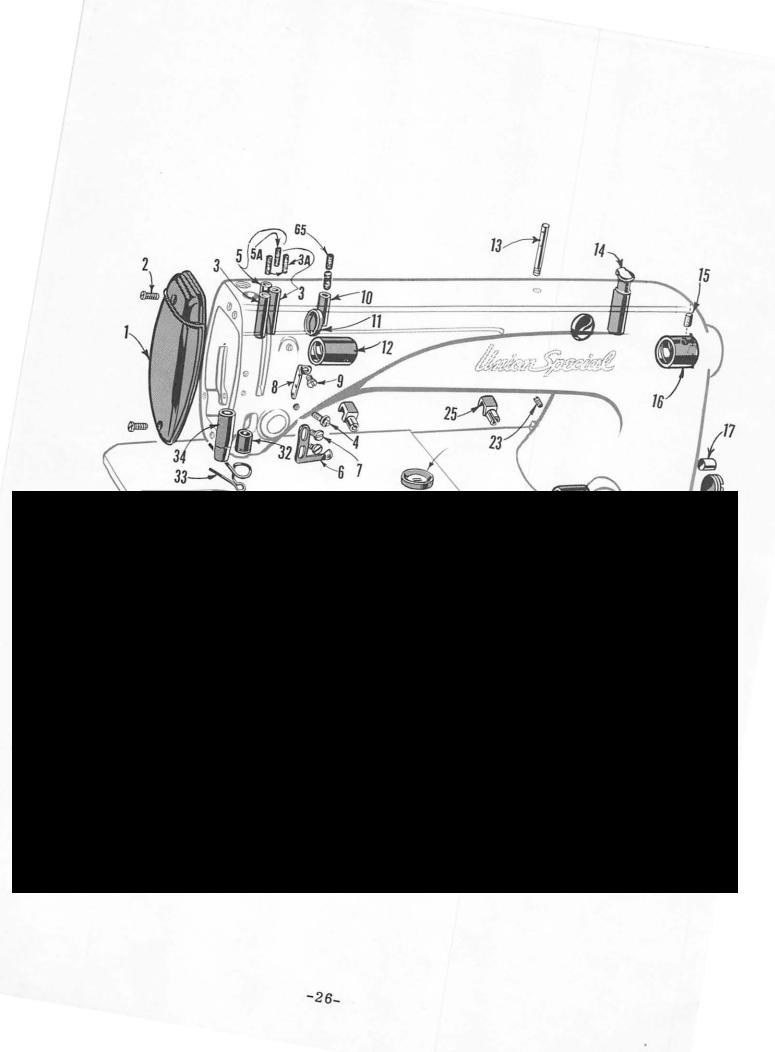
MAIN FRAME, MISCELLANEOUS BUSHINGS, COVERS AND PLATES |
|
||||||||
|
Ref. |
Part |
|
|
|
|
|
|
Amt. |
|||
|
No. |
No. |
|
|
|
|
Description |
Req. |
||||
\ |
|
|
|
|
HeadCover |
|
|
|
|
|
1 |
|
1 |
B61382 |
H |
|
|
|
|
|
|||||
|
2 |
22569 |
B |
Screw----------------------------------------------------------------- |
|
|
|
|
|
|
2 |
|
|
3 |
61293 |
|
Oil Tube -------------------------------------------------------------- |
|
|
|
61293 |
|
_:_____________ |
2 |
|
|
3A |
666-126 |
|
Oil Wick, for No. |
|
2 |
||||||
|
4 |
22863 B |
Tension Assembly Adjusting Screw -------------------------------------- |
|
|
1 |
||||||
|
5 |
61393 c |
Oil Tube, |
for all Styles except 61400 N, P |
-------------------------------- |
1 |
||||||
|
|
61393 E |
Oil Tube, |
for Styles 61400 N, P ----------------------------------------- |
|
|
1 |
|||||
|
sA |
666-127 |
|
Oil Wick, for No. |
61393 C ------------------------------------------ |
|
|
1 |
||||
|
6 |
61351 |
J |
Thread Eyelet--------------------------------------------------------- |
|
|
|
|
|
1 |
||
|
7 |
22585 |
A |
Screw----------------------------------------------------------------- |
|
|
|
|
|
|
2 |
|
|
8 |
61271 |
A |
Thread Eyelet--------------------------------------------------------- |
|
|
|
|
|
1 |
||
|
9 |
22570 |
Screw----------------------------------------------------------------- |
|
|
|
|
|
|
1 |
||
|
10 |
61393 B |
Oil Tube -------------------------------------------------------------- |
|
|
|
|
|
|
1 |
||
|
11 |
61293 |
N |
Plug, for inside of arm------------------------------------------------- |
|
|
2 |
|||||
|
12 |
61490 |
A |
Main Shaft Bushing, |
|
left ------------------------------------------------ |
|
|
1 |
|||
|
13 |
61272 |
AE |
Needle Thread Guide |
Pin------------------------------------------------ |
|
|
1 |
||||
|
14 |
61394 |
Oil Cup--------------------------------------------------------------- |
|
|
|
|
|
|
1 |
||
|
15 |
666-104 |
|
Oil Wick ------------------------------------------------------------- |
|
|
right |
|
|
1 |
||
|
16 |
61490 |
|
|
Main Shaft Bushing, |
|
|
|
1 |
|||
|
17 |
50-558 Blk. |
Plug------------------------------------------------------------------ |
|
|
|
|
|
|
1 |
||
|
18 |
22539 |
D |
Plug Screw------------------------------------------------------------ |
|
|
|
|
|
1 |
||
|
19 |
50-568 Blk. |
Oil Sight Gauge -------------------------------------------------------- |
|
|
|
|
|
1 |
|||
|
20 |
61245 |
G |
Stitch Regulator Thumb Screw Locking Insert ----------------------------- |
1 |
|||||||
|
21 |
22597 |
A |
Screw----------------------------------------------------------------- |
|
|
|
|
|
|
1 |
|
|
22 |
61432 |
B |
Feed Driving Shaft Bushing, right---------------------------------------- |
|
|
1 |
|||||
|
23 |
22597 |
A |
Screw---------------------------------------------- |
|
|
|
|
|
~------------------ |
1 |
|
|
24 |
61449 |
H |
Stitch Regulator Indicator Window---------------------------------------- |
|
|
1 |
|||||
|
25 |
61375 |
|
|
Hinge Stud------------------------------------------------------------- |
|
|
|
|
|
2 |
|
|
26 |
61432 |
D |
Feed Driving Shaft Oil Retaining Bushing, |
right --------------------------- |
1 |
||||||
|
27 |
61432 |
E |
Feed Driving Shaft Oil Retaining Bushing, |
left----------------------------- |
1 |
||||||
|
28 |
61432 |
c |
Feed Driving Shaft Bushing, left----------------------------------------- |
|
|
1 |
|||||
|
29 |
61341 |
D |
Hook Shaft Bushing, |
|
right----------------------------------------------- |
|
|
1 |
|||
|
30 |
61341 |
c |
Hook Shaft Bushing, |
|
left ------------------------------------------- |
|
· ·---- |
1 |
|||
|
31 |
96A |
Screw----------------------------------------------------------------- |
|
|
lower |
|
|
1 |
|||
|
32 |
61454 |
|
|
Needle Bar Bushing, |
|
|
1 |
||||
|
33 |
6147E) |
B |
Needle Thread Guide, |
for Styles 61400 A, B, E, F, G, H, J, AA, BA------------- |
1 |
||||||
|
|
61470 |
·Frame Thread Guide, |
for Styles 61400 N, P, R, S--------------------------- |
1 |
|||||||
|
34 |
61457 |
c |
Presser Bar Bushing, |
lower, for Styles 61400 A, B, E, F, G, H, J, AA, BA------ |
1 |
||||||
|
35 |
376 |
|
Screw----------------------------------------------------------------- |
|
|
|
|
|
|
2 |
|
|
36 |
61402 |
|
|
Bed Slide-------------------------------------------------------------- |
|
|
|
|
|
1 |
|
|
37 |
61273 |
A |
Bed Slide Spring |
--------------------------------------------------- |
|
|
|
1 |
|||
|
38 |
91 |
Screw------------------------------------------------------------- |
|
|
|
|
|
2 |
|||
|
39 |
61414 |
A |
Bobbin Case Holder Positioning Finger----------------------------------- |
|
1 |
||||||
|
40 |
93 |
|
|
Screw----------------------------------------------------------------- |
|
|
|
|
|
|
1 |
|
41 |
22742 |
|
|
Screw----------------------------------------------------------------- |
|
|
|
|
|
|
1 |
|
42 |
22570 |
A |
Throat Plate, See Pages of Throat Plates and Feed Dogs------------------- |
1 |
|||||||
|
43 |
Screw----------------------------------------------------------------- |
|
|
|
|
|
|
4 |
|||
|
44 |
22730 |
|
|
Plug Screw------------------------------------------------------------ |
|
|
|
|
|
1 |
|
|
45 |
660-257 |
|
Gasket---------------------------------------------------------------- |
|
|
|
|
|
|
1 |
|
|
46 |
61282 |
A |
Cover, for hook shaft gear case ----- |
:------------------------------------ |
|
1 |
|||||
|
47 |
61282 |
E |
Gasket---------------------------------------------------------------- |
|
|
|
|
|
|
1 |
|
|
48 |
29475 |
AA |
Tension Assembly, |
for Styles 61400 B, R, S, BA---------------------------- |
1 |
||||||
|
49 |
29475 |
AC |
Tension Assembly, |
for Styles 61400 A, E,-F, G, H, J, N, P, AA ---------------- |
1 |
||||||
|
89 |
A |
Set Screw-------------- |
|
|
.-------------------------------------------- |
|
|
1 |
|||
|
50 |
61492 |
Tension Post Socket------------------------------------------------ |
|
|
1 |
||||||
|
51 |
61492 |
|
|
Tension Post ------------------------------------------------------ |
|
|
|
|
|
1 |
|
|
52 |
61453 |
|
|
Take-up Spring |
---------------------------------------------------- |
|
|
|
|
1 |
|
|
53 |
109 |
H |
Tension Disc ------------------------------------------------------ |
|
|
|
|
|
2 |
||
|
54 |
61292 |
Tension Release Washer-------------------------------------------- |
|
|
1 |
||||||
|
55 |
61392 |
F-9 |
Tension Spring, |
|
for Styles 61400 A, E, F, G, H, J, N, P, AA --------------- |
1 |
|||||
|
|
61392 |
F-14 |
Tension Spring, |
|
for Styles 61400 B, R, S, BA--------------------------- |
1 |
|||||
|
56 |
61292 |
c |
Tension Nut------------------------------------------------------- |
|
|
|
|
|
1 |
||
|
57 |
22597 |
E |
Set Screw |
------------------------------------------------------------- |
|
|
|
|
|
1 |
|
|
58 |
61292 |
G |
Tension Release Pin---------------------------------------------------- |
|
|
|
1 |
||||
|
59 |
22570 |
A |
Screw----------------------------------------------------------------- |
|
|
|
|
|
|
8 |
|
|
60 |
61382 |
J |
Cover, for feed driving shaft gear case----------------------------------- |
|
1 |
||||||
\ |
61 |
61282 |
D |
Gasket---------------------------------------------------------------- |
|
|
|
|
|
|
1 |
|
62 |
61394 |
R |
Gasket------------------------------ |
|
|
|
|
~--------------------------------- |
|
1· |
||
|
63 |
61394 |
Q |
Oil Distributing Plate Retaining Block------------------------------------ |
|
1 |
||||||
|
64 |
61394 |
p |
C>il :Jistributi;·t;:· l?late--------------------------------------------------- |
|
|
1 |
|||||
|
65 |
666-20 |
|
Oil \Vick --- |
~-.; ·· ------------------------------------------------------- |
|
|
|
|
|
2 |
|
-27-
From the library of: Superior Sewing Machine & Supply LLC

 Loading...