


INSTRUCTIONS AND
ILLUSTRATED PARTS LIST
BETRIEBSANLEITUNG UND
ILLUSTRIERTES TEILEVERZEICHNIS
TWO NEEDLE CYLINDER BED DOUBLE LOCKED STITCH
MACHINE FOR ATTACHING CUFF AND HEEL TAPE
ZWEINADEL-ZYLINDER-DOPPELKETTENSTICH-
MASCHINE ZUM ANNÄHEN VON HOSENSTOSSBAND
CATALOG NO. 307
KATALOG NR. 307
SUPPLEMENT TO CATALOG NO. PT9425
ZUSATZ ZUM KATALOG NR. PT9425
SECOND EDITION
ZWEITE AUFLAGE
STYLE / TYP CS112T02-2M111UT
Second edition / Zweite Auflage © Union Special GmbH
09,.2007
2
FOR
KLIPP-IT
MOTOR
METERING
THREAD GUIDES
FÜR
KLIPPAB
MOTOR
BANDZUMESSEINRICHUNG
FADENFÜHRUNG
3

SAFETY RULES
1.Before putting the machines described in this manual intoservice,carefullyreadtheinstructions. Thestarting of each machine is only permitted after taking notice of the instructions and by qualified operators.
IMPORTANT! Before putting the machine into service, also read the safety rules and instructions from the motor supplier.
2.Observethenationalsafetyrulesvalidforyourcountry.
3.The sewing machines described in this instruction manual are prohibited from being put into service until it has been ascertained that the sewing units which these sewing machines will be built into, have conformed with the provisions of EC Machinery Directive 98/37/EC, Annex II B.
Each machine is only allowed to be used as foreseen. The foreseen use of the particular machine is described in paragraph "STYLES OF MACHINES" of this instruction manual. Another use, going beyond the description, is not as foreseen.
4.All safety devices must be in position when the machine is ready for work or in operation. Operation of the machine without the appertaining safety devices is prohibited.
5.Wear safety glasses.
6.In case of machine conversions and changes all valid safety rules must be considered. Conversions and changes are made at your own risk.
SICHERHEITSHINWEISE
1.Lesen Sie vor Inbetriebnahme der in diesem Katalog beschriebenen Maschinen die Betriebsanleitung sorgfältig. Jede Maschine darf erst nach Kenntnisnahme der Betriebsanleitung und nur durch entsprechend unterwiesene Bedienungspersonen betätigt werden.
WICHTIG: Lesen Sie vor Inbetriebnahme auch die Sicherheitshinweise und die Betreibsanleitung des Motorherstellers.
2.Beachten Sie die für Ihr Land geltenden nationalen Unfallverhütungsvorschriften.
3.Die Inbetriebnahme der in dieser Betriebsanleitung beschriebenen Nähmaschinen ist solange untersagt, bis festgestellt wurde daß die Näheinheiten bzw. Nähanlagen, in die diese Nähmaschinen eingebaut werden sollen, den Bestimmungen der EG-Richtlinie Maschinen 98/37/EG, Anhang II B entsprechen.
Jede Maschine darf nur ihrer Bestimmung gemäß verwendet werden. Der bestimmungsgemäße Gebrauch der einzelnen Maschine ist im Abschnitt "MASCHINENTYPEN" der Betriebsanleitung beschrieben. Eine andere, darüber hinausgehende Benutzung ist nicht bestimmungsgemäß.
4.Bei betriebsbereiter oder in Betrieb befindlicher Maschine müssen alle Schutzeinrichtungen montiert sein. Ohne zugehörige Schutzeinrichtungen ist der Betrieb nicht erlaubt.
5.Tragen Sie eine Schutzbrille.
6.UmbautenundVeränderungenderMaschinendürfen nur unter Beachtung der gültigen Sicherheitsvorschriften vorgenommen werden. Umbauten und Veränderungen erfolgen auf eigene Verantwortung.
7.The warning hints in the instructions are marked with one of these two symbols.
8.When doing the following the machine has to be disconnected from the power supply by turning off the main switch or by pulling out the main plug.
8.1When threading needle(s), looper, spreader etc.
8.2When replacing any parts such as needle(s), presser foot, throat plate, looper, spreader, feed dog, needle guard, folder, fabric guide etc.
8.3When leaving the workplace and when the work place is unattended.
8.4When doing maintenance work.
8.5When using clutch motors without actuation lock, wait until motor is stopped totally.
7.Überall da, wo die Betriebsanleitung Warnhinweise enthält, sind diese durch eines der beiden Symbole gekennzeichnet.
8.Bei folgendem ist die Maschine durch Ausschalten am Hauptschalter oder durch Herausziehen des Netzsteckers vom Netz zu trennen:
8.1Zum Einfädeln von Nadel(n), Greifer, Leger usw.
8.2Zum Auswechseln von Nähwerkzeugen, wie Nadel, Drückerfuß, Stichplatte, Greifer, Leger, Transporteur, Nadelanschlag, Apparat, Nähgutführung usw.
8.3Beim Verlassen des Arbeitsplatzes und bei unbeaufsichtigtem Arbeitsplatz.
8.4Für Wartungsarbeiten.
8.5Bei mechanisch betätigten Kupplungsmotoren ohne Betätigungssperre ist der Stillstand des Motors abzuwarten.
4
9.Maintenance, repair and conversion work (see item 8) must be done only by trained technicians or special skilled personnel under condsideration of the instructions.
Only genuine spare parts approved by UNION SPECIAL have to be used for repairs.
10.Any work on the electrical equipment must be done by an electrician or under direction and supervision of special skilled personnel.
11.Work on parts and equipment under electrical power is not permitted. Permissible exceptions aredescribedintheapplicablesectionofstandard sheet EN 50 110 / VDE 0105.
12.Before doing maintenance and repair work on the pneumatic equipment, the machine has to be disconnected from the compressed air supply. In case of existing residual air pressure after disconnecting from compressed air supply (e.g. pneumatic equipment with air tank), the pressure has to be removed by bleeding. Exceptions are onlyallowedforadjustingworkandfunctionchecks done by special skilled personnel.
9.Wartungs-, Reparaturund Umbauarbeiten (siehe Punkt 8) dürfen nur von Fachkräften oder entsprechend unterwiesenen Personen unter Beachtung der Betriebsanleitung durchgeführt werden.
Für Reparaturen sind nur die von UNION SPECIAL freigegebenen Original-Ersatzteile zu verwenden.
10.Arbeiten an der elekrischen Ausrüstung dürfen nur von Elektrofachkräften oder unter Leitung und Aufsicht von entsprechend unterwiesenen Personen durchgeführt werden.
11.Arbeiten an unter Spannung stehenden Teilen und Einrichtungensindnichterlaubt.Ausnahmenregeln die zutreffenden Teile der EN 50 110 / VDE 0105.
12.Vor Wartungsund Reparaturarbeiten an pneumatischen Einrichtungen ist die Maschine vom pneumatischen Versorgungsnetz zu trennen. Wenn nach der Trennung vom pneumatischen Versorgungsnetz noch Restenergie ansteht (z. B. bei pneumatischen Einrichtungen mit Windkessel), ist diese durch Entlüften abzubauen. Ausnahmen sindnurbeiEinstellarbeitenundFunktionsprüfungen durch entsprechend unterwiesene Fachkräfte zulässig.
5
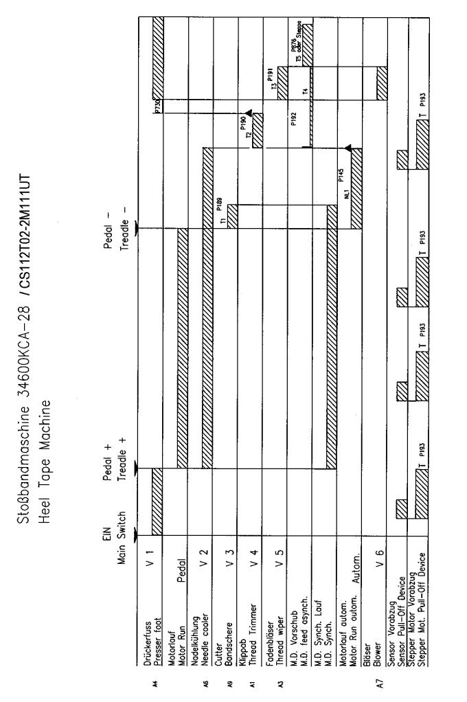
Instructions for Heel Tape Machine with Quick Motor 997A736
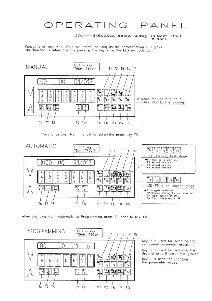
As shown on page “Operating Panel” the following LED’s have to be lit in the MANUAL – MODE (press the appertaining key to switch LED “ON” or “OFF”).
T11 – means |
Needle up at machine stop |
T13 – means |
Presser foot up at end of seam |
T14 – means |
KLIPP-IT works in “Manual-Mode” |
F5 off or flashing: |
1rst level for F1 to F4 keys active |
|
F1 flashing, metering device running. |
F5 on |
2nd level for F1 to F4 keys active. |
|
F1 flashing, thread blower active behind KLIPP-IT. |
LED’s of keys T6, T7, T8, T12 and T15 are included in all modes MANUAL,AUTOMATIC and PROGRAMMING “OFF”.
Within this mode you can handle the sewing-in of the machine, while the metering device is not running.
AUTOMATIC MODE
Apart from all LED’S flashing as in the MANUAL MODE, now switch on T9 to achieve AUTOMATIC-MODE “ON”.
When actuating the foot pedal forward while in this mode the metering device runs synchronously with the sewing machine. Moving the foot pedal back activates cutting of the tape, end – beginning automatically sewn with chainstitch, threads cut, presser foot up, the needle threads are blown over the presser foot and the tape is inserted.
PROGRAMMING MODE
A-Level
Apart from all LED’s flashing as in the MANUAL MODE, now switch on T10 to achieve PROGRAMMING MODE, level A “ON”.
Important parameters in the A-level:
P145 |
|
excess seam length |
P872 |
|
speed, insert tape |
P875 |
|
transmission ratio Metering Devise to main motor |
P876 |
|
length, insert tape |
P959 |
(RO) |
gathering factor 1 |
P951 |
(R1) |
gathering factor 2 |
P952 |
(R2) |
gathering factor 3 |
P953 |
(R3) |
gathering factor 4 |
P954 |
(R4) |
gathering factor 5 |
B-Level
Master switch “OFF”
Press keys T9 and T10 simultaneously and turn master switch “ON”.
In T9 LED has to be “OFF”, if not press key T9. In T10 LED has to be “ON”, otherwise press key T10. Use key P to select the hundred group.
Use key S to select the tens and the units. Use key L to change parameter value.
The most important parameters have been listed on a separate sheet titled “parameter”.
6

As the gathering factors of tapes or trouser cloths are likely to vary, we can select 5 different gathering factors. To adjust transmission ratio of the metering device to the main motor we recommend to proceed as follows:
Set parameter 875 to 15 Set parameter 950 to 0
Now sew tape desired onto the respective trouser cloth. If the heel tape is too short use key “L” in programming mode (level B) to select a lower value of P875. Factor in parameter P875 has been selected correctly, if the tape has been attached smooth and evenly without any loops between presser foot and metering device.
Now you are ready to insert the factors in parameters 951, 952 and 954. The higher the factor the shorter the heel tape length.
Press key “P” to select a gathering factor R0 to R4 in the AUTOMATIC MODE.
7
Anleitung für Stoßband mit Quick-Motor 997A736
G:\—KCA \ Anleitung für Stoßband
Wie im Blatt „Bedienfeld“ gezeigt, müssen folgende LED`s im MANUELL - Modus brennen (drükken auf die entsprechende Taste schaltet die LED „AN“ oder „AUS“):
T11 Bedeutung: |
Nadel oben wenn Maschine anhält |
|
T13 Bedeutung: |
Drückerfuß oben wenn Nähoperation beendet. |
|
T14 Bedeutung: |
Klippab arbeitet im Manuell - Modus. |
|
F5 aus oder blinkt: |
1. Ebene für die F1 bis F4 Taste ist aktiv. |
|
|
|
F1 brennt, Metering arbeitet. |
F5 an |
: |
2. Ebene für die F1 bis F4 Taste ist aktiv. |
|
|
F1 brennt, Fadenbläser ist nach dem Klippab aktiv. |
Die LEDs der Tasten T6, T7, T8, T12 und T15 sind in den Modi Manuell, Automatik und Programmieren „AUS“.
In diesem Modus kann die Maschine eingenäht werden, das Metering arbeitet nicht.
Automatik – Modus:
Alle LED‘s wie im Manuell – Modus, jedoch T9 nun einschalten, dadurch Automatik – Modus EIN.
In diesem Modus arbeitet das Metering beim Vorwärtstreten des Pedals synchron mit der Nähmaschine. Wird das Pedal nach hinten getreten wird das Band geschnitten, Ende - Anfang automatisch übernäht, die Fäden geschnitten, der Drückerfuß geht hoch, die Nadelfäden werden über den Drückerfuß geblasen und das Band vorgelegt.
Programmier – Modus:
A-Ebene
Alle LED‘s wie im Manuell – Modus, jedoch T10 nun einschalten, dadurch Programmier – Modus, Ebene A, EIN.
Wichtige Parameter in der A-Ebene: P145 Übernählänge
P872 Geschwindigkeit, Band einschießen
P875 Übersetzung Metering zu Hauptmotor
P876 Länge, Band einschießen
P950 (R0) Raffwert 1
P951 (R1) Raffwert 2
P952 (R2) Raffwert 3
P953 (R3) Raffwert 4
P954 (R4) Raffwert 5
B-Ebene
Hauptschalter „AUS“
Taste T9 und T10 gleichzeitig drücken und Hauptschalter „EIN“.
In T9 muss die LED AUS sein, ist dies nicht der Fall, Taste T9 drücken. In T10 muss die LED AN sein, eventuell Taste T10 drücken.
Mit der P-Taste wird die Hundertergruppe ausgewählt.
Mit der S-Taste wird die Zehnerund Einerstelle angewählt. Mit der L-Taste wird der Wert des Parameter geändert.
Die wichtigsten Parameter sind auf dem Blatt „Parameter“ aufgeführt.
8
Die wichtigsten Parameter sind auf dem Blatt „Parameter“ aufgeführt.
Da der Raffwert je nach Band oder Hosenstoff unterschiedlich ist kann man 5 verschiedene Raffwerte wählen.
Die Übersetzung vom Metering zum Hauptmotor wird wie folgt eingestellt: Parameter 875 auf 15 stellen.
Parameter 950 auf 0 stellen.
Nun wird das gewünschte Stoßband auf den entsprechenden Hosenstoff genäht. Ist das Band zu kurz muss der Wert von P875 im Programmier Modus (B Ebene) mit der Taste „ L “niedriger gewählt werden.
Wird das Band glatt aufgenäht und zwischen Drückerfuß und Metering bildet sich keine Schlaufe ist der Wert in P875 richtig gewählt.
Jetzt können die Werte in Parameter 951, 952, 953 und 954 eingegeben werden. Je höher der Wert desto kürzer wird das Stoßband.
Durch drücken der „P“ Taste kann der Raffwert von R0 bis R4 im AUTOMATIK MODUS ausgewählt werden.
9
10
11

12
13
11.4List of Parameters (2A_401_2.EN2)
No. Function(Meaning) |
Level |
Range of |
Standard |
||
|
|
|
|
Values |
Value |
105 |
(AR/DRZ/STVD) Speed for front |
B,C |
100 - 6400 |
3500 |
|
|
backtack/stitch condensation |
|
|
|
|
|
(00000011) |
|
|
|
|
106 |
(AR/DRZ/STVD) Speed for front |
B,C |
|
0 |
|
|
backtack/stitch condensation |
|
|
|
|
|
I variable (treadle-controlled) |
|
|
|
|
|
II constant (corresponding to <105>) |
|
|
|
|
107 |
(AR/RIE/DRZ/STVD) Speed for front |
B,C |
|
0 |
|
|
backtack/stitch condensation when <106> = I |
|
|
|
|
|
I |
limited by <105> |
|
|
|
|
II |
limited by <607> |
|
|
|
110 |
(ER/RIE/DRZ/STVD) Speed for end |
B,C |
100 - 6400 |
5000 |
|
|
backtack/stitch condensation |
|
|
|
|
111 |
(LS) Photocell compensation stitches 1 |
A,B,C |
1 - 255 |
6 |
|
|
(stitches from photocell clear to seam end) |
|
|
|
|
112 |
(LS) Number of stitches for photocell fade-out |
A,B,C |
0 - 255 |
0 |
|
|
on knit fabrics (according to stitch size) |
|
|
|
|
113 |
(LS/START) Start with photocell |
B,C |
|
0 |
|
|
I when photocell is dark only |
|
|
|
|
|
II also when photocell is clear |
|
|
|
|
114 |
(PR/STOP/NE) Stop before seam end after |
B,C |
|
0 |
|
|
stitch count (last seam section) |
|
|
|
|
|
I |
yes |
|
|
|
|
II |
no |
|
|
|
116 |
(SANL) Soft start stitches |
A,B,C |
0 - 255 |
0 |
|
|
(00000111) |
|
|
|
|
117 |
(SANL/DRZ) Speed for soft start stitches |
B,C |
30 - 640 |
400 |
|
133 |
(PR) Stitches for seam section 6 |
A,B,C |
1 - 255 |
2 |
|
134 |
(PR) Stitches for seam section 7 |
A,B,C |
0 - 2550 |
300 |
|
141 |
(FW) Number of stitches until bobbin thread |
B,C |
0 - 255 |
10 |
|
|
monitor signal becomes active |
|
|
|
|
|
(signal suppression on bobbin thread monitor) |
|
|
|
|
145 |
(NE) Number of stitches for seam end |
A,B,C |
0 - 255 |
15 |
|
|
(00001001) |
|
|
|
|
161 |
(LS/START) Start delay for start of photocell |
B,C |
0 - 2550 |
70 |
|
189 |
(VERZ) Delay t1 |
B,C |
0 - 2550 |
50 |
|
190 |
(VERZ) Delay t2 |
B,C |
0 - 2550 |
180 |
|
191 |
(VERZ) Delay t3 |
B,C |
0 - 2550 |
600 |
|
192 |
(VERZ) Delay t4 |
B,C |
0 - 2550 |
1000 |
|
199 |
(DRZ/LS) Speed for photocell compensation |
B,C |
300 - 6400 |
2000 |
|
|
stitches |
|
|
|
|
206 |
(NE/PR/STOP) Interrupt/discontinue seam |
B,C |
|
0 |
|
|
sections at speed = constant (<203> = II) |
|
|
|
|
|
I |
with treadle -2 |
|
|
|
|
II |
with treadle 0 |
|
|
|
14
11.4Parameterliste (2A_401_2.DE2)
Nr. |
Funktion(Bedeutung) |
Ebene Einstell- |
Standard- |
||
|
|
|
|
bereich |
wert |
105 |
(AR/DRZ/STVD) Drehzahl für Anfangsriegel/ |
B,C |
100 - 6400 |
3500 |
|
|
-stichverdichtung |
|
|
|
|
|
(00000011) |
|
|
|
|
106 |
(AR/DRZ/STVD) Drehzahl für Anfangsriegel/ |
B,C |
|
0 |
|
|
-stichverdichtung |
|
|
|
|
|
I |
variabel (pedalabhängig) |
|
|
|
|
II |
konstant (entspr. <105>) |
|
|
|
107 |
(AR/DRZ/STVD) Drehzahl für Anfangsriegel/ |
B,C |
|
0 |
|
|
-stichverdichtung bei <106> = I |
|
|
|
|
|
I |
begrenzt durch <105> |
|
|
|
|
II |
begrenzt durch <607> |
|
|
|
110 |
(ER/RIE/DRZ/STVD) Drehzahl für Endriegel/ |
B,C |
100 - 6400 |
5000 |
|
|
-stichverdichtung |
|
|
|
|
111 |
(LS) Lichtschrankenausgleichsstiche 1 |
A,B,C |
1 - 255 |
6 |
|
|
(Stichzahl von Lichtschranke hell bis |
|
|
|
|
|
Nahtende) |
|
|
|
|
112 |
(LS) Stichzahl zur Lichtschrankenausblendung A,B,C |
0 - 255 |
0 |
||
|
bei Maschenware(entsprechend der |
|
|
|
|
|
Maschenweite) |
|
|
|
|
113 |
(LS/START) Start mit Lichtschranke |
B,C |
|
0 |
|
|
I nur wenn Lichtschranke dunkel |
|
|
|
|
|
II auch wenn Lichtschranke hell |
|
|
|
|
114 |
(PR/STOP/NE) Stopp vor Nahtende nach |
B,C |
|
0 |
|
|
Stich zählung (letzte Nahtstrecke) |
|
|
|
|
|
I |
ja |
|
|
|
|
II |
nein |
|
|
|
116 |
(SANL) Sanftanlaufstiche (Soft start) |
A,B,C |
0 - 255 |
0 |
|
|
(00000111) |
|
|
|
|
117 |
(SANL/DRZ) Drehzahl für Sanftanlaufstiche |
B,C |
30 - 640 |
400 |
|
133 |
(PR) Stiche für Nahtstrecke 6 |
A,B,C |
1 - 255 |
2 |
|
134 |
(PR) Stiche für Nahtstrecke 7 |
A,B,C |
0 - 2550 |
300 |
|
141 |
(FW) Stichzahl bis Spulenfadenwächter-SignalB,C |
0 - 255 |
10 |
||
|
wirksam ist |
|
|
|
|
|
(Signalunterdrückung des Spulenfadenwächters) |
|
|
||
145 |
(NE) Stichzahl für Nahtende |
A,B,C |
0 - 255 |
15 |
|
|
(00001001) |
|
|
|
|
161 |
(LS/START) Startverzögerung für |
B,C |
0 - 2550 |
70 |
|
|
Lichtschrankenstart |
|
|
|
|
189 |
(VERZ) Verzögerungszeit t1 |
B,C |
0 - 2550 |
50 |
|
190 |
(VERZ) Verzögerungszeit t2 |
B,C |
0 - 2550 |
180 |
|
191 |
(VERZ) Verzögerungszeit t3 |
B,C |
0 - 2550 |
600 |
|
192 |
(VERZ) Verzögerungszeit t4 |
B,C |
0 - 2550 |
1000 |
|
199 |
(DRZ/LS) Drehzahl für |
B,C |
300 - 6400 |
2000 |
|
|
Lichtschrankenausgleichs stiche |
|
|
|
|
206 |
(NE/PR/STOP) Unterbrechen/Abbrechen |
B,C |
|
0 |
|
|
der Nahtstrecken bei Drehzahl = konstant (<203> = II) |
|
|
||
|
I |
mit Pedal -2 |
|
|
|
|
II |
mit Pedal 0 |
|
|
|
15
221 |
(PR/DB/DRZ) Speed limitation for sewing |
B,C |
300 - 6400 |
1200 |
|
|
programs (or sewing program 1) |
|
|
|
|
419 |
(RIV/RIUNT/STVD) Function of external key |
B,C |
|
0 |
|
|
I |
backtack/stitch condensation inversion |
|
|
|
|
II |
backtack/stitch condensation suppression |
|
|
|
|
(flip-flop function) |
|
|
|
|
425 |
(ENTKET) Unlocking of chain at seam end |
A,B,C |
|
0 |
|
|
I |
yes |
|
|
|
|
II |
no |
|
|
|
427 |
(PF/HV/PULL/STOP/MESSER) Selection of |
B,C |
1 - 5 |
5 |
|
|
the function available with input E4 |
|
|
|
|
|
1 = presser foot |
|
|
|
|
|
2 = stroke adjustment |
|
|
|
|
|
3 = control of puller@4 = stop |
|
|
|
|
|
5 = chopper |
|
|
|
|
|
6-9 without function |
|
|
|
|
568 |
(TUM/STVD/BSN) output A4 is at |
B,C |
|
0 |
|
|
I Feed reverse / stitch condensation |
|
|
|
|
|
II Tape cutter |
|
|
|
|
601 |
(SN) Trimming |
B,C |
|
0 |
|
|
I |
yes |
|
|
|
|
II |
no |
|
|
|
602 |
(NE) Seam end at treadle position |
B,C |
|
0 |
|
|
I |
slightly heeled (-1) |
|
|
|
|
II fully heeled (-2) |
|
|
|
|
603 |
(START) Start after seam end |
B,C |
|
0 |
|
|
I after treadle 0 only |
|
|
|
|
|
II immediate start of operation |
|
|
|
|
605 |
(DRZ) Actual speed in display |
B,C |
|
0 |
|
|
I |
yes |
|
|
|
|
II |
no |
|
|
|
606 |
(DRZ) Speed: level 1 (min.) |
B,C |
30 - 640 |
200 |
|
|
(00010001) |
|
|
|
|
607 |
(DRZ) Speed: level 12 (max.) |
B,C |
100 - 10000 |
4000 |
|
608 |
(DRZ) Speed level curve (treadle |
B,C |
|
0 |
|
|
characteristic) |
|
|
|
|
|
I |
linear |
|
|
|
|
II |
not linear |
|
|
|
609 |
(SN/DRZ) Trimming speed 1 |
B,C |
30 - 300 |
200 |
|
|
(00010011) |
|
|
|
|
613 |
(ANLSP/STOP) Input „Ex“ induces block/stop |
B,C |
|
0 |
|
|
at |
|
|
|
|
|
I |
potential „zero“ |
|
|
|
|
II |
potential „plus“ |
|
|
|
615 |
(LS) End recognition when photocell goes |
B,C |
|
0 |
|
|
I from light to dark |
|
|
|
|
|
II from dark to light |
|
|
|
|
616 |
(NPW/NHOS) Function of external key (input |
B,C |
|
0 |
|
|
E2) |
|
|
|
|
I needle position change-over (NPW)
II needle up without trimming (NHOS)
16
221 |
(PR/DB/DRZ) Drehzahlbegrenzung für Näh- |
B,C |
300 - 6400 |
1200 |
|
|
programme (bzw. Nähprogramm 1) |
|
|
|
|
419 |
(RIV/RIUNT/STVD) Funktion des externen |
B,C |
|
0 |
|
|
Tasters |
|
|
|
|
|
I |
Riegelinvertierung/ Stichverdichtungsinvertierung |
|
|
|
|
II |
Riegelunterdrückung/Stichverdichtungs- |
|
|
|
|
unterdrückung (Flip-Flop-Funktion) |
|
|
|
|
425 |
(ENTKET) Entketteln am Nahtende |
A,B,C |
|
0 |
|
|
I |
ja |
|
|
|
|
II |
nein |
|
|
|
427 |
(PF/HV/PULL/STOP/MESSER) Auswahl der |
B,C |
1 - 5 |
5 |
|
|
Funktion des Eingangs E4 |
|
|
|
|
|
1 = |
Presserfuß |
|
|
|
|
2 = |
Hubverstellung |
|
|
|
|
3 = |
Pullersteuerung 4 = Stopp |
|
|
|
|
5 = |
Abhacker |
|
|
|
|
6 - 9 z. Z. keine Funktion |
|
|
|
|
568 |
(TUM/STVD/BSN) Ausgang A5 ist bei |
|
B,C |
0 |
|
|
I |
Transportumstellung / Stichverdichtung |
|
|
|
|
II |
Bandschneider |
|
|
|
601 |
(SN) Schneiden |
|
B,C |
0 |
|
|
I |
ja |
|
|
|
|
II |
nein |
|
|
|
602 |
(NE) Nahtende bei Pedalstellung |
B,C |
|
0 |
|
|
I |
leicht rückwärts (-1) |
|
|
|
|
II |
voll rückwärts (-2) |
|
|
|
603 |
(START) Start nach Nahtende |
B,C |
|
0 |
|
|
I nur nach Pedal 0 |
|
|
|
|
|
II |
sofortiger Nähbeginn |
|
|
|
605 |
(DRZ) Istwert in der Anzeige(<725>) |
B,C |
|
0 |
|
|
I |
ja |
|
|
|
|
II |
nein |
|
|
|
606 |
(DRZ) Drehzahl: Stufe 1 (min.) |
B,C |
30 - 640 |
200 |
|
|
(00010001) |
|
|
|
|
607 |
(DRZ) Drehzahl: Stufe 12 (max.) |
B,C |
100 - 10000 |
4000 |
|
608 |
(DRZ) Drehzahlstufenkurve |
B,C |
|
0 |
|
|
(Pedalcharakteristik) |
|
|
|
|
|
I |
linear |
|
|
|
|
II |
nicht linear |
|
|
|
609 |
(SN/DRZ) Schneiddrehzahl 1 |
B,C |
30 - 300 |
200 |
|
|
(00010011) |
|
|
|
|
613 |
(ANLSP/STOP) Eingang“Ex“ führt zu |
B,C |
|
0 |
|
|
Laufsperre/Stopp |
|
|
|
|
|
I |
bei Potential „null“ |
|
|
|
|
II |
bei Potential „plus“ |
|
|
|
615 |
(LS) Enderkennung durch Lichtschranke |
B,C |
|
0 |
|
|
I von hell nach dunkel |
|
|
|
|
|
II von dunkel nach hell |
|
|
|
|
616 |
(NPW/NHOS) Funktion des externen Tasters |
B,C |
|
0 |
|
|
(Eingang E2) |
|
|
|
|
|
I |
Nadelpositionswechsel (NPW) |
|
|
|
II Nadel hoch ohne Schneiden (NHOS)
17
617 |
(EST/RIV/STVD) Function of external key |
B,C |
|
0 |
|
|
(input E3) |
|
|
|
|
|
I |
single stitch (EST) |
|
|
|
|
II backtack/stitch condensation inverted (RI |
|
|
|
|
|
V) |
|
|
|
|
618 |
(RDR) Inverse rotation after seam end |
B,C |
|
0 |
|
|
I |
yes |
|
|
|
|
II |
no |
|
|
|
619 |
(SN/ANLSP/STOP) Control of thread trimming B,C |
|
0 |
||
|
(safety switch no run) |
|
|
|
|
|
I |
yes |
|
|
|
|
II |
no |
|
|
|
620 |
(FW) Thread monitor function |
B,C |
|
0 |
|
|
I |
yes |
|
|
|
|
II |
no |
|
|
|
623 |
(RDR/VERZ) Delay in start-up time (ms) for |
B,C |
0 - 2550 |
10 |
|
|
inverse rotation |
|
|
|
|
633 |
(SN/PF) Trimming and presser foot |
B,C |
|
0 |
|
|
I with treadle „-2“ only (<602> = II) |
|
|
|
|
|
II |
corresponding to <602> |
|
|
|
640 |
(LS/START) Start possible by obscuring the |
B,C |
|
0 |
|
|
photocell (if existing, note parameter 113!) |
|
|
|
|
|
I |
yes |
|
|
|
|
II |
no |
|
|
|
641 |
(LS/START/VERZ) Delay before start (ms) |
B,C |
0 - 2550 |
150 |
|
|
after photocell (at <640> = I) |
|
|
|
|
651 |
(PF) Presser foot with automatic descent on |
B,C |
|
0 |
|
|
machine stop |
|
|
|
|
|
I |
yes |
|
|
|
|
II |
no |
|
|
|
653 |
(PEIPO) Target stitch before sewing |
B,C |
|
0 |
|
|
I |
yes |
|
|
|
|
II |
no |
|
|
|
668 |
(BLA/WI) Thread wiper/thread clearer |
B,C |
|
0 |
|
|
I |
yes |
|
|
|
|
II |
no |
|
|
|
|
(00010101) |
|
|
|
|
675 |
(NAPO) Automatic needle change-over into |
B,C |
|
0 |
|
|
position@2 (up) after enabling |
|
|
|
|
|
I |
yes |
|
|
|
|
II |
no |
|
|
|
676 |
(DRZ) Speed adjustment via potentiometer |
B,C |
|
0 |
|
|
possible |
|
|
|
|
|
I |
yes |
|
|
|
|
II |
no |
|
|
|
700 |
(NAPO) Needle position 0 |
B,C |
0 - 239 |
0 |
|
|
(reference position of the needle) |
|
|
|
|
701 |
(NAPO) Angular adjustment |
B,C |
|
0 |
|
|
I with handwheel (teach-in) |
|
|
|
|
|
II by keys (+/-) |
|
|
|
|
18
 Loading...