


63400A

From the library of: Superior Sewing Machine & Supply LLC
®
FINEST
QU
A
LITY
STY
LE
S
634
00
A
634
00B
CATALOG
No.
121
M
SECOND
EDITION
CLASS
63400
S
TRE
A
MLINED
INDUSTRIAL
SEWING
MACH
INES
HI
GH S
PEED
L
OCKS
TIT
CH
MA
C
HINE
S
UNION SPECIAL
CORPORATION
CHICAGO
From the library of: Superior Sewing Machine & Supply LLC
Catalog
No.
121
M
INSTRUCTIONS
FOR
ADJUSTING
AND
OPERATING
LIST
OF
PARTS
CLASS
63400
Streamlined
Lockstitch
Styles
63400
A
63400
B
Second
Edition
®
1961
By
Union
Special
Corporation
Rights
Reserved
in
All
Countries
UNION SPECIAL CORPORATION
INDUSTRIAL
SEWING
MACHINES
CHICAGO
Printed
in
U.S.A.
2
August,
1981
From the library of: Superior Sewing Machine & Supply LLC
IDENTIFICATION
OF
MACHINES
Each
UNION
SPECIAL
machine
is
identified
by a
Style
number which
is
stamped
into
the
name
plate
on
the
machine.
Style
numbers
are
classified
as
standard
and
special.
Standard
Style
numbers
have one
or
more
letters
suffixed,
but
never
contain
the
letter
"Z".
Example:
"Style
63400
A".
Special
Style
numbers
contain
the
letter
"Z".
When
only
minor changes
are
made
in
a
standard
machine,
a "Z"
is
suffixed
to
the
Standard
Style
number.Example:
"Style
63400 AZ".
Styles
of
machines
similar
in
construction
are
grouped
under
a
class
number which
differs
from
the
style
number,
in
that
it
contains
no
letters.
Example:
"Class
63400".
APPLICATION
OF
CATALOG
This
catalog
applies
specifically
to
the
Standard
Styles
of
machines
as
listed
herein.
It
can
also
be
applied
with
discretion
to
some
Special
Styles
of
machines
in
this
Class.
Refer-
ence
to
direction,
such
as
right,
left,
front,
back,
etc.,
are
given
from
the
operator's
posi-
tion
while
seated
at
the
machine.
Operating
direction
of
the
handwheel
is
toward
the
operator.
STYLES
OF
MACHINES
High
Speed
Streamlined
Long
Arm
Lockstitch
Machines,
One
Needle,
Light,
Medium
and Heavy
Duty,
Drop
Feed,
Rotary
Hook,
Horizontal
Hook
Shaft,
Push
Button
Stitch
Regulator,
Stitch
Length
In-
dicator,
One
Reservoir
Enclosed
Automatic
Lubricating
System, Head
Oil
Siphon,
Adjustable
Hook
Oil
Control,
Automatic
Head
Oiling,
Needle
Bearing
Adjustable
Feed
Eccentric,
Needle
Bearings
for
Take-up
Lever
and
Needle
Bar
Driving
Link,
Feed Timing on Lower Main
Shaft,
Maximum
Work
Space
to
Right
of
Needle
Bar 11
1/8
Inches.
*63400 A
For
miscellaneous
plain
seaming
operations
on
light
and medium
weight
work, 1
9/64
inch
needle
bar
travel.
Type 183
GXS
or
183
GYS
needle.
Specify
presser
foot,
throat
plate,
feed
dog,
stitches
per
inch,
thread
size,
needle
type
and
size,
attachments
and
guides.
63400 B
For
miscellaneous
plain
seaming
operations
on medium and medium heavy
weight
work,
1
13/64
inch
needle
bar
travel.
Type 180
GXS
or
180
GYS
needle.
Specify
presser
foot,
throat
plate,
feed
dog,
stitches
per
inch,
thread
size,
needle
type
and
size,
attachment
and
guides.
*
DISCONTINUED
-
In
most
instances,
component
parts
can
be
ordered
for
customer
repair.
NEEDLES
Each
needle
has
both
a
type
and
size
number. The
type
number
denotes
the
kind
of
shank,
point,
length,
groove,
finish
and
other
details.
The
size
number, stamped on
the
needle
shank,
denotes
largest
diameter
of
the
blade
measured
across
the
eye.
Collectively,
the
type
number
and
the
size
number
represent
the
complete
symbol.
Needle
Type 180
GXS
or
180
GYS
is
reconnnended
for
Style
63400
Band
needle
Type 183
GXS
or
183
GYS
is
recommended
for
Style
63400
A.
Their
description
and
the
sizes
available
are
listed
below.
Type No.
180
GXS
180
GYS
183
GXS
183
GYS
Description
and
Sizes
Round
shank,
round
point,
lockstitch,
short
length,
ball
eye,
single
groove,
wide
angle
groove,
struck
groove,
deep
spot,
ball
point,
chromium
plated
-
sizes
075/029,
080/032,
090/036,
100/040,
110/044, 125/049,
140/054,
150/060.
Round
shank,
round
point,
lockstitch,
short
length,
ball
eye,
single
groove,
wide
angle
groove,
struck
groove,
deep
spot,
chromium
plated
-
sizes
075/029,
080/032,
090/036,
100/040, 110/044,
125/049,
140/054,
150/060.
Round
shank,
round
point,
lockstitch,
extra
short
length,
ball
eye,
single
groove,
wide
angle
groove,
struck
groove,
deep
spot,
ball
point,
chromium
plat
ed -
sizes
025,
075/029,
080/032, 090/036,
100/040,
110/044.
Round
shank,
round
point,
lockstitch,
extra
short
length,
ball
eye,
si
n
gle
groove,
wide
angle
groove,
struck
groove,
deep
spot,
chromium
plated
-
sizes
028,
080/032,
090/036,
040,
044.
3
From the library of: Superior Sewing Machine & Supply LLC
NEEDLES
(Continued)
To
have
needle
orders
promptly
and
accurately
filled,
an
empty
package,
a
sample
needle,
or
the
type
and
size
number
should
be
forwarded.
Use
description
on
label.
A
complete
order
would
read:
11
1000
Needles,
Type
180
GXS,
Size
080
/ 032'~
Selection
of
proper
needle
size
should
be
determined
by
the
size
of
the
thread
used.
Thread
should
pass
freely
through
the
needle
eye
in
order
to
produce
a
good
stitch
formation.
SELECTING
THE
SIZE
OF
THE
NEEDLE
The
strength
requirement
of
the
seam
produced
·.
is
largely
dependent
upon
the
size
of
the
thread
employed.
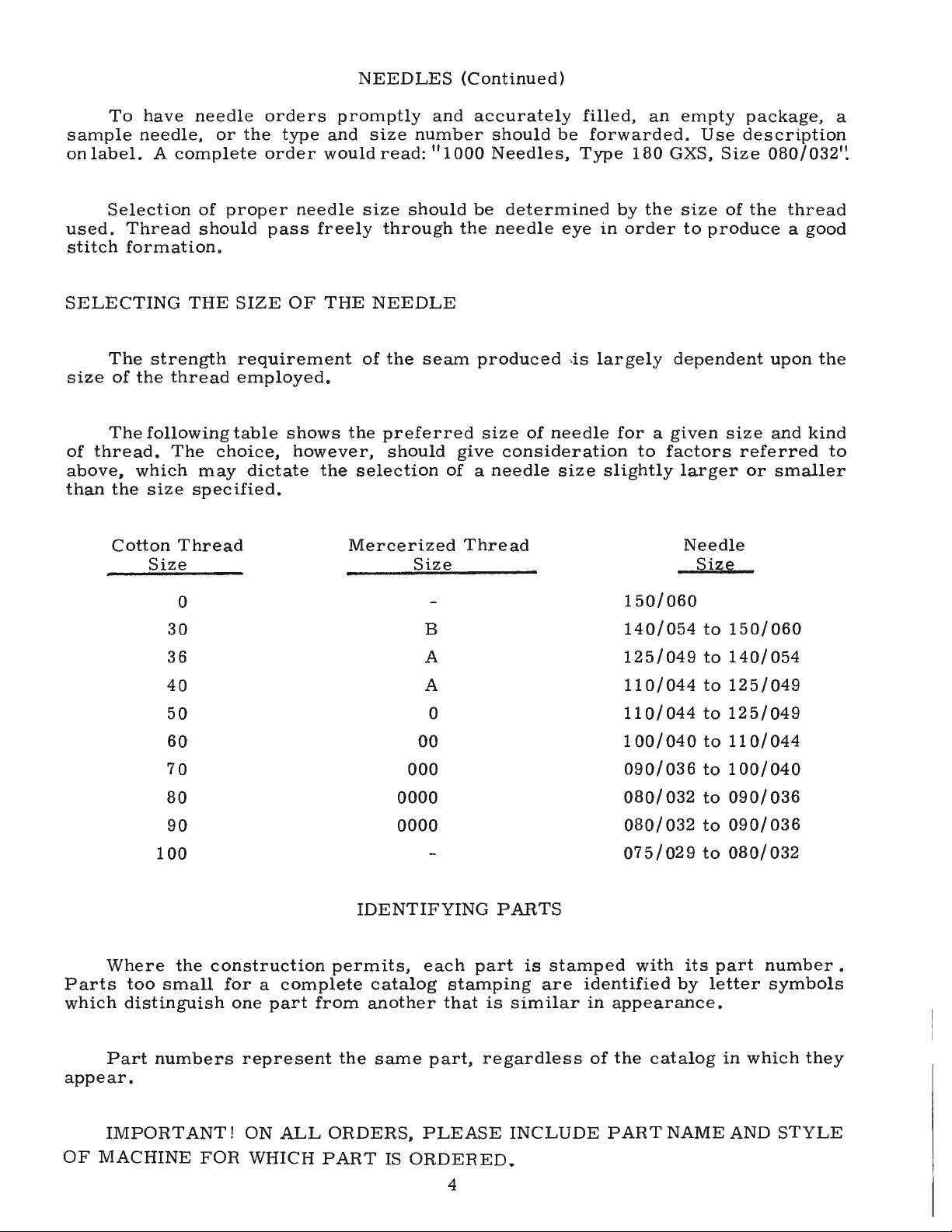
The
following
table
shows
the
preferred
size
of
needle
for
a
given
size
and
kind
of
thread.
The
choice,
however,
should
give
consideration
to
factors
referred
to
above,
which
may
dictate
the
selection
of
a
needle
size
slightly
larger
or
smaller
than
the
size
specified.
Cotton
Thread
Size
0
30
36
40
50
60
70
80
90
100
Mercerized
Thread
Size
B
A
A
0
00
000
0000
0000
IDENTIFYING
PARTS
Needle
Size
150/060
140/054
to
150/060
125/049
to
140/054
110/044
to
125/049
110/044
to
125/049
100/
040
to
110/
044
090/036
to
100/040
080/
032
to
090/
036
080/
032
to
090/
036
075/029
to
080/032
Where
the
construction
permits,
each
part
is
stamped
with
its
part
number.
Parts
too
small
for
a
complete
catalog
stamping
are
identified
by
letter
symbols
which
distinguish
one
part
from
another
that
is
similar
in
appearance.
Part
numbers
represent
the
same
part,
regardless
of
the
catalog
in
which
they
appear.
IMPORTANT!
ON
ALL
ORDERS,
PLEASE
INCLUDE
PART
NAME
AND
STYLE
OF
MACHINE
FOR
WHICH
PART
IS
ORDERED.
4
From the library of: Superior Sewing Machine & Supply LLC
ORDERING
OF
REPAIR
PARTS
ILLUSTRATIONS
The
arrangement
of
this
catalog
is
to
facilitate
easy
and
accurate
ordering
of
Class
63400
replacement
parts.
Six
exploded
view
plattes
cover
the
Standard
Styles
listed
in
this
catalog.
Each
plate
presents
a
sector
of
the
machine,
parts
being
aligned
as
in
their
assembled
po-
sition.
Small
keyline
views
show
by
a
blackended
area
exactly
where
the
parts
being
discussed
fit
in
the
assembled
machine.
On
the
page
opposite
the
illustration
will
be
found
a
listing
of
the
parts
with
their
part
numbers,
descriptions
and
the
number
of
pieces
required
in
the
particular
view
being
shown.
Numbers
in
the
first
column
are
reference
numbers
only,
and
merely
indicate
the
position
of
the
part
in
the
illustration.
Reference
numbers
should
never
be
used
in
ordering
parts.
Always
use
the
part
number
listed
in
the
second
column. Each
exploded
view
plate
carries
a
reference
number
for
each
part
for
sale.
Sub-assemblies,
which
are
sold
complete,
or
by
separate
part,
are
in
a
bracket
or
a
solid
line
box
on
the
picture
plate.
Component
parts
of
sub-assemblies,
which
can
be
furnished
for
repairs,
are
indicated
by
indenting
their
descriptions
under
the
description
of
the
main
sub-assembly.
Example:
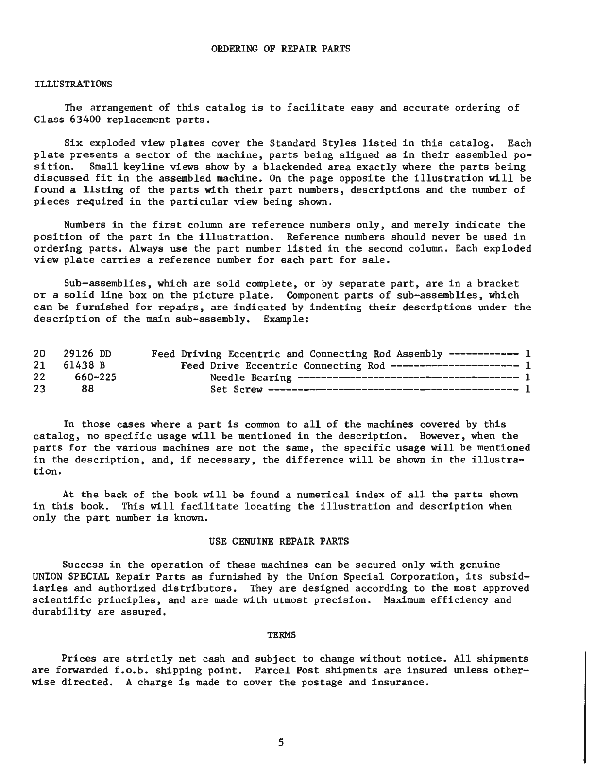
20
21
22
23
29126
DD
61438
B
660-225
88
Feed
Driving
Eccentric
and
Connecting
Rod
Assembly------------
1
Feed
Drive
Eccentric
Connecting
Rod----------------------
1
Needle
Bearing--------------------------------------
1
Set
Screw-------------------------------------------
1
In
those
cases
where
a
part
is
connnon
to
all
of
the
machines
covered
by
this
catalog,
no
specific
usage
will
be
mentioned
in
the
description.
However, when
the
parts
for
the
various
machines
are
not
the
same,
the
specific
usage
will
be
mentioned
in
the
description,
and,
if
necessary,
the
difference
will
be
shown
in
the
illustra-
tion.
At
the
back
of
the
book
will
be
found
a
numerical
index
of
all
the
parts
shown
in
this
book.
This
will
facilitate
locating
the
illustration
and
description
when
only
the
part
number
is
known.
USE
GENUINE
REPAIR
PARTS
Success
in
the
operation
of
these
machines
can
be
secured
only
with
genuine
UNION
SPECIAL
Repair
Parts
as
furnished
by
the
Union
Special
Corporation,
its
subsid-
iaries
and
authorized
distributors.
They
are
designed
according
to
the
most
approved
scientific
principles,
and
are
made
with
utmost
precision.
Maximum
efficiency
and
durability
are
assured.
TERMS
Pric
es
are
strictly
net
cash
and
subject
to
change
without
notice.
All
shipments
are
forwarded
f.o.b.
shipping
point.
Parcel
Post
shipments
are
insured
unless
other-
wise
directed.
A
charge
is
made
to
cover
the
postage
and
insurance.
5

From the library of: Superior Sewing Machine & Supply LLC
INSTALLING
CAUTION!
When
unpacking,
DO
NOT
lift
machine
out
of
box
by
placing
one
hand
on
handwheel.
Using
both
hands
on
bed
casting,
lift
gently.
Before
leaving
factory,
each
UNION
SPECIAL
machine
is
sewed
off,
inspected
and
carefully
packed.
After
the
machine
and
accessories
have
been
removed
from
the
packing
box,
the
following
steps
should
be
followed:
PHEPAHATION
OF
MACHINE
FOH
INSTALLATION
A
bag
of
assembly
parts,
consisting
of
one
frame
thread
eyelet,
one
eyelet
attaching
screw,
one
extra
bobbin,
two
hinge
studs,
and
two
screws
for
holding
miscellaneous
attachments
to
the
bed
plate,
is
packed
with
each
machine.
Insert
hinge
studs
in
holes
provided
for
them
in
rear
of
cloth
plate.
Assemble
the
upper
frame
eyelet
(A,
Fig.
2).
STANDARD
ACCESSORIES
Included
also
with
each
machine
is
a
box
of
STANDARD
ACCESSORIES--containing
one
bobbin
winder
assembly,
the
machine
mounting
frame,
one
oil
drain
jar
and
its
clamp
spring,
one
knee
lifter
assembly
and
its
rubber
pad,
bed
positioning
spring
and
screw,
four
isolator
pads
and
clips,
and
one
machine
rest
pin,
These
parts
are
essential
when
setting
up
the
machine.
TABLE
TOPS
Lockstitch
machines
are
installed
in
table
tops,
prepared
with
cut-out,
so
that
the
bed
plate
is
FLUSH
with
the
top
of
the
machine
mounting
frame.
MACHINE
MOUNTING
FRAME
INSTALLATION
On
a
suitable
tableboard,
place
machine
mountin
g
frame
(21393
N)
in
the
machine
cut-out
with
the
hinge
lugs
to
the
rear
(Fig.
1 ).
Insert
the
countersunk
wood
screw
throu
gh
left
hinge
pad
and
tighten
securely.
Assemble
bed
posit10ning
spring
(63474
A)
over
right
hinge
pad;
insert
round
head
wood
screw
and
tighten
securely.
Assemble
the
retaining
plate
(21393
R)
to
outside
front
of
pan
section,
as
shown,
and
snu
g
up
nuts
lightly.
Place
sewing
head
in
the
frame
mountin
g,
and
after
bein
g
sure
there
is
about
1
/16
inch
clearance
between
the
cloth
plate
edge
and
the
frame
sides,
rap
the
retaining
plate
smartly
upward
with
a
hammer
to
insure
a
good
grip
on
the
underside
of
the
board
and
tighten
Jockin
g
nuts
securely.
Tip
machine
back
against
rest
pin,
and
assemble
the
knee
press
assembly
as
shown.
All
end
play
of
the
cross
shaft
should
be
taken
up
by
the
cone
bearin
g
s,
but
must
not
bind,
61477
;:
166
3 0
2l393N_/
~
-
63476C
Fig.
1
6
60-168
6

From the library of: Superior Sewing Machine & Supply LLC
INSTALLING
(Continued)
MACHINE
MOUNTING
FRAME
INSTALLATION
(Continued)
Before
the
machine
is
put
into
production,
the
bell
crank
(21665
J)
of
the
knee
lifter
rod
should
be
adjusted.
The
left
stop
screw
(22597
F)
should
be
set
so
that
the
maximum
lift
of
the
presser
bar
and
its
parts
do
not
interfere
with
moving
parts
within
the
head.
This
may
be
done
by
setting
the
stop
screw
so
that
the
presser
bar
raises
approximately
5/16
inch.
BOBBIN
WINDER
The
bobbin
winder
should
be
secured
to
the
table
top
so
that
its
pulley
will
be
located
directly
in
front
of
the
sewing
machine
belt
and
will
bear
against
the
belt
when
in
operation.
The
base
of
the
winder
has
two
elongated
attaching
holes,
which
allow
the
mechanism
to
be
moved
closer
to
or
farther
away
from
belt
as
needed.
The
pulley
of
the
winder,
when
in
operation,
should
exert
only
enough
pressure
against
the
belt
to
wind
the
bobbin.
Regulation
and
operation
of
the
bobbin
winder
is
described
under
"Winding
the
Bobbin",
under
OPERATOR'S
INSTRUCTIONS.
BELTS
These
machines
are
equipped
to
use
either
#1
"Vee"
or
round
belts.
Fig.
2
7

From the library of: Superior Sewing Machine & Supply LLC
LUBRICATION
CAUTION!
Oil
has
been
drained
from
the
main
reservoir
before
shipment
and
the
reservoir
must
be
filled
before
starting
to
operate.
Lubricate
machine
thoroughly,
in
accordance
with
instructions
which
follow,
and
run
slowly
for
several
minutes
to
distribute
the
oil
to
the
various
parts.
Full
speed
operation
can
then
be
expected
without
damage.
RECOMMENDED
OIL
Us9
a
stainless
water-white
straight
mineral
oil
ofaSaybolt
viscosity
of
90
to
125
seconds
at
100
Fahrenheit
in
the
main
reservoir.
This
is
equivalent
to
Union
Special
specification
No.
175.
Fill
main
reservoir
at
plug
screw
(B,
Fig.
2}
and
check
oil
level
at
gauge
(C};
oil
is
at
maximum
level
when
needle
is
in
yellow
band
marked
"full".
Oil
should
be
added
when
needle
is
in
yellow
band
marked
II
low".
It
is
recommended
that
a
new
machine,
or
onethathas
been
out
of
service
for
an
extended
period,
be
lubricated
as
follows:
Remove
the
end
cover
and
directly
oil
the
bearings
of
the
needle
bar
link,
take-up
and
its
lever
and
needle
bar.
Replace
end
cover
as
no
further
hand
oiling
will
be
required.
CAUTION!
The
machine
is
provided
with
automatic
or
manual
head
mechanism
oil
control.
The
oil
control
dial
(D,
Fig.
2}
is
shown
in
the
automatic
oiling
position,
and
should
manual
Siling
of
the
head
mechanism
be
desired,
remove
locking
screw
(G,
Fig.
2}
and
turn
dial
180
to
expose
the
manual
oiling
port.
In
the
manual
oiling
position,
five
or
six
drops
of
oil
should
be
introduced
into
the
oiling
port
twice
daily
-
preferably
at
starting
time
and
mid-day.
Oil
may
be
drained
from
main
reservoir
by
removing
plug
screw
(F,
Fig.
2).
OIL GAUGE
The
oil
gauge
is
set
at
the
factory
to
show
the
proper
oil
level
in
the
reservoir.
Should
an
adjustment
become
necessary,
the
following
steps
should
be
followed:
1.
Place
the
machine
upright
on
a
level
table
or
bench.
2.
Remove
the
reservoir
plug
screw
(located
below
the
handwheel
and
near
the
bottom
of
the
machine}.
3.
Oil
should
be
added
or
removed
so
that
the
oil
level
is
approximately
1/
8
inch
below
the
bottom
edge
of
the
hole.
4.
Loosen
the
lock
nut
on
the
calibrating
screw,
and
turn
the
screw
left
or
right
so
that
the
gauge
needle
rests
on
the
yellow
band
marked
"FULL"
on
gauge
(C,
Fig.
2).
5.
Tighten
lock
nut
and
replace
plug
screw.
Fig.
3
Lubrication
ofthe
mechanism
below
the
cloth
plate
is
automatically
accomplished
through
the
feed
driving
shaft
(D,
Fig.
3},
which
is
tubular.
Oil
is
introduced
into
the
shaft
at
the
sprocket
end
by
means
of
an
oil
distributing
plate
(A,
Fig.
3}
which
is
secured
to
the
bottom
cover
(B)
by
means
of
two
screws
(C}.
Should
it
become
necessary
to
remove
the
reservoir
cover,
it
is
imperative
that
the
adjustment
of
the
oil
distributing
plate
(A)
be
checked
very
carefully.
This
can
be
done
by
removing
the
large
plug
screw
at
the
right
end
ofthe
reservoir
andlooking
through
the
hole.
The
low
point
of
the
oil
distributing
plate
must
be
even
with
or
slightly
below
the
center
of
shaft
(D}
and
just
touching
it.
8
From the library of: Superior Sewing Machine & Supply LLC
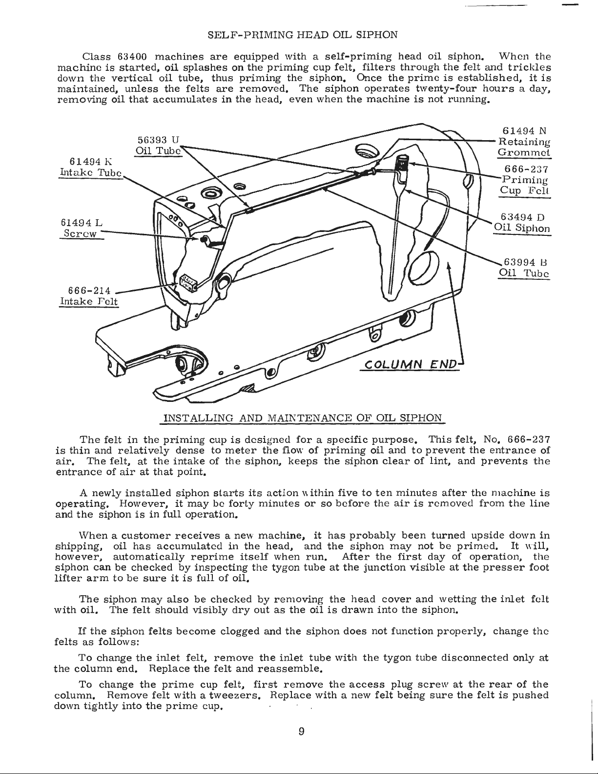
SELF-PRIMING
HEAD
OIL
SIPHON
Class
63400
machines
are
equipped
with
a
self-priming
head
oil
siphon.
When
the
machine
is
started,
oil
splashes
on
the
priming
cup
felt,
filters
through
the
felt
and
trickles
down
the
vertical
oil
tube,
thus
priming
the
siphon.
Once
the
prime
is
established,
it
is
maintained,
unless
the
felts
are
removed.
The
siphon
operates
twenty-four
hours
a
day,
removing
oil
that
accumulates
in
the
head,
even
when
the
machine
is
not
running.
61494
K
Intake
Tube
61494
L
Screw-----!.
61494
N
r----~~---
Retaining
INSTALLING
AND
MAINTENANCE
OF
OIL
SIPHON
Grommet
666-237
Priming
Cup
F'cll.
63494
D
Oil
Siphon
63994
13
Oil
Tube
The
felt
in
the
priming
cup
is
desi
g
ned
for
a
specific
purpose.
This
felt,
No.
666-237
is
thin
and
relatively
dense
to
meter
the
flow
of
priming
oil
and
to
prevent
the
entrance
of
air.
The
felt,
at
the
intake
of
the
siphon,
keeps
the
siphon
clear
of
lint,
and
prevents
the
entrance
of
air
at
that
point.
A
newly
installed
siphon
starts
its
act
i
on
within
five
to
ten
minutes
after
the
machine
is
operating.
However,
it
may
be
forty
minutes
or
so
before
the
air
is
removed
from
the
line
and
the
siphon
is
in
full
operation.
When
a
customer
receives
a
new
machine,
it
has
probably
been
turned
upside
down
in
shipping,
oil
has
accumulated
in
the
head,
and
the
siphon
may
not
be
primed.
It
will,
however,
automatically
reprime
itself
when
run.
After
the
first
day
of
operation,
the
siphon
can
be
checked
by
inspecting
the
ty
g
on
tube
at
the
junction
visible
at
the
presser
foot
lifter
arm
to
be
sure
it
is
full
of
oil.
The
siphon
may
also
be
checked
by
removin
g
the
head
cover
and
wetting
the
inlet
felt
with
oil.
The
felt
should
visibly
dry
out
as
the
oil
is
drawn
into
the
siphon.
If
the
siphon
felts
become
clogged
and
the
siphon
does
not
function
properly,
change
the
felts
as
follows:
To
change
the
inlet
felt,
remove
the
inlet
tube
with
the
tygon
tube
disconnected
only
at
the
column
end.
Replace
the
felt
and
reassemble.
To
change
the
prime
cup
felt,
first
remove
the
access
plug
screw
at
the
rear
of
the
column.
Remove
felt
with
a
tweezers.
Replace
with
a
new
felt
being
sure
the
felt
is
pushed
down
tightly
into
the
prime
cup.
9

From the library of: Superior Sewing Machine & Supply LLC
INSTRUCTIONS
FOR
OPERATORS
THREAD
While
the
direction
of
the
twist
in
the
bobbin
thread
1s
immaterial,
the
direction
of
the
hook
rotation
favors
the
use
of
a
left
twist
thread
in
the
needle.
To
determine
the
direction
of
twist,
grasp
a
short
length
of
thread
between
thumb
and
forefinger
of
each
hand.
Turn
the
thread
away
from
you
with
your
right
hand.
If
the
strands
unwind,
it
is a
left
twist,
if
not,
it
is
a
right
twist.
REMOVING
THE
BOBBIN
CASE
To
remove
the
bobbin
case,
turn
handwheel
in
operating
direction
until
the
needle
reaches
its
highest
position.
Using
the
left
hand,
reach
under
the
table,
open
the
bobbin
case
latch
(A,
Fig.
4),
and
pull
the
bobbin
case
out
of
the
sewing
hook.
Fig.
4
WINDING
THE
BOBBIN
Opening
the
latch
retains
the
bobbin
in
the
case.
When
the
latch
is
closed,
the
bobbin
is
released
and
can
readily
be
removed.
Thread
the
bobbin
winder
by
leading
the
thread
from
the
supply
down
through
the
eyelet
(A,
Fig.
5),
down
between
the
tension
discs,
and
under
the
tension
post.
Press
an
empty
bobbin
on
the
winder
shaft
(B)
up
to
the
stop,
wind
the
end
of
thread
around
the
bobbin
a
few
turns
in
a
clockwise
direction,
and
press
down-
wardly
on
hand
lever
(D)
until
pulley
is
moved
into
contact
with
machine
belt,
and
is
locked
in
that
position.
When
the
machine
is
operated,
the
bobbin
will
be
rotated
and
filled
until
the
thread
engages
the
automatic
throw-out
member,
which
disengages
the
pulley.
The
extent
to
which
the
bobbin
is
filled
can
be
varied
by
regulating
the
screw
(C).
The
tension
post
bracket
is
mounted
on
the
winder
base,
and
can
be
shifted
fromleftto
right
by
loosening
screw
(E)
so
that
any
tendency
of
the
bobbin
to
wind
unevenly
may
be
readily
corrected.
The
purpose
of
the
bobbin
winder
is
to
assure
an
Fig.
5
operator
of
a
full
bobbin
at
all
times.
When
the
bobbin
in
the
machine
is
used
up,
replace
it
with
the
full
one,
and
begin
to
wind
the
empty
one
immediately.
Bobbins
can
be
rewound
while
the
machine
is
sewing.
Fig.
6
THREADING
THE
BOBBIN
CASE
The
bobbin
case
should
beheld
between
the
thumb,
forefinger
and
second
finger
of
the
LEFT
hand
(A,
Fig.
6).
The
bobbin
itself
should
be
held
between
the
thumb
and
forefinger
of
the
right
hand
(B,
Fig.
6)
with
thread
coming
off
the
bottom
of
the
bobbin.
10

From the library of: Superior Sewing Machine & Supply LLC
INSTRUCTIONS
FOR
OPERA
TORS
(Continued)
THREADING
THE
BOBBIN
CASE
(
Continued)
Place
the
bobbin
in
the
bobbin
case.
In
one
continuous
motion,
with
the
thumb
and
forefinger
of
the
right
hand,
draw
the
bobbin
thread
through
the
diagonal
slot
in
bobbin
case
(A,
Fig.
7)
under
the
tension
spring
(B)
and
into
self
threading
eyelet
(C)
on
case.
Note
the
direction
of
the
rotation
of
the
bobbin
as
the
end
of
the
thread
is
pulled
when
looking
at
the
bobbin
case
from
the
back.
The
bobbin
should
rotate
\
counterclockwise.
RE
PLACING
THE
BOBBIN
CASE
Have
the
needle
bar
at
its
highest
position,
allow
about
two
and
one
half
inches
of
thread
to
hang
free.
The
bobbin
case
latch
should
be
opened
with
the
left
hand,
and
by
reaching
under
the
table
and
through
the
opening
in
the
table,
it
should
be
placed
C
part
way
into
the
sewing
hook.
The
latch
should
then
be
released
and
bobbin
case
snapped
into
position.
INSERTING
THE
NEEDLE
Fig.
7
Insert
the
needle
into
the
needle
bar
as
far
as
it
will
go
with
the
spot
(
sometimes
called
scarf)
toward
the
right,
facing
the
handwheel.
Tighten
set
screw
securely.
A
The
cross
hole
in
the
needle
bar,
about
1/
4
inch
from
the
end
(A,
Fig.
8),
is
to
show
the
operator
when
the
needle
has
been
inserted
as
far
up
as
it
will
go,
and
to
provide
a
means
for
cleaning
the
accumulated
lint
from
needle
hole
so
the
needle
will
seat
properly.
THREADING
THE
NEEDLE
Threading
diagram
(Fig.
2)
shows
the
places
where
the
needle
Fig.
8
thread
passes.
Please
note
that
the
needle
thread
passes
through
the
needle
eye
from
left
to
right.
PREPARATION
FOR
SEWING
With
your
left
hand,
hold
the
end
of
the
needle
thread,
leaving
it
slack,
and
turn
the
handwheel
in
operating
direction
until
the
needle
moves
down
and
up
again
to
its
highest
position.
Pull
up
the
needle
thread
and
the
bobbin
thread
will
come
up
with
it
through
the
needle
hole
in
the
throat
plate.
Draw
both
threads
under
the
presser
foot.
B
TENSIONS
A
perfect
stitch
is
one
in
which
the
needle
thread
and
bobbin
thread
are
locked
together
in
the
center
of
the
material
being
sewed.
A
stitch
of
this
kind
is
secured
by
regulating
the
tensions
on
both
threads.
BOBBIN
THREAD
TENSION
The
tension
on
the
bobbin
case
is
applied
by
means
of
a
set
Fig.
9
screw
(A,
Fig.
9)
which
regulates
tension
spring
(B).
The
tension
on
the
spring
is
correct
when
it
is
just
sufficient
to
hold
the
bobbin
case
and
bobbin
suspended
by
the
bobbin
thread.
The
thread
should
not
be
in
the
eyelet
for
this
adjustment
check.
11

From the library of: Superior Sewing Machine & Supply LLC
INSTRUCTIONS
FOR
OPERA
TORS
(Continued)
BOBBIN
THREAD
TENSION
(Continued)
Remove
the
bobbin
case
from
its
holder
and
turn
set
screw
in
spring
in
a
clockwise
direction
to
apply
more
tension
or
counterclockwise
to
release
tension.
When
the
bobbin
thread
tension
is
correct,
it
rarely
becomes
necessary
to
make
any
changes
as
varying
the
needle
thread
tension
will
usually
attain
a
good
stitch.
NEEDLE
THREAD
TENSION
The
needle
thread
tension
is
varied
by
turning
the
tension
regulating
nut
(H,
Fig.
2).
Turning
the
nut
in
a
clockwise
direction
increases
the
tension,
while
counterclockwise
decreases
it.
This
should
not
be
done
when
the
presser
foot
is
in
its
raised
position,
but
is
generally
done
while
the
machine
is
sewing
on
a
piece
of
scrap
material.
TO
CHANGE
THE
STITCH
LENGTH
Press
plunger
(J,
Fig.
2)
in
firmly.
While
holding
plunger
in,
turn
handwheel
in
operating
direction
until
stitch
regulating
finger
is
felt
to
drop
into
the
slot
of
feed
eccentric.
Continuing
to
hold
the
plunger
in,
turn
handwheel
in
operating
direction
to
increase
the
stitch
length
and
in
opposite
direction
to
decrease
the
stitch
length.
Stitch
lengths
are
indicated
by
graduations
on
the
indicator
dial
and
are
viewed
through
the
window
in
the
belt
guard
(K,
Fig.
2).
PRESSURE
ON
MA
TE
RIAL
The
presser
spring
should
exert
only
enough
pressure
to
make
the
work
feed
uniformly.
To
increase
the
pressure
on
the
presser
foot,
turn
presser
spring
regulator
(A,
Fig.
10)
in
clockwise
direction.
Turning
the
regulator
counterclockwise
decreases
the
pressure.
12
Fig.
10

From the library of: Superior Sewing Machine & Supply LLC
INSTRUCTIONS
FOR
MECHANICS
SETTING
THE
NEEDLE
BAR
TO
HEIGHT
The
lower
needle
bar
bushing,
the
one
to
which
the
needle
bar
is
timed,
is
set
at
the
factory.
The
distance
from
the
bottom
of
bushing
(A,
Fig.
11)
to
the
throat
plate
seat
is
2
1/
4
inches.
Fig.
11
The
four
lines
engraved
on
the
needle
bar
are
used
in
setting
needle
bar
to
height
and
are
referred
to
as
TIMING
LINES.
The
two
upper
lines
are
used
with
the
extra
short
length
needle
Type
183
GXS
or
183 GYS,
which
are
recommended
for
Style
63400
A.
The
two
lower
lines
are
used
with
the
short
length
needle
Type
180 GXS
or
180 GYS,
which
are
recommended
for
Style
63400
B.
When
the
needle
bar
is
at
its
lowest
position,
the
upper
timing
line
(B,
Fig.
11)
(of
the
pair
selected)
dependent
upon
the
needle
used,
should
be
EVEN
with
the
lower
edge
of
the
lower
needle
bar
bushing
(A).
To
change
the
position
of
the
needle
bar,
turn
the
handwheel
until
the
bar
is
at
its
lowest
position.
Then,
loosen
the
clamp
screw
(C)
and
move
the
bar
to
the
proper
timing
line.
Keeping
the
needle
bar
link
at
its
lowest
position,
tighten
screw
securely.
The
illustration
(Fig.
11)
shows
the
proper
setting
of
the
needle
bar
on
Style
63400
A,
using
extra
short
length
needle.
Type
183 GXS
or
183 GYS.
The
setting
of
the
needle
bar
on
Style
63400
B,
using
short
length
needle,
Type
180 GXS
or
180
GYS,
is
accomplished
in
the
same
manner,
except
that
the
lower
pair
of
timing
marks
on
the
bar
is
used.
TIMING
THE
HOOK
Tip
the
machine
back
so
that
it
rests
on
the
rest
pin
in
the
table
top.
Insert
a new
needle.
Loosen
the
two
screws
and
swing
out
the
bobbin
case
positioning
finger
(A,
Fig.
12).
Loosen
the
three
set
screws
(B)
in
the
hook
and
hold
the
hook
and
bobbin
case
holder
in
such
a
position
as
to
prevent
interference
with
the
needle.
Turn
the
handwheel
in
operating
direction
until
the
needle
bar
is
at
its
lowest
position
and
continue
to
turn
the
handwheel
until
the
needle
is
ascending
and
the
low
er
timing
mark
(
of
the
pair
selected)
(Fig.
11)
used
in
setting
the
needle
bar
is
even
with
the
lower
edge
of
the
needle
bar
bushing
(A).
Fig.
12
Turn
the
hook
on
the
shaft
until
the
point
of
the
hook
is
even
with
the
center
of
the
needle
and
as
close
to
the
needle
as
possible
without
deflecting
it.
A
spacing
of
. 003
to
•
005
inch
between
the
needle
and
the
point
of
the
hook
is
satisfactory.
With
the
hook
in
this
position,
tighten
the
set
screw
opposite
the
hook
point
securely.
Then,
tighten
the
two
remaining
screws
securely
and
recheck
the
timing
of
the
hook
with
the
needle,
at
which
time,
the
top
of
the
eye
of
the
needle
should
be
about
1/64
inch
below
the
bottom
of
the
hook
point.
If
this
condition
does
not
exist,
recheck
the
setting
of
the
needle
bar
bushing
in
relation
to
the
throat
plate
seat
(Fig.
11).
Adjust
the
bobbin
case
holder
positioning
finger
by
turning
the
bobbin
case
holder
until
the
finger
recess
is
at
the
top.
Place
the
projection
on
the
finger
into
the
bobbin
case
holder
recess
and
tighten
the
finger
attaching
screws
securely,
allowing
1/32
inch
clearance
between
the
outside
edge
of
projection
and
the
inside
edge
of
bobbin
case
recess
(Fig.
12).
13
From the library of: Superior Sewing Machine & Supply LLC
INSTRUCTIONS
FOR
MECHANICS
(Continued)
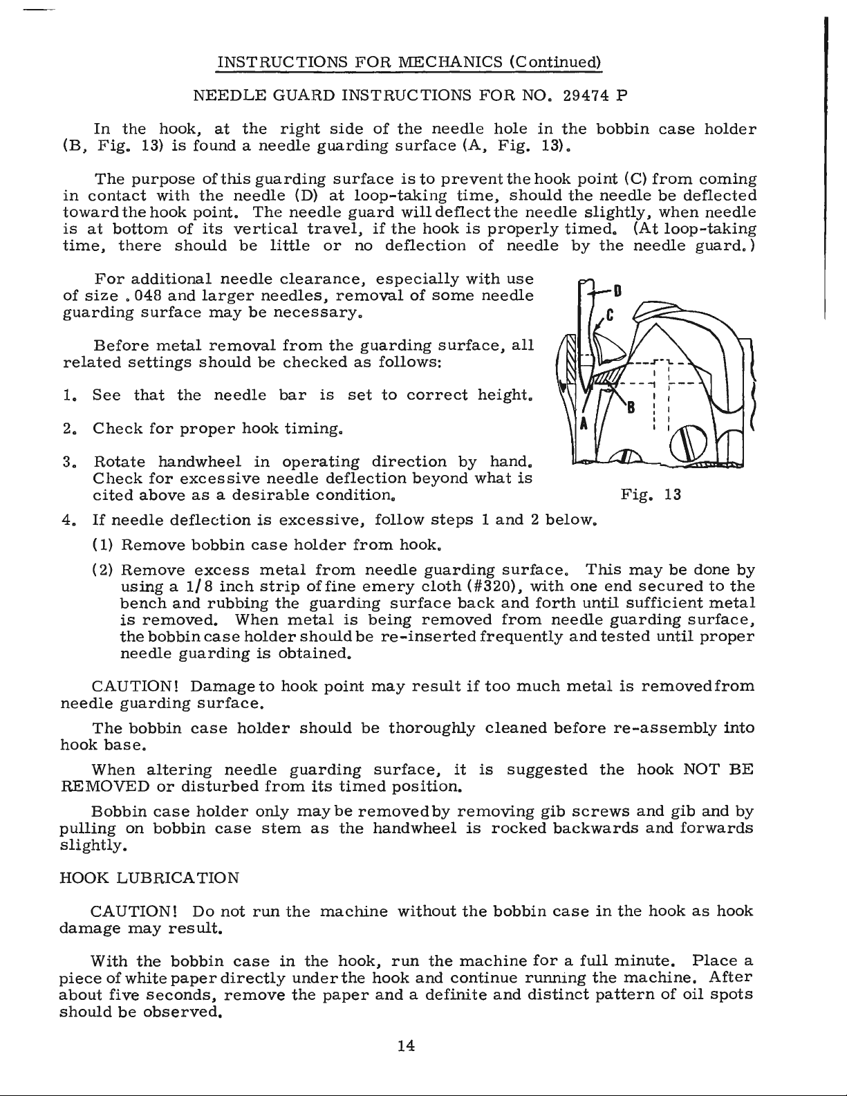
NEEDLE
GUARD
INSTRUCTIONS
FOR
NO.
29474
P
In
the
hook,
at
the
right
side
of
the
needle
hole
in
the
bobbin
case
holder
(B,
Fig.
13)
is
found
a
needle
guarding
surface
(A,
Fig.
13).
The
purpose
of
this
guarding
surface
is
to
prevent
the
hook
point
(C)
from
coming
in
contact
with
the
needle
(D)
at
loop-taking
time,
should
the
needle
be
deflected
toward
the
hook
point.
The
needle
guard
will
deflect
the
needle
slightly,
when
needle
is
at
bottom
of
its
vertical
travel,
if
the
hook
is
properly
timed.
(At
loop-taking
time,
there
should
be
little
or
no
deflection
of
needle
by
the
needle
guard.)
For
additional
needle
clearance,
especially
with
use
of
size
.
048
and
larger
needles,
removal
of
some
needle
guarding
surface
may
be
necessary.
Before
metal
removal
from
the
guarding
surface,
all
related
settings
should
be
checked
as
follows:
1.
See
that
the
needle
bar
is
set
to
correct
height.
2.
Check
for
proper
hook
timing.
3.
Rotate
handwheel
in
operating
direction
by
hand.
Check
for
excessive
needle
deflection
beyond
what
is
cited
above
as
a
desirable
condition.
Fig.
13
4.
If
needle
deflection
is
excessive,
follow
steps
1
and
2
below.
(1)
Remove
bobbin
case
holder
from
hook.
(
2)
Remove
excess
metal
from
needle
guarding
surface.
This
may
be
done
by
using
a
1/8
inch
strip
of
fine
emery
cloth
(#320),
with
one
end
secured
to
the
bench
and
rubbing
the
guarding
surface
back
and
forth
until
sufficient
metal
is
removed.
When
metal
is
being
removed
from
needle
guarding
surface,
the
bobbin
case
holder
should
be
re-inserted
frequently
and
tested
until
proper
needle
guarding
is
obtained.
CAUTION!
Damage
to
hook
point
may
result
if
too
much
metal
is
removed
from
needle
guarding
surface.
The
bobbin
case
holder
should
be
thoroughly
cleaned
before
re-assembly
into
hook
base.
When
altering
needle
guarding
surface,
it
is
suggested
the
hook
NOT
BE
REMOVED
or
disturbed
from
its
timed
position.
Bobbin
case
holder
only
may
be
removed
by
removing
gib
screws
and
gib
and
by
pulling
on
bobbin
case
stem
as
the
handwheel
is
rocked
backwards
and
forwards
slightly.
HOOK
LUBRICATION
CAUTION!
Do
not
run
the
machine
without
the
bobbin
case
in
the
hook
as
hook
damage
may
res
ult.
With
the
bobbin
case
in
the
hook,
run
the
machine
for
a
full
minute.
Place
a
piece
of
white
paper
directly
under
the
hook
and
continue
running
the
machine.
After
about
five
seconds,
remove
the
paper
and
a
definite
and
distinct
pattern
of
oil
spots
should
be
observed.
14

From the library of: Superior Sewing Machine & Supply LLC
INSTRUCTIONS
FOR
MECHANICS
(Continued)
HOOK
LUBRICATION
(Continued)
Should
more
or
less
oil
be
required,
turn
the
oil
control
adjust-
ing
shaft
(E,
Fig.
2),
located
on
the
front
cf
the
machine
just
below
the
cloth
plate
surface,
in
the
direction
of
the
change
required.
After
a
change
in
the
hook
oil
flow,
the
machine
should
be
run
about
one
minute
before
checking
for
the
desired
oil
flow.
FEED
DOG
HEIGHT
In
regulating
the
height
of
the
feed
clog,
it
should
be
at
its
highest
position
and
the
presser
foot
resting
directly
against
it.
The
feed
dog
holder
attaching
Fig.
14
screw
(A,
Fig.
14)
should
be
loosened
slightly,
and
regulating
screw
(B)
should
be
turned
either
clockwise,
to
raise
the
feed
dog,
or
counterclockwise
to
lower
it.
Make
sure
that
the
bottom
of
t,he
shank
of
the
feed
dog
holder
rests
against
the
head
of
the
regulating
screw.
A
suggested
initial
setting
is
as
follows:
Feed
dogs
having
22
or
more
teeth
per
inch
should
show
about
3 / 64
inch
above
the
throat
plate
at
highest
point
of
travel.
Those
having
16
or
less
teeth
per
inch
should
show
the
depth
of
a
full
tooth
above
the
throat
plate.
Fig.
16
The
feed
dog
can
be
tilted
up
or
down
as
required
by
1 o o s e n i n g
screws
(A
and
C).
Loos
en
feed
dog
holding
screws
(
D)
t o
Fig.
15
spa
c e
the
feed
dog,
front
to
back
or
sideways
in
the
throat
plate.
PRESSER
BAR
CONNECTION
The
presser
bar
connection
(A,
Fig.
16)
should
be
set
so
that
it
is
about
1/
16
inch
below
the
presser
bar
guide
(B).
This
is
accomplished
by
tipping
the
machine
back
against
the
rest
pin,
loosening
the
lock
nut
(A,
Fig.
15),
and
relocating
the
stop
screw
(B)
on
the
lifter
lever
bell
crank
(C).
By
turning
the
stop
screw
to
the
right
or
left,
the
proper
setting
of
the
presser
bar
connection
is
accomplished.
Tighten
the
lock
nut
(A)
to
lock
the
stop
screw
in
place.
15

From the library of: Superior Sewing Machine & Supply LLC
INSTRUCTIONS
FOR
MECHANICS
(Continued)
PRESSER
BAR
GUIDE
When
locating
the
presser
bar
guide
(B,
Fig.
16),
the
presser
foot
must
rest
directly
against
the
throat
plate
with
the
feed
dog
in
its
lowest
position.
The
guide
is
set
properly
when
there
is
a 4 3 / 4
inch
space
between
the
thread
take-up
wire
and
the
top
of
the
throat
plate
(Fig.
16)
To
obtain
this
setting,
remove
the
pressure
from
the
presser
spring
(F)
and
loosen
set
screw
(C).
Tap
on
presser
foot
to
insure
its
being
down
on
the
throat
plate.
Set
the
guide
to
the
4 3 / 4
inch
dimension,
center
the
foot
by
turning
it
so
that
the
needle
enters
the
middle
of
its
slot
and
retighten
screw
( C)
in
guide.
Now,
apply
pressure
to
the
presser
foot
by
turning
the
regulator
(A,
Fig.
10)
clockwise.
PRESSER
BAR
The
presser
bar
No.
63457
J
is
designed
primarily
to
receive
Union
Special
presser
feet.
However,
should
feet
of
a
different
manufacture
be
required,
the
presser
bar
is
adaptable
• .
To
adapt
the
machine
to
receive
presser
feet
of
other
manufacture,
proceed
as
follows:
1.
Remove
presser
foot
and
presser
foot
screw
from
presser
bar.
2.
Insert
Presser
foot
screw
in
the
presser
bar
so
it
screws
in
from
right
to
left.
3.
Loosen
the
set
screw
in
the
presser
bar
guide
and
rotate
presser
bar
180°
using
the
screw
as
a
handle.
4.
Attach
presser
foot
to
the
bar
and
align
the
needle
hole
or
slot
of
the
foot
with
the
needle.
5.
Check
the
presser
bar
guide
for
correct
height
and
tighten
set
screw
securely.
CAUTION!
When
presser
feet
other
than
of
Union
Special
manufacture
are
used,
the
presser
guide
height
must
be
checked
and
reset
where
necessary.
TENSION
ASSEMBLY
ADJUSTMENT
Test
check
spring
tension
(A,
Fig.
17).
There
should
be
enough
tension
to
assure
a
good
returning
snap
when
spring
is
depressed
and
released.
Should
it
require
adjusting,
loosen
set
screw
in
the
head
located
under
arm
and
to
the
right
of
tension
assembly,
and
remove
tension
assembly.
Partially
loosen
tension
post
set
screw
(B)
in
tension
post
socket
(
C).
Turn
the
tension
post
(D)
counterclock-
wise
until
the
check
spring
moves
away
from
the
upper
stop
(E)
and
has
no
tension
on
it.
Turn
the
tension
post
(D)
in
a
clockwise
direction
until
the
spring
again
touches
the
upper
stop
(E).
Then,
proceed
further
in
the
same
direction
until
the
desired
tension
is
obtained.
When
correctly
set,
D
Fig.
17
the
tension
post
set
screw
(B)
should
be
drawn
up
snugly,
yet
not
forcefully.
Further
adjustment
of
the
check
spring
tension
can
be
made
by
inserting
a
screwdriver
into
the
slotted
end
of
the
tension
post
(D)
and
turning
in
the
required
direction.
Replace
tension
assembly
with
the
check
spring
about
3 / 8
inch
above
the
thread
take-up
wire.
While
the
tension
post
assembly
is
being
replaced,
the
presser
foot
should
be
resting
on
the
throat
plate.
16

From the library of: Superior Sewing Machine & Supply LLC
INSTRUCTIONS
FOR
MECHANICS
(Continued)
TENSION
RELEASE
The
tension
release
should
be
set
so
that
it
will
not
release
when
sewing
over
scams
or
when
the
presser
foot
is
raised
for
back
tacking.
The
adjustment
of
the
tension
release
cam
(D,
Fig.
16)
and
the
in
and
out
position
of
the
tension
assembly
are
required
for
proper
operation.
The
in
and
out
position
of
the
tension
assembly
is
correct
when
the
tension
discs
are
in
line
with
the
check
spring
eyelet
(A,
Fig.
18).
Set
the
stop
screw
(B,
Fig.
18)
so
that
when
the
flange
of
the
tension
assembly
rests
against
it,
this
position
is
maintained.
Tighten
the
tension
assembly
set
screw.
The
tension
release
cam
(D,
Fig.
16)
should
now
be
positioned
by
loosening
set
screw
(E,
Fig.
16)
and
then
raising
or
lowering
the
cam
to
suit
the
sewing
conditions,
the
average
release
point
being
between
1/4
to
5/16
inch
of
presser
foot
lift
above
the
throat
plate.
Tighten
tension
release
cam
set
screw
securely.
THREAD
CONTROL
Fig.
18
Check
the
adjustment
of
tension
assembly
(A,
Fig.
18A).
Check
spring
tension.
There
should
be
enough
tension
to
insure
a
good
returning
snap
when
spring
(B,
Fig.
18A)
is
depressed
and
released.
The
check
spring
tension
is
adjusted
from
about
1
to
1
1/
4
ounces
when
measured
with
a
postal
scale
(C,
Fig.
18A).
This
is
measured
when
the
check
spring
is
1/
32
to
1 /
16
inch
from
its
stop.
C
The
·
tension
post
set
screw
should
be
drawn
up
snugly
but
not
forcefully
tightened
(B,
Fig.
17).
The
tension
release
pin
should
move
freely
in
the
tension
post
(D,
Fig.
17).
The
check
spring
eyelet
(A,
Fig.
18),
located
just
below
the
tension
discs,
should
be
set
for
correct
height
as
fallows:
With
a
thread
running
from
the
tension
post
to
the
thread
wire
in
a
straight
line,
the
check
spring
eyelet
should
be
set
1/
16
to
1/
8
inch
below
the
thread
line
(
Fig
.
18).
Be
sureth
e
eyelet
is
setclosetothetension
-------------
di
sc
s s o
that
the
ch
e
ck
spring
will
pass
freely
over
it
without
obstruction.
After
making
this
setting,
proceed
to
thread
machine
as
per
threading
diagram
(Fig.
2).
F
ig.
18A
Fig.
18B
Cla
ss
63400,
and
as
a r e
sult,
Sew
slowly
on
a
piece
of
material
and
observe
the
action
of
the
check
spr
ing.
The
thread
fr
om
th
e
ch
e
ck
spr
i
ng
to
the
tak
e
-up
wire
should
be
taut
wh
en
th
e
tak
e
-up
is
at
th
e
bottom
of
its
stroke.
Slight
changes
in
needle
thread
tension
may
be
necessary
at
this
point,
but
a
reasonable
tension
should
be
used
to
maintain
a
uniform
and
consistent
stitch.
Th
e
machines
are
sewn
off
with
3
to
4
ounces
needl
e
thr
ea
d
tensionon
70-2
co
r d or s
im
i
lar
thread
us
in
g a
post
al
scal
e
(A,
F
ig.
1
8B
).
Dep
re
ss
ch
e
ck
sp
rin
g
when
checking
the
tension.
The
check
spring
will
feel
heavy
to
you
when
compared
to
Class
61400
adjustment.
but
this
is
a
required
setting
fo r
th
e
the
di
sc
ten
si
on
can
be
reduced.
17
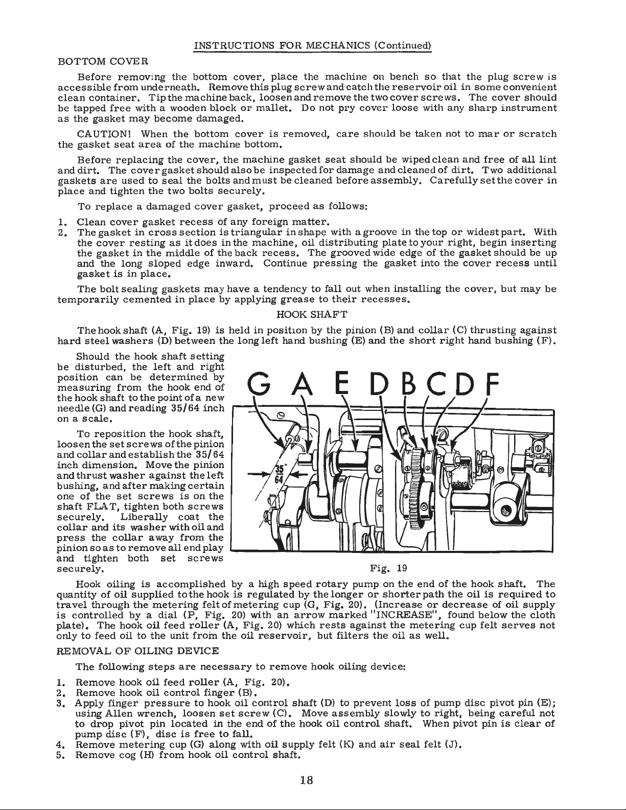
From the library of: Superior Sewing Machine & Supply LLC
INSTRUCTIONS
FOR
MECHANICS
(Continued)
BOTTOM
COVER
Before
remov
i
ng
the
bottom
cover,
place
the
machine
on
bench
so
that
the
plug
screw
is
accessible
from
underneath.
Remove
this
plug
screw
and
catch
the
reservoir
oil
in
some
convenient
clean
container.
Tipthemachineback,
loosenandremovethetwocoverscrews.
The
cover
should
be
tapped
free
with
a
wooden
block
or
mallet.
Do
not
pry
cover
loose
with
any
sharp
instrument
as
the
gasket
may
become
damaged.
CAUTION!
When
the
bottom
cover
is
removed,
care
should
be
taken
not
to
mar
or
scratch
the
gasket
seat
area
of
the
machine
bottom.
Before
replacing
the
cover,
the
machine
gasket
seat
should
be
wiped
clean
and
free
of
all
lint
and
dirt.
The
cover
gasket
should
also
be
inspected
for
damage
and
cleaned
of
dirt.
Two
additional
gaskets
are
used
to
seal
the
bolts
and
must
be
cleaned
before
assembly.
Carefully
set
the
cover
in
place
and
tighten
the
two
bolts
securely.
To
replace
a
damaged
cover
gasket,
proceed
as
follows:
1.
Clean
cover
gasket
recess
of
any
foreign
matter.
2,
The
gasket
in
cross
section
is
triangular
in
shape
with
a
groove
in
the
top
or
widest
part.
With
the
cover
resting
as
it
does
in
the
machine,
oil
distributing
plate
to
your
right,
begin
inserting
the
gasket
in
the
middle
of
the
back
recess.
The
grooved
wide
edge
of
the
gasket
should
be
up
and
the
long
sloped
edge
inward.
Continue
pressing
the
gasket
into
the
cover
recess
until
gasket
is
in
place.
The
bolt
sealing
gaskets
may
have
a
tendency
to
fall
out
when
installing
the
cover,
but
may
be
temporarily
cemented
in
place
by
applying
grease
to
their
recesses.
HOOK
SHAFT
The
hook
shaft
(A,
Fig.
19)
is
held
in
position
by
the
pinion
(B)
and
collar
(C)
thrusting
against
hard
steel
washers
(D)
between
the
long
left
hand
bushing
(E)
and
the
short
right
hand
bushing
(F).
Should
the
hook
shaft
setting
be
disturbed,
the
left
and
right
position
can
be
determined
by
measuring
from
the
hook
end
of
the
hook
shaft
to
the
point
of
a
new
needle
(G)
and
reading
35/
64
inch
on
a
scale,
To
reposition
the
hook
shaft,
loosen
the
set
screws
of
the
pinion
and
collar
and
establish
the
35/
64
inch
dimension.
Move
the
pinion
and
thrust
washer
against
the
left
bushing,
and
after
making
certain
one
of
the
set
screws
is
on
the
shaft
FLAT,
tighten
both
screws
securely.
Liberally
coat
the
collar
and
its
wash
er
with
oil
and
press
the
collar
away
from
the
pinion
so
as
to
remove
all
end
play
and
tighten
both
set
screws
E
securely.
Fig.
19
Hook
oiling
is
accomplished
by
a
high
speed
rotary
pump
on
the
end
of
the
hook
shaft.
The
quantity
of
oil
supplied
tothehook
is
regulated
by
thelonger
or
shorterpath
the
oil
is
required
to
travel
through
the
metering
felt
of
metering
cup
(G,
Fig,
20).
(Increas
e
or
decre
ase
of
oil
s
upply
is
controlled
by
a
dial
(P,
Fig
. 20)
with
an
arrow
marked
"INCREASE",
found
below
the
cloth
plat
e
),
The
hook
oil
feed
roll
er
(A,
Fig.
20) y.rhich
rests
against
th
e
metering
c
up
felt
serves
not
only
to
feed
oil
to
the
unit
froin
the
oil
reservoir,
but
filters
the
oil
as
well.
REMOVAL
OF
OILING
DEVICE
The
following
steps
are
necessary
to
remove
hook
oiling
device:
1.
R
em
ove
hook
oil
feed
roller
(A,
Fig.
20).
2.
Remove
hook
oil
control
finger
(B).
3.
Apply
finger
pr
ess
ur
e
to
hook
oil
control
shaft
(D)
to
prev
ent
loss
of
pump
disc
pivot
pin
(E);
using
Allen
wrench,
loosen
set
screw
(C).
Move
assembly
slowly
to
right,
being
careful
not
to
drop
pivot
pin
located
in
the
end
of
the
hook
oil
control
shaft.
When
pivot
pin
is
clear
of
pump
disc
(
F),
disc
is
free
to
fall.
4.
Remove
metering
cup
(G)
along
with
oil
supply
felt
(K)
and
air
seal
felt
(J).
5,
Remove
cog
(H)
from
hook
oil
control
shaft.
18
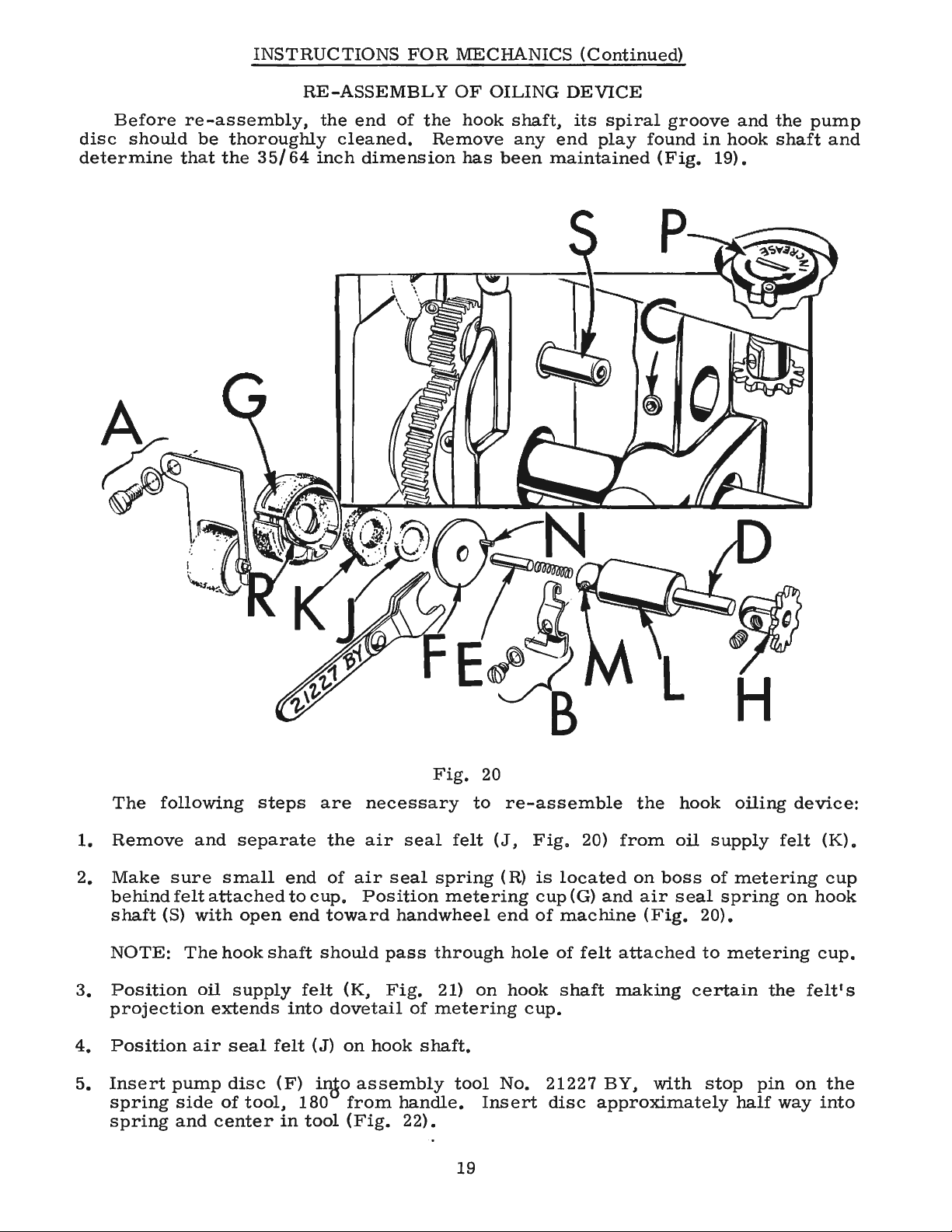
From the library of: Superior Sewing Machine & Supply LLC
INSTRUCTIONS
FOR
MECHANICS
(Continued)
RE-ASSEMBLY
OF
OILING
DEVICE
Before
re-assembly,
the
end
of
the
hook
shaft,
its
spiral
groove
and
the
pump
disc
should
be
thoroughly
cleaned.
Remove
any
end
play
found
in
hook
shaft
and
determine
that
the
35/64
inch
dimension
has
been
maintained
(Fig.
19).
Fig.
20
The
following
steps
are
necessary
to
re-assemble
the
hook
oiling
device:
1.
Remove
and
separate
the
air
seal
felt
(J,
Fig.
20)
from
oil
supply
felt
(K).
2.
Make
sure
small
end
of
air
seal
spring
(R)
is
located
on
boss
of
metering
cup
behind
felt
attached
to
cup.
Position
metering
cup
(G)
and
air
seal
spring
on
hook
shaft
(S)
with
open
end
toward
handwheel
end
of
machine
(Fig.
20).
NOTE:
The
hook
shaft
should
pass
through
hole
of
felt
attached
to
metering
cup.
3.
Position
oil
supply
felt
(K,
Fig.
21)
on
hook
shaft
making
certain
the
felt'
s
projection
extends
into
dovetail
of
metering
cup.
4.
Position
air
seal
felt
(J)
on
hook
shaft.
5.
Insert
pump
disc
(F)
inJo
assembly
tool
No.
21227
BY,
with
stop
pin
on
the
spring
side
of
tool,
180
from
handle.
Insert
disc
approximately
half
way
into
spring
and
center
in
tool
(Fig.
22).
19
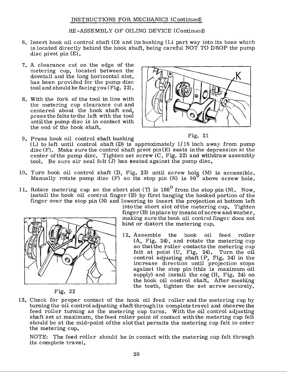
From the library of: Superior Sewing Machine & Supply LLC
INSTRUCTIONS
FOR
MECHANICS
(Continued)
RE-ASSEMBLY
OF
OILING
DEVICE
(Continued)
6.
Insert
hook
oil
control
shaft
(D)
and
its
bushing
(L)
part
way
into
its
boss
which
is
located
directly
behind
the
hook
shaft,
being
careful
NOT
TO
DROP
the
pump
disc
pivot
pin
(E).
7.
A
clearance
cut
on
the
edge
of
the
metering
cup,
located
between
the
dovetail
and
the
long
horizontal
slot,
has
been
provided
for
the
pump
disc
tool
and
should
be
facing
you
(
Fig.
22).
8.
With
the
fork
of
the
tool
in
line
with
the
metering
cup
clearance
cut
and
centered
about
the
hook
shaft
end,
press
the
felts
to
the
left
with
the
tool
until
the
pump
disc
is
in
contact
with
the
end
of
the
hook
shaft.
9.
Press
hook
oil
control
shaft
bushing
Fig.
21
(L)
to
left
until
control
shaft
(D)
is
approximately
1/
16
inch
away
from
pump
disc
(F).
Make
sure
the
control
shaft
pivot
pin(E)
seats
in
the
depression
at
the
center
ofthe
pump
disc.
Tighten
set
screw
(C,
Fig.
22)
and
withdraw
assembly
tool.
Be
sure
air
seal
felt
(J)
has
seated
against
the
pump
disc.
10.
Turn
hook
oil
control
shaft
(D,
Fig.
23)
until
screw
hol
0
(M)
is
accessible.
Manually
rotate
pump
disc
(F)
so
its
stop
pin
(N)
is
90
above
screw
hole.
11.
Rotate
metering
cup
so
the
short
slot
(T)
is
180°
from
the
stop
pin
(N).
Now,
install
the
hook
oil
control
finger
(B)
by
first
hanging
the
hooked
portion
of
the
finger
over
the
stop
pin
(N)
and
lowering
to
insert
the
projection
at
bottom
left
Fig.
22
into
the
short
slot
of
the
metering
cup.
Tighten
finger
(B)
in
place
by
means
of
screw
and
washer,
making
sure
the
hook
oil
control
finger
does
not
bind
or
distort
the
metering
cup.
12.
Assemble
the
hook
oil
feed
roller
(A,
Fig.
24),
and
rotate
the
metering
cup
so
that
the
roller
contacts
the
metering
cup
felt
at
point
(U,
Fig.
24).
Turn
the
oil
control
adjusting
shaft
(
P,
Fig.
24)
in
the
increase
direction
until
projection
stops
against
the
stop
pin
(this
is
maximum
oil
supply)
and
install
the
cog
(H,
Fig.
24)
on
the
hook
oil
control
shaft.
After
meshing
the
teeth,
tighten
the
set
screw
securely.
13.
Check
for
proper
contact
of
the
hook
oil
feed
roller
and
the
metering
cup
by
turningthe
oil
control
adjusting
shaftthroughits
complete
travel
and
observe
the
feed
roller
turning
as
the
metering
cup
turns.
With
the
oil
control
adjusting
shaft
set
at
maximum,
the
feed
roller
point
of
contact
with
the
metering
cup
felt
should
be
at
the
mid-point
of
the
slot
that
permits
the
met
e
ring
cup
felt
to
enter
the
metering
cup.
NOTE:
The
feed
roller
should
be
in
contact
with
the
metering
cup
felt
through
its
complete
travel.
20
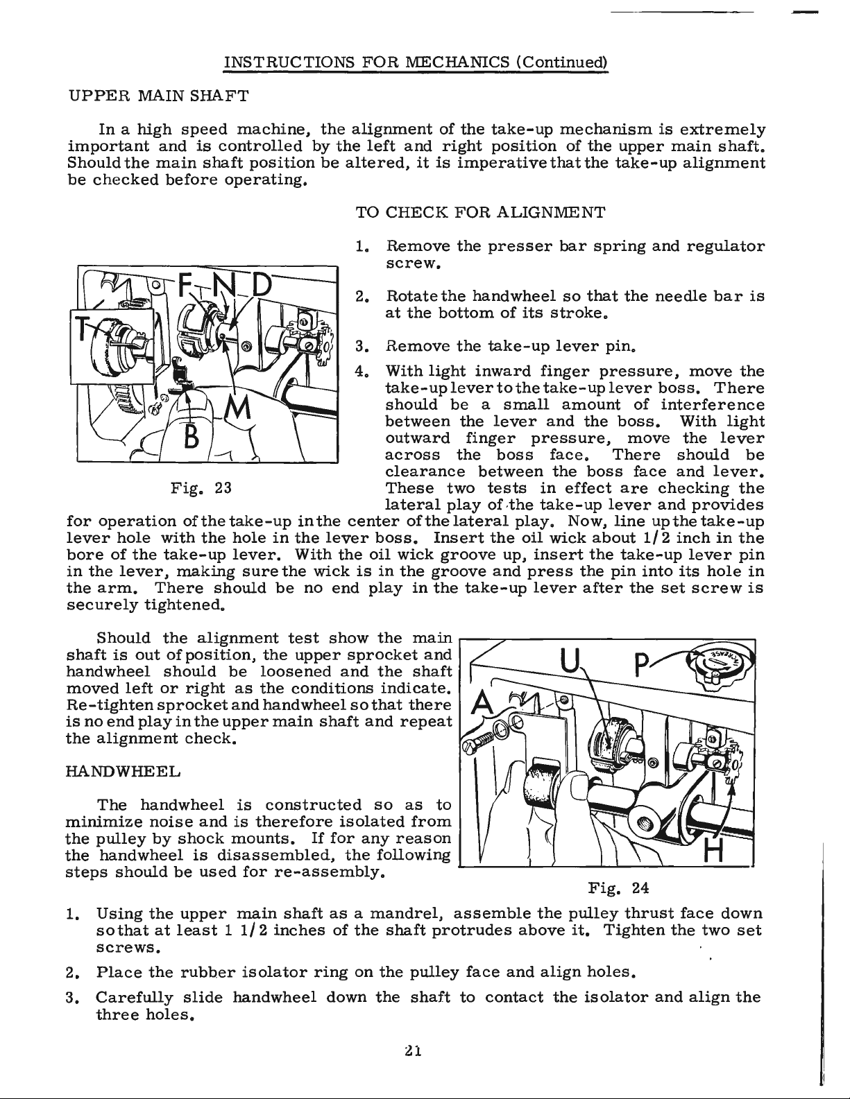
From the library of: Superior Sewing Machine & Supply LLC
INSTRUCTIONS
FOR
MECHANICS
(Continued)
UPPER
MAIN
SHAFT
In
a
high
speed
machine,
the
alignment
of
the
take-up
mechanism
is
extremely
important
and
is
controlled
by
the
left
and
right
position
of
the
upper
main
shaft.
Should
the
main
shaft
position
be
altered,
it
is
imperative
that
the
take-up
alignment
be
checked
before
operating.
TO
CHECK
FOR
ALIGNMENT
1.
Remove
the
presser
bar
spring
and
regulator
screw.
2.
Rotate
the
hand
wheel
so
that
the
needle
bar
is
at
the
bottom
of
its
stroke.
3.
Remove
the
take-up
lever
pin.
4.
With
light
inward
finger
pressure,
move
the
take-up
lever
to
the
take-up
lever
boss.
There
should
be
a
small
amount
of
interference
between
the
lever
and
the
boss.
With
light
outward
finger
pressure,
move
the
lever
across
the
boss
face.
There
should
be
clearance
between
the
boss
face
and
lever.
Fig.
23
These
two
tests
in
effect
are
checking
the
lateral
play
of
,the
take-up
lever
and
provides
for
operation
of
the
take-up
in
the
center
of
the
lateral
play.
Now,
line
up
the
take-up
lever
hole
with
the
hole
in
the
lever
boss.
Insert
the
oil
wick
about
1/
2
inch
in
the
bore
of
the
take-up
lever.
With
the
oil
wick
groove
up,
insert
the
take-up
lever
pin
in
the
lever,
making
sure
the
wick
is
in
the
groove
and
press
the
pin
into
its
hole
in
the
arm.
There
should
be
no
end
play
in
the
take-up
lever
after
the
set
screw
is
securely
tightened.
Should
the
alignment
test
show
the
main
r----:;;;,----
-
-----
--:
:::====:::~
shaft
is
out
of
position,
the
upper
sprocket
and
handwheel
should
be
loosened
and
the
shaft
moved
left
or
right
as
the
conditions
indicate.
Re-tighten
sprocket
and
hand
wheel
so
that
there
is
no
end
play
in
the
upper
main
shaft
and
repeat
the
alignment
check.
HANDWHEEL
The
handwheel
is
constructed
so
as
to
minimize
noise
and
is
therefore
isolated
from
the
pulley
by
shock
mounts.
If
for
any
reason
the
handwheel
is
disassembled,
the
following
steps
should
be
used
for
re-assembly.
,.___
__
____..___.L..-
_
____._.,
_ "--_,__
____
,
Fig.
24
1.
Using
the
upper
main
shaft
as
a
mandrel,
assemble
the
pulley
thrust
face
down
so
that
at
least
1
1/
2
inches
of
the
shaft
protrudes
above
it.
Tighten
the
two
set
screws.
2.
Place
the
rubber
isolator
ring
on
the
pulley
face
and
align
holes.
3.
Carefully
slide
handwheel
down
the
shaft
to
contact
the
isolator
and
align
the
three
holes.
21

From the library of: Superior Sewing Machine & Supply LLC
INSTRUCTIONS
FOR
MECHANICS (
Continued)
HAND
WHEEL
(
Continued)
4.
Three
plastic
"O"
rings
are
now
inserted
into
their
respective
holes
in
the
handwheel.
5.
The
outer
isolator
ring
and
cap
are
now
assembled.
6.
Insert
the
three
screws
that
are
run
through
the
complete
assembly
and
tightened
lightly.
7.
Loosen
the
two
pulley
screws
and
slowly
revolve
the
whole
assembly
several
times
for
good
alignment.
Now.
gradually
tighten
the
three
screws
moving
from
one
to
the
other
until
all
are
snug.
8.
The
assembly
should
run
true
as
it
revolves
freely
on
the
shaft.
If
any
sidewise
run-out
is
noted,
it
can
be
corrected
by
slight
changes
of
screw
pressure
in
the
three
iso-
lator
screws.
CAUTION!
When
replacing
the
handwheel
assembly
on
the
mainshaft,
care
must
be
taken
Fig.
25
not
to
damage
the
oil
seal
located
near
the
end
of
the
shaft.
The
surface
of
the
ring
should
be
lightly
oiled
and
the
handwheel
worked
over
the
seal
gently.
Upper
main
shaft
should
be
held
securely
to
the
right
when
sliding
handwheel
over
seal
to
prevent
damage
to
the
take-up
mechanism.
STITCH
LENGTH
INDICATOR
After
a
feed
timing
change,
the
stitch
length
indicator
will
have
to
be
re-adjusted
to
read
accurately.
1.
Depress
the
stitch
length
change
button
until
it
engages
in
the
feed
eccentric.
2.
Turn
the
handwheel
toward
you
until
the
stop
is
reached,
indicating
the
longest
stitch
length.
3.
Loosen
the
stitch
length
indicator
set
screws.
4.
With
the
change
button
still
engaged,
set
the
indicator
dial
to
read
"L"
in
the
-
window
on
the
belt
guard.
5.
Tighten
indicator
dial
set
screws.
TIMING
THE
MACIDNE
Tip
the
machine
back
against
the
rest
:r.in
and
turn
handwheel
until
the
needle
bar
is
at
the
top
of
its
stroke.
The
timing
line
'4"
on
the
feed
drive
eccentric
should
line
up
with
the
mark
on
the
wall
of
the
casting
(A,
Fig.
25).
22

From the library of: Superior Sewing Machine & Supply LLC
INSTRUCTIONS
FOR
MECHANICS
(Continued)
TO
SET
THE
FEED
TIMING
1.
Remove
the
needle
from
the
needle
bar.
2.
Remove
large
plug
screws
below
the
oil
gauge
and
below
the
handwheel.
3.
Turn
the
handwheel
until
the
needle
bar
is
at
the
top
of
its
stroke.
4.
Loosen
the
lower
sprocket
screws
through
the
hole
below
the
oil
gauge.
5.
Hold
the
handwheel
securely
and
turn
the
lower
main
shaft
until
the
timing
line
11
4
11
on
the
adjustable
feed
driving
eccentric
and
mark
on
the
casting
wall
line
up
(A,
Fig.
25).
6.
Press
the
lower
main
shaft
firmly
toward
the
handwheel
and
with
a
screwdriver,
press
the
lower
sprocket
toward
the
head
of
the
machine.
Through
the
access
hole.
retighten
the
two
sprocket
screws
securely.
There
should
be
no
end
play
in
the
lower
main
shaft.
7. A
small
quantity
oflead
seal
should
be
applied
on
the
threads
of
both
plug
screws
before
they
are
replaced.
CAUTION!
After
any
feed
timing
change,
the
hook
must
be
retimed.
LOWER
MAIN
SHAFT
Should
the
lower
main
shaft
position
be
altered,
it
is
important
that
the
collar
(61432
J).
located
between
the
hook
driving
gear
and
the
left
lower
main
shaft
bushing.
be
located
.
020
inch
from
the
bushing.
The
belt
should
be
assembled
on
the
lower
sprocket
so
that
the
second
set
screw
is
accessible
through
the
large
plug
screw.
HEAD
MECHANISM
LUBRICATION
ADJUSTMENT
The
needle
bar
link
(A.
Figs.
26, 27)
is
lubricated
at
two
points.
Fig.
27
1.
Thrust
washer
(B.
Fig.
26)
must
be
positioned
so
that
oil
wick
(C)
wipes
across
the
thin
portion
of
the
thrust
washer.
Washer
is
positioned
by
loosening
left
hand
screw
(D).
2.
Position
bracket
by
means
of
screw
Fig.
26
(B,
Fig.
27)
so
that
wick
(C)
passes
through
the
center
of
the
slot
in
needle
bar
link
(A).
Wick
(C)
must
contact
the
needle
bearings.
Proper
wick
contact
with
the
needle
bearings
can
be
obtain-
ed
by
bending
the
wick
support
bracket
(D)
closer
or
far-
ther
away
from
the
needle
bar
link
as
required.
Be
sure
to
secure
the
felt
strip
(E)
to
the
upper
needle
bar
bush-
ing
with
spring
clip
61454
B.
23

From the library of: Superior Sewing Machine & Supply LLC
24
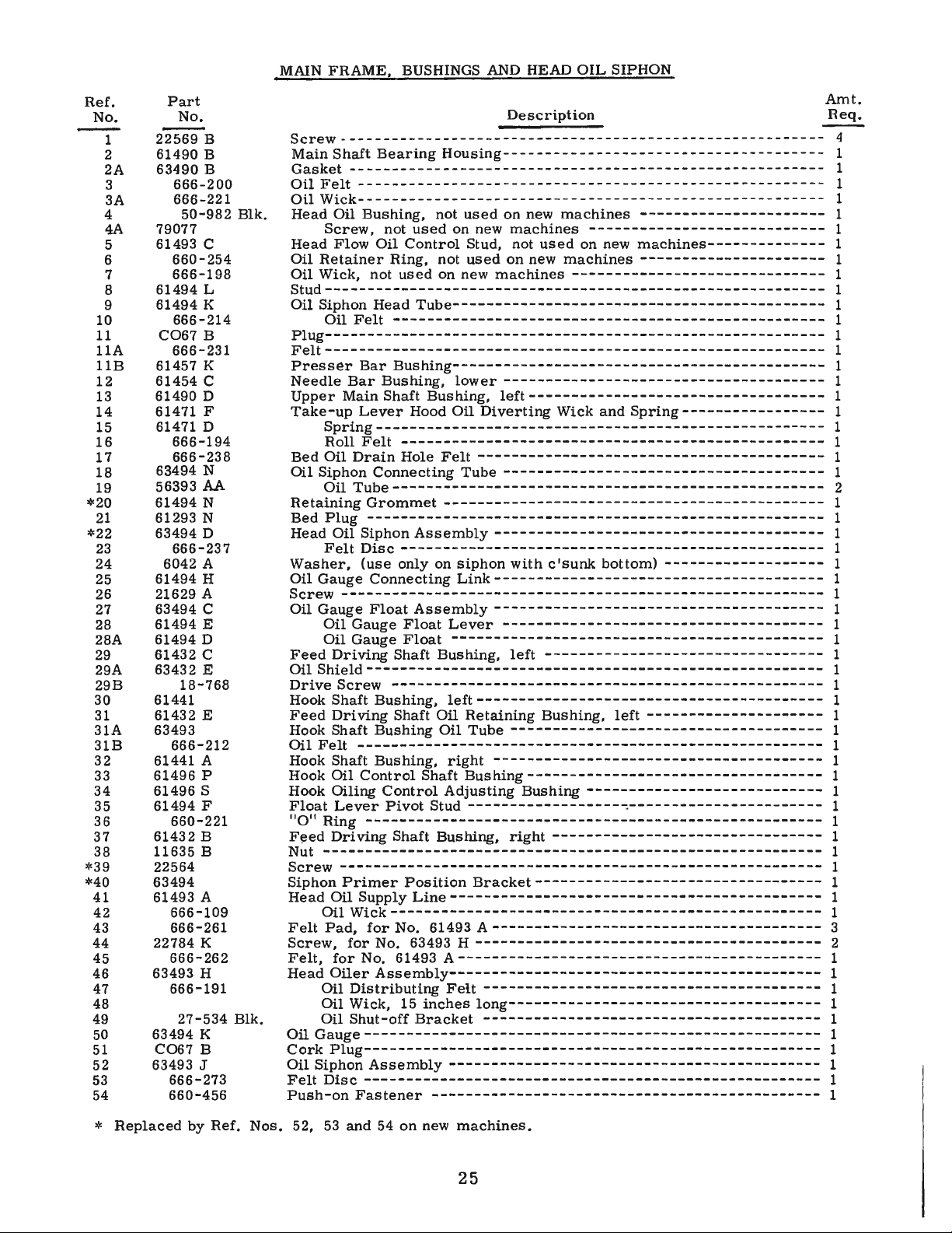
From the library of: Superior Sewing Machine & Supply LLC
Ref.
No.
1
2
2A
3
3A
4
4A
5
6
7
8
9
10
11
llA
llB
12
13
14
15
16
17
18
19
*20
21
*22
23
24
25
26
27
28
28A
29
29A
29B
30
31
31A
31B
32
33
34
35
36
37
38
*39
*40
41
42
43
44
45
46
47
48
49
50
51
52
53
54
Part
No.
22569 B
61490 B
63490
B
666-200
666-221
50-982 Blk.
79077
61493 C
660-254
666-198
61494 L
61494
K
666-214
CO67 B
666-231
61457
K
61454 C
61490 D
61471 F
61471 D
666-194
666-238
63494 N
56393
AA
61494 N
61293 N
63494 D
666-237
6042 A
61494 H
21629 A
63494 C
61494
E
61494 D
61432 C
63432
E
18-768
61441
61432
E
63493
666-212
61441 A
61496 P
61496 S
61494 F
660-221
61432 B
11635 B
22564
63494
61493 A
666-109
666-261
22784
K
666-262
63493
H
666-191
27-534 Blk.
63494
K
CO67 B
63493
J
666-273
660-456
MAIN
FRAME, BUSHINGS
AND
HEAD OIL SIPHON
Amt.
Description
Req.
Screw---------------------------------------------------------
4
Main Shaft
Bearing
Housing--------------------------------------
1
Gasket-----------------
-
--------------------------------------
1
Oil
Fell-------------------------------------------------------
1
Oil
Wick--- - - --
--
- ---
--
---- - - --- - - -
--
- -
--
- --- - - --- - - -
-- --
--
- - -- 1
Head Oil Bushing, not
used
on
new
machines
----------------------
1
Screw,
not
used
on
new
machines
----------------------------
1
Head Flow Oil
Control
Stud, not
used
on new
machines--------------
1
Oil
Retainer
Ring, not
used
on new
machines
----------------------
1
Oil Wick, not
used
on new
machines
------------------------------
1
Stud-----------------------------------------------------------
1
Oil Siphon Head
Tube--------------------------------------------
1
Oil
Felt---------------------------------------------------
1
Plug-----------------------------------------------------
-
-----
1
Felt-----------------------------------------------------------
1
Presser
Bar
Bushing--------------------------------------------
1
Needle
Bar
Bushing,
lower--------------------------------------
1
Upper
Main Shaft Bushing,
left-----------------------------------
1
Take-up
Lever
Hood Oil
Diverting
Wick and
Spring-----------------
1
Spring-----------------------------------------------------
1
Roll
Felt--------------------------------------------------
1
Bed Oil
Drain
Hole
Felt
-----------------------------------------
1
Oil Siphon Connecting Tube
--------------------------------------
1
Oil
Tube---------------------------------------------------
2
Retaining
Grommet
---------------------------------------------
1
Bed
Plug------------------------------------------------------
1
Head Oil Siphon
Assembly---------------------------------------
1
Felt
Disc--------------------------------------------------
1
Washer,
(use
only on
siphon
with
c'sunk
bottom)
-------------------
1
Oil Gauge Connecting
Link---------------------------------------
1
Screw---------------------------------------------------------
1
Oil Gauge
Float
Assembly
---------------------------------------
1
Oil Gauge
Float
Lever
--------------------------------------
1
Oil Gauge
Float--------------------------------------------
1
Feed
Driving
Shaft Bushing,
left
---------------------------------
1
Oil
Shield------------------------------------------------------
1
Drive
Screw---------------------------------------------------
1
Hook Shaft Bushing,
left-----------------------------------------
1
Feed
Driving
Shaft Oil Retaining Bushing,
left
---------------------
1
Hook Shaft Bushing Oil Tube
-------------------------------------
1
Oil
Felt-------------------------------------------------------
1
Hook Shaft Bushing,
right
---------------------------------------
1
Hook Oil
Control
Shaft
Bushing-----------------------------------
1
Hook Oiling
Control
Adjusting Bushing
----------------------------
1
Float
Lever
Pivot
Stud
-------------------::-----------------------
1
11
0
11
Ring------------------------------------------------------
1
F!:!ed
Driving Shaft Bushing,
right
--------------------------------
1
Nut-----------------------------------------------------------
1
Screw---------------------------------------------------------
1
Siphon
Primer
Position
Bracket----------------------------------
1
Head Oil Supply
Line--------------------------------------------
1
Oil
Wick---------------------------------------------------
1
Felt
Pad,
for
No. 61493
A---------------------------------------
3
Screw,
for
No. 63493 H
-----------------------------------------
2
Felt,
for
No. 61493
A-------------------------------------------
1
Head
Oiler
Assembly--------------------------------------------
1
Oil
Distributing
Feit
----------------------------------------
1
Oil Wick,
15
inches
long-------------------------------------
1
Oil Shut-off
Bracket
----------------------------------------
1
Oil
Gauge------------------------------------------------------
1
Cork
Plug------------------------------------------------------
1
Oil Siphon
Assembly
------------
---
--
---
-----
---------
--
--------
1
Felt
Disc------------------------------------------------------
1
Push-on
Fastener----------------------------------------------
1
*
Replaced
by Ref. Nos. 52,
53
and
54
on new
machines.
25

From the library of: Superior Sewing Machine & Supply LLC
514
51-A
__
,..---..
26
 Loading...