


63400X
INDUSTRIAL
From the library of: Superior Sewing Machine & Supply LLC
SEWING
®
EST
QUALITY
STYLES
63400X
63400Y
63400KX
63400KY
C 0 L U M B I
A®
MACHINES
ATALOG
No.
121KX
Second
Edition
CL
ASS
S
TREAMLINED
HIGH SPEED
LOCKSTIT
WITH
INTERMITTENT
UNION SPECIAL
63400
CH
REVERS
MACHINES
FEED
CORPORATION
C H
ICAGO
(Supplement
From the library of: Superior Sewing Machine & Supply LLC
Catalog
to
No.
Catalog
INSTRUCTIONS
FOR
121
KX
No.
121
M)
ADJUSTING
LIST
Streamlined
63400
634
00
Second
AND
OF
CLASS
Styles
X
KX
OPERATING
PARTS
63400
Lockstitch
63400
63400
Edition
Y
KY
Copyright
1969
by
Union
Rights
Specia
Reserved
1
Corporation
in
All
Countries
UNION SPECIAL CORPORATION
INDUSTRIAL
Print
SEWING
CHIC
e d
in
2
A
MACHINES
GO
U.
S.
A .
July.
1977
IDENTIFICATION
From the library of: Superior Sewing Machine & Supply LLC
OF
MACHINES
Each
on
the
machine.
Style
numbers
Example:
minor
Style
changes
number.
Styles
which
63400
differs
11
•
This
junction
KY,
book.
the
therewith.
but
not
For
63400 X and
Opposite
number,
NOTE:
description,
When
column.
Adjusting
similarto
instructions
and
B,
or
KX, Y
and
UNION
have
"Style
are
Example:
of
machines
from
catalog
used
clarity,
the
ordering
and
those
included
are
additional
KY.
SPECIAL
Style
one
63400
made
machine
numbers
or
more
X".
Special
in
a
"Style
similar
the
style
number,
APPLICATION
is a supplement
Only
on
certain
KX, Y
Styles
and
those
63400 A or B are
63400 A or B parts
KY
illustration
and
amount
repair
operating
inCatalog
in
this
instructions
No.
catalog
instructions
is
are
letters
Style
standard
63400
in
construction
to
parts
which
parts.
page,
required.
parts
always
121M
are
identified
classified
suffixed,
numbers
machine,
XZ
".
by a Style
as
but
contain
a"
are
in
that
it
contains
OF
CATALOG
Catalog
are
No.
used
121 M
illustrated
are
parts
use
for
are
the
Styles
identified
forStyles63400A
the
ones
that
that
pertain
specifically
number
standard
never
and
contain
the
Z"
is
suffixed
grouped
no
letters.
and
should
on
Styles
and
shown
63400 X and
listed
in
phantom
by
part
number
63400 X and
and
Brespectively.
are
different
on a name
special.
the
letter
letter
"Z
to
".
the
When
under a class
Example:
be
used
KX, Y
at
the
back
to
help
detail
listed
from
to
Styles
number,
in
KX, Y
Styles
the
and
63400 X and
plat
Standard
"Z
".
only
Standard
number
"Class
in
con-
and
of
this
locate
part
second
KY
are
The
only
63400 A
e
The
catalog
herein.
in
this
given
of
handwheel
High
and
Hook,
System,
Needle
Needle
to
Right
It
class.
from
Speed
Plain
Horizontal
Head
Bearing
Bar
of
can
Feed,
Needle
63400 X For
medium
1
9/64
needle.
size,
speed
needle
5500
63400 Y For
to
medium
tacking.
or
180
GYS
inch,
thread
recommended
applies
also
be
Reference
the
operator's
is
toward
Streamlined
One
Hook
Oil
Siphon,
Adjustable
Driving
Link,
Bar
attaching
weight
inch
Specify
material,
needle
presser
type
R.
P.
M. -
attaching
heavy
113/64
inch
needle.
size,
speed
specifically
applied
to
position
the
operator.
Long
Needle,
Shaft,
Adjustable
Feed
Feed
11
1/8
pockets
bar
travel.
and
size,
depending
pockets
weight
needle
Specify
needle
5500 R.
with
direction,
while
STYLES
Arm
Lockstitch
Light,
One
Eccentric,
Timing
inches.
to
shirt
where
Seam
foot,
throat
attachment
to
shirt
material,
bar
presser
type
P.
M. -
to
the
discretion
such
seated
OF
MACHINES
Medium
Reservoir
Hook
Needle
on
Lower
fronts
reverse
Spec.
plate,
on
operation.
fronts
where
travel.
foot,
and
size,
depending
Standard
to
some
as
right,
at
the
Machines,
and
Heavy
Enclosed
Oil
Control,
Beari~gs
Main
and
feed
can
301-SSa-1.
feed
and
guide.
and
similar
reverse
Seam
Spec.
throat
attachment
on
Styles
Special
left,
machine.
with
Duty,
Automatic
Shaft,
similar
be
Type
dog,
stitches
Maximum
feed
301-SSa-1.
plate,
operation.
of
machines
Styles
front,
back,
Operating
Intermittent
Drop
Automatic
for
Take-up
Maximum
operations
used
for
183
GXSor
per
operations
can
be
used
feed
and
dog,
guide.
as
listed
of
machines
etc. , are
direction
Reverse
Feed,
Rotary
Lubricating
Head
Lever
Work
on
light
Oiling,
and
Space
back-tacking.
183 GYS
inch,
thread
recommended
on
medium
for
back-
Type
180 GXS
stitches
per
Maximum
to
3
STYLES
From the library of: Superior Sewing Machine & Supply LLC
OF
MACinNES
(Continued)
63400
KX
trimmer)
63400
KY
trimmer)
NOTE:
Styles
able
this
63400 A and
for
catalog.
Each
type
tails.
the
number
The
blade
number
Needle
Needle
Their
Type
180
180
description
No.
GXS
GYS
183 GXS
183
GYS
Same
Same
The
as
and
as
and
same
Style
Thread
Style
Thread
sewing
B,
use
on
Styles
UNION
SPECIAL
denotes
size
number,
measured
and
the
Type
Type
183
in
size
180
GXS
and
Round
groove,
ium
shank,
wide
plated -sizes
125/049, 140/054,
Round
shank,
groove,
-sizes
075/029,080/032,090/036,100/040,
150/060.
Round
single
shank,
groove,
chromium
110/044.
Round
single
plated-
shank,
groove,
sizes
63400
Wiper.
63400
Wiper.
parts
can
be
63400
the
kind
stamped
thousandths
number
GXS
or
or
183
the
sizes
round
angle
round
wide
angle
round
wide
plated-
round
wide
075/029,
X,
except
Prepared
Y,
except
Prepared
(presser
used
KX
needle
and
of
on
has
shank,
on
of
represent
180
GYS
GYS
available
Description
point,
groove,
075/029,
150/060.
point,
groove,
point,
angle
sizes
point,
angle
equipped
for
Needle
equipped
for
Needle
foot,
Styles
KY
63400 X andY.
are
illustrated
NEEDLES
both a type
point,
the
needle
an
inch
the
are
recommended
are
recommended
are
length,
shank,
across
complete
listed
and
Sizes
lockstitch,
struck
groove,
080/032,
lockstitch,
struck
groove,
lockstitch,
groove,
struck
065/025,075/029,
lockstitch,
groove,
080/032,
struck
090/036,
with
with
throat
number
below.
short
short
"KLIPP-
Positioner.
"KLIPP-IT"
Positioner.
plate
The
and
described
and a size
groove,
denotes
the
eye.
symbol.
for
Styles
for
Styles
length,
deep
spot,
090/036,
length,
deep
spot,
110/044,
extra
short
groove,
080/032,
extra
short
groove,
100/040,
IT"
(Thread
(Thread
and
feed
dog)
sewing
at
number.
finish
and
largest
Collectively,
63400 Y and
63400 X
ball
ball
point,
100/040,
ball
chromium
125/049,
length,
deep
spot,
090/036,
length,
deep
spot,
110/044.
Under-
Under
used
parts
the
avail
back
other
diameter
the
and
eye,
single
chrom-
110/044
eye,
single
plated
140/054,
ball
ball
point,
100/040,
ball
chromium
-
on
-
of
The
de-
of
type
KY.
KX.
,
eye,
eye,
To
sample
onlabel.
Selection
Thread
have
needle,
should
needle
or
Acomplete
of
proper
pass
orders
the
type
orderwould
needle
freely
promptly
and
size
read:
size
through
and
number
"1000
should
the
needle
accurately
should
Needles,
be
determined
eye
in
formation.
The
size
of
upon
the
The
size
and
referred
smaller
strength
the
thread
size
table
kind
to
above,
than
requirement
of
the
on
the
of
thread.
the
size
SELECTING
employed.
needle
employed.
following
The
which
may
specified.
THE
of
the
The
page
choice,
dictate
SIZE
seam
quality
shows
however,
the
OF
produced
of
the
the
preferred
should
selection
4
THE
work
of a needle
filled,
be
forwarded.
an
Type180GXS,
by
the
order
to
produce a good
NEEDLE
is
largely
desired
give
is
siz
~
consideration
size
empty
Use
Size080/032
size
of th_
dependent
largely
of
needle
slightly
package,
description
...
ead
11
used.
stitch
upon
the
dependent
for a given
to
factors
larger
or
a
Cotton
From the library of: Superior Sewing Machine & Supply LLC
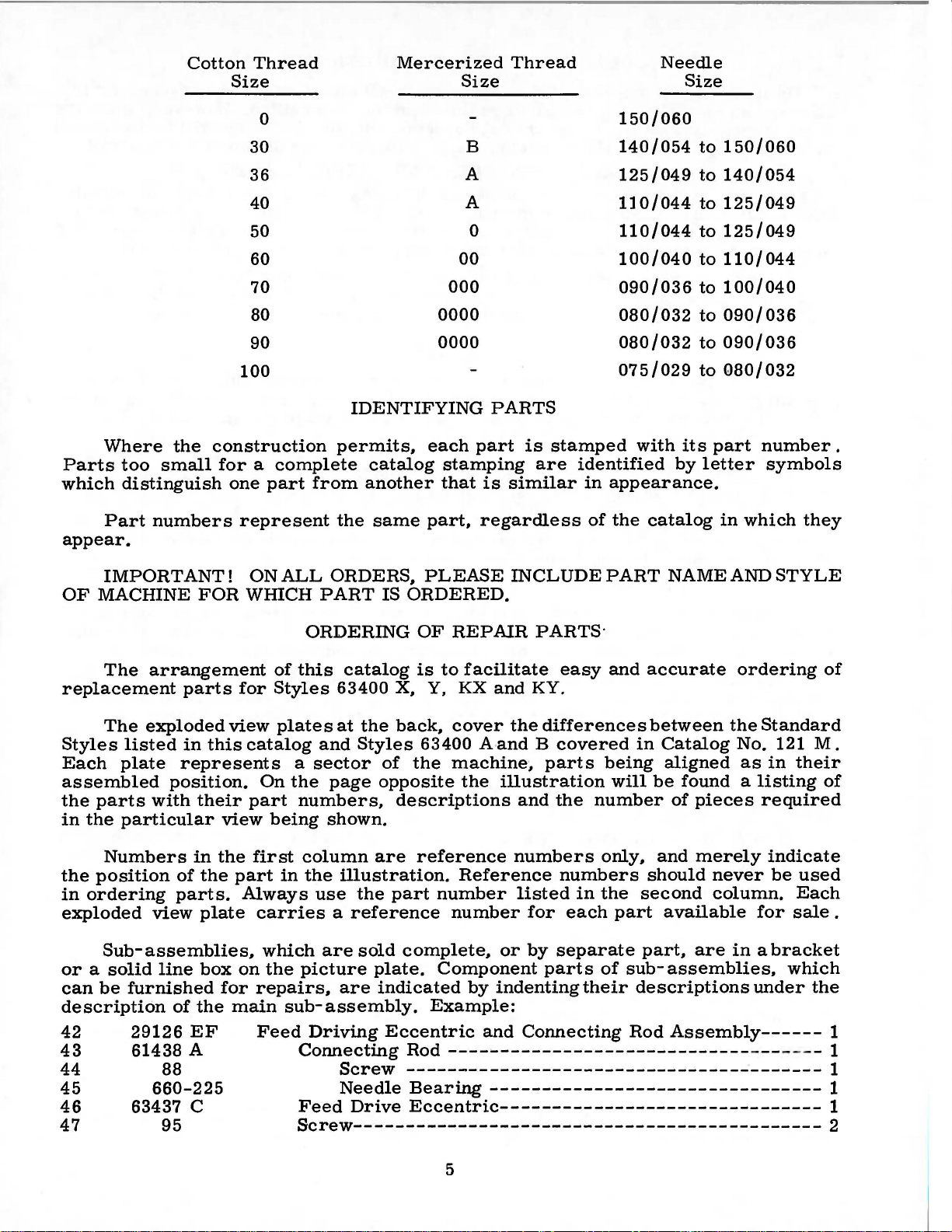
Size
Thread
Mercerized
Size
Thread
Needle
Size
Where
Parts
which
Part
appear.
the
too
small
distinguish
numbers
0
30
36
40
50
60
70
80
90
100
construction
for a complete
one
part
from
represent
0000
0000
IDENTIFYING
permits,
catalog
another
the
same
each
stamping
that
part,
B
A
A
0
00
000
PARTS
part
is
regardless
is
stamped
are
similar
150/060
140/054
125/049
110/044
110/044
100/040
090/036
080/032
080/032
075/029
with
identified
in
appearance.
of
the
catalog
its
by
to
150/060
to
140/054
to
125/049
to
125/049
to
110/044
to
100/040
to
090/036
to
090/036
to
Q80/032
part
letter
in
number.
symbols
which
they
IMPORTANT!
OF
MACHINE
The
arrangement
replacement
The
exploded
Styles
Each
listed
plate
assembled
the
in
parts
the
with
particular
Numbers
the
position
in
ordering
exploded
view
Sub-assemblies,
or a solid
can
be
furnished
description
42
43
29126
61438 A
44
45
46
660-225
63437 C
47
FOR
parts
in
this
represents
position.
their
in
of
the
parts.
plate
line
box
of
the
EF
88
95
WIDCH
for
view
catalog
part
view
the
part
Always
on
for
main
ONALL
of
Styles
plates
On
being
first
in
carries
which
the
repairs,
Feed
ORDERS,
PART
IS
ORDERING
this
catalog
63400
at
and
a
sector
the
page
numbers,
X, Y, KX
the
back,
Styles
of
opposite
descriptions
shown.
column
the
use
are
picture
are
illustration.
the
part
a
reference
sold
plate.
are
indicated
sub-assembly.
Driving
Eccentric
Connecting
Screw
Needle
Feed
Drive
PLEASE
INCLUDEPART
ORDERED.
OF
REPAIR
is
to
facilitate
cover
63400 A-and B
the
machine,
the
reference
Reference
number
number
complete,
Component
by
PARTS·
easy
and
KY.
the
differences
covered
parts
illustration
and
the
numbers
numbers
listed
for
or
by
separate
parts
indenting
Example:
and
Connecting
Rod
-----------------------------
---------------------------------------Bearing
--------------------------------
Eccentric-------------------------------
Screw---------------------------------------------
number
in
each
their
and
accurate
between
in
being
will
be
only,
and
should
the
second
part
part,
of
sub-
descriptions
Rod
NAMEANDSTYLE
ordering
the
Standard
Catalog
aligned
No. 121
as
in
their
found a listing
of
pieces
merely
never
column.
available
are
assemblies,
required
indicate
be
used
Each
for
sale
in a bracket
which
under
the
Assembly------
---- - - - 1
of
M.
of
.
1
1
1
1
2
5

In
From the library of: Superior Sewing Machine & Supply LLC
catalog,
PC\,rts
in
for
the
Success
UNION
ration,
to
the
those
cases
no
specific
the.
v~rious
descr1pt1on,
in
the
SPECIAL
its
subsidiaries
most
approved
ORDERING
where a part
usage
ma?hines
and,
1f
necessary,
USE
GENUINE
operation
Needles
and
and
scientific
OF
will
be
are
of
Repair
authorized
principles,
REP
AIR
is
common
mentioned
not
the
the
d1fference
NEEDLES
these
machines
Parts
distributors.
PARTS
to
in
s.ame,
AND
as
furnished
and
(Continued)
all
of
the
description.
the
specific
w1ll
REPAIR
can
are
made
the
be
be
by
They
machines
usag~
shown
PARTS
secured
the
Union
are
with
utmost
covered
However,
will
~e
1n
the
lllustratlon.
only
with
Special
designed
precision.
by
this
when
men
the
ti~ned
genuine
Corpo-
according
Genuine
pair
parts
mark
is
are
your
Prices
are
forwarded
otherwise
directed.
CAUTION!
on
handwheel.
Before
carefully
packing
A
attaching
packed.
box,
bag
of
screw,
miscellaneous
The
bag
chronizer
lead
wire
bracket,
clamp
needles
are
stamped
guarantee
are
strictly
f. o.
b.
A
When
Using
leaving
both
factory,
After
the
following
PREPARATION
assembly
one
attachment
of
assembly
one
and
three
packaged
with
the
of
the
highest
net
cash
shipping
charge
is
unpacking,
hands
each
the
machine
steps
parts,
extra
bobbin,
to
the
parts
synchronizer
clamps
with
Union
Special
quality
TERMS
and
subject
point.
made
Parcel
to
INSTALLING
DO
NOT
on
bed
casting,
Union
Special
and
should
OF
be
MACHINE
consisting
two
bed
plate,
for
Styles
lead
for
tension
labels
marked~.
trademark,
in
materials
to
change
Post
cover
lift
the
machine
lift
machine
accessories
followed:
FOR
of
one
hinge
are
studs,
packed
63400
wire
clamp,
release
U S
and
without
notice.
shipments
postage
out
of
and
box
gently.
is
sewed
have
been
INSTALLATION
frame
KX
and
with
and
thread
KY
one
two
each
also
screw
solenoid
Genuine
Emblem.
Each
workmanship.
All
are
insured
insurance.
by
placing
off,
inspected
removed
eyelet,
screws
for
machine.
include
for
synchronizer
lead
wire.
re-
trade-
shipments
unless
one
hand
and
from
one
the
eyelet
holding
one
syn-
Insert
the
(4)
1.
2.
3.
4.
upper
For
steps:
Attach
(376
Attach
Slide
Attach
frame
Styles
A)
clamp
STANDARD
Included
ing
one
bobbin
its
clamp
and
screw,
essential
TABLE
spring,
when
TOPS
Lockstitch
the
bed
plate
hinge
the
studs
eyelet
63400
synchronizer
screws.
in
to
KX
The
synchronizer
(660-356)
clamp
to
synchronizer
ACCESSORIES
also
with
each
four
winder
isolator
setting
one
assembly,
knee
up
machines
is
FLUSH
with
holes
top
and
upper
to
adaptor
over
machine
lifter
pads
the
are
the
provided
of
arm
(A,
KY,
use
bracket
screw
of
synchronizer
bracket
is a box
the
machine
assembly
and
clips,
machine.
installed
top
of
for
them
Fig.
Fig.
(63495
also
2A).
lA
D)
to
handwheel
lead
using
of
mounting
and
its
and
one
in
table
the
machine
6
in
rear
as a guide
to
the
back
hold
clamp
assembly
wire.
(J87
J)
screw.
STANDARD
frame,
rubber
machine
tops,
pad,
rest
prepared
mounting
of
cloth
to
complete
of
plate.
machine,
(660-352)
using
the
two
ACCESSORIES-
one
oil
drain
bed
positioning
pin.
These
with
cut-out,
frame.
Assemble
the
following
using
in
position.
set
screws.
contain-
parts
jar
and
spring
are
so
that
two
MACHINE
From the library of: Superior Sewing Machine & Supply LLC
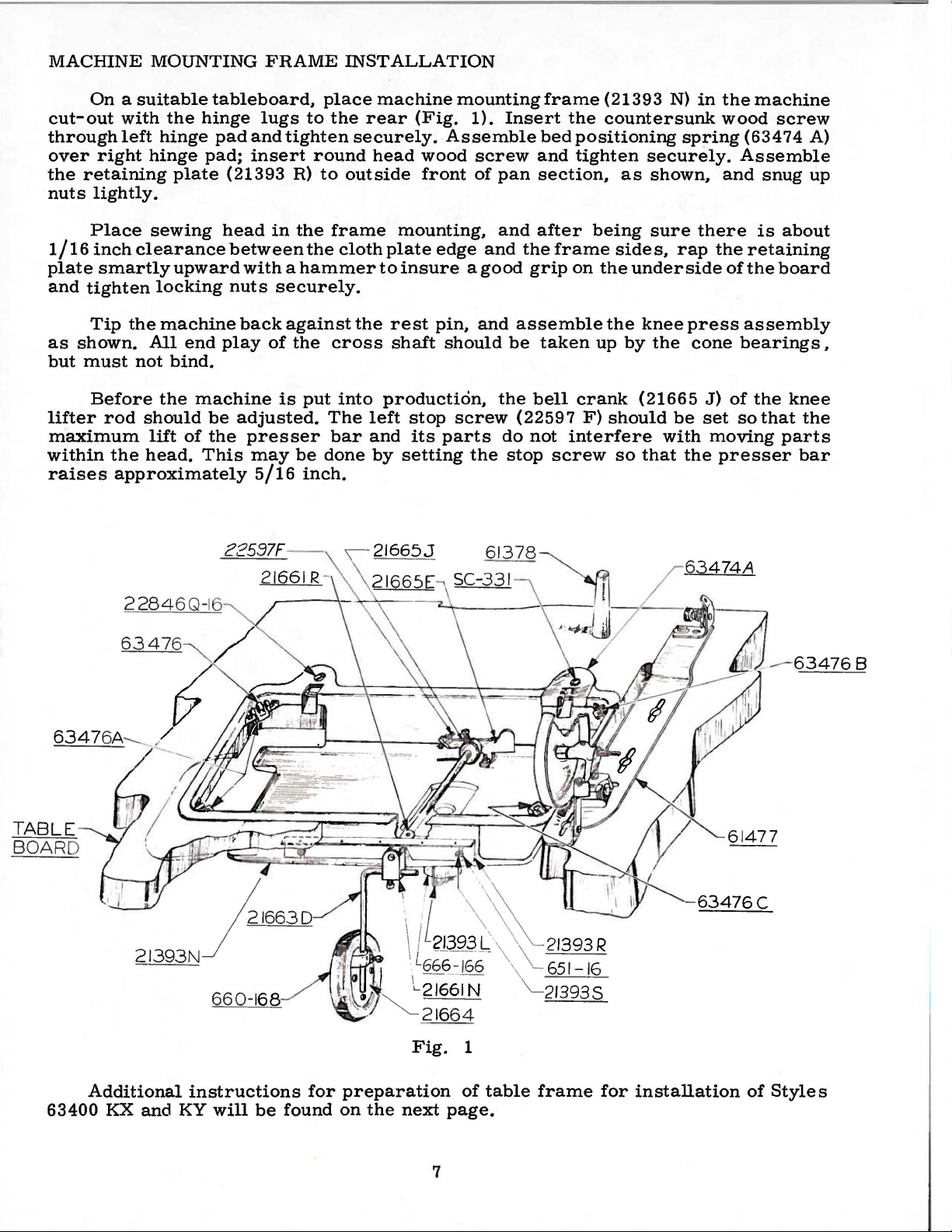
MOUNTING
FRAME
INSTALLATION
On a suitable
cut-out
through
over
the
nuts
with
left
right
retaining
lightly.
Place
1/16
inch
plate
and
smartly
tighten
Tip
as
shown.
but
must
Before
lifter
rod
maximum
within
raises
the
approximately
the
hinge
hinge
plate
sewing
clearance
upward
locking
the
machine
All
end
not
bind.
the
should
lift
of
head.
tableboard,
hinge
pad;
pad
lugs
and
insert
(21393
head
between
with a hammer
nuts
back
play
machine
be
adjusted.
the
presser
This
may
5/16
place
to
tighten
round
R)
to
in
the
the
securely.
against
of
the
is
put
The
be
done
inch.
the
rear
securely.
head
outside
frame
cloth
the
cross
into
left
bar
and
by
machine
mounting
(Fig.
Assemble
wood
front
mounting,
plate
to
edge
insure a good
rest
pin,
shaft
should
production,
stop
screw
its
parts
setting
1).
screw
of
pan
and
and
and
the
do
the
frame
Insert
bed
and
section,
after
the
frame
grip
assemble
be
taken
bell
(22597
not
stop
screw
(21393
the
countersunk
positioning
tighten
as
being
sides,
on
the
underside
the
knee
up
by
crank
F)
(21665
should
interfere
so
that
N)
in
spring
securely.
shown,
sure
there
rap
press
the
cone
J)
be
set
with
moving
the
the
machine
wood
(63474
Assemble
and
snug
is
the
retaining
of
the
assembly
bearings,
of
the
so
that
presser
screw
A)
up
about
board
knee
the
parts
bar
TABLE
BOARD
2284
6347
6Q-16
6
Fig.
1
-
63476C
Additional
63400
KX
and
instructions
KY
will
be
for
found
preparation
on
the
next
page.
7
of
table
frame
for
installation
of
Styles
CLAMP
From the library of: Superior Sewing Machine & Supply LLC
'-~-i
00
-
5YNCHR
ON
IZER
*c;;3"1-~5'D
6RAC.I<Er
*Jsu
SC
REW
2_
FRO
M TENSION-
J RELEASE
)_
FROM CUTTIN
J
SOLENOI
.SOLENO
D
*sc-a
92
SC
REW
}~~--:rl,
~=
't::,i.C-:t:J
ID
G.
-tr
,
..
(APPROX.)-----1
SCRcW.S
= = =
=::__
==
, ,
( DIA. DR
(BRACKET
EE
DETAIL
S
*
"SYNCHRONI
)
...
ILL
ZE.~
NU
TS
TO
SECUR£
BOX
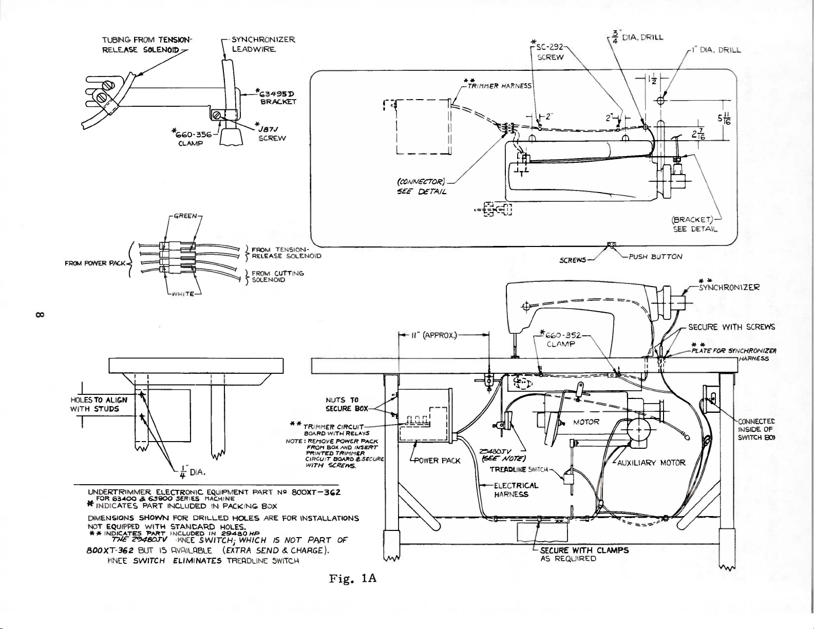
UNDE
RTR
IMMER ELECTR
F
OR
63-400
IONS
ICATES
TilE
KN
362
EE
&.
ES
SHOWN
~BDIII
BUT
SWITCH
* INDICAT
DIMENS
NOT EQUIPPED WI
**IND
BOOXT-
1
if
63900
PA
SERIES MACHI
RT
INCLU
FOR DRIL
TH
STANCARD HOLES.
'PART INC
IS 0.
L..U0£0
·KN£
\IP.
ELIM
••
DIA.
ONI
C. EQUIPM
DED
E
SWITCHj
ILABLE (EXTRA
INATES
IN
PACKING.
LED
IN
29480
ENT
NE
HOLES ARE
WHICH
TREADU
PART
HP
5£ND
NE 5WI
NCI
S OX
IS
**TRIMM
NO
TE:
800XT-3~2
FOR
NOT
&.
CHARGE).
TC.I-I
£~
CI
BOARO WI
REMO
FROM
PRIIV
CIRCU IT
W
ITH
INSTALLATIONS
PART
RCU
TH
RELA
VE POWE.R PACI<
BOlt
AND
T~O
TR
IMH
BOARD
SCR£11$.
OF
Fig.
IT I I"=":
YS
I
NS~T
£R
(£SE
CURE
lA
aJ.IN
ECTEt
l
t-I
SIDE OF
SWITCH
80>
1.
From the library of: Superior Sewing Machine & Supply LLC
2.
3.
4.
5.
6.
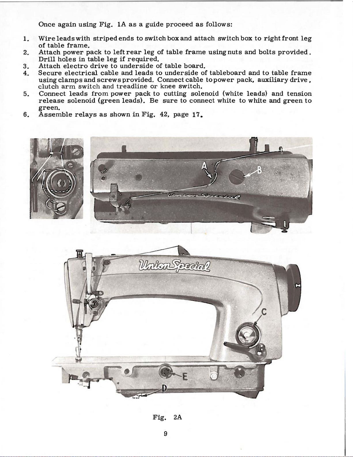
Once
Wire
of
Attach
Drill
Attach
Secure
using
clutch
Connect
release
green.
Assemble
again
leads
table
power
holes
electro
electrical
clamps
arm
using
with
frame.
pack
in
table
drive
and
switch
leads
solenoid
relays
Fig.
striped
to
leg
cable
screws
and
from
(green
as
1A
ends
left
rear
if
to
underside
and
provided.
treadline
power
leads).
shown
as a guide
to
switch
leg
required.
of
leads
pack
in
to
or
to
Be
Fig.
proceed
box
of
table
table
underside
Connect
knee
42,
switch.
cutting
sure
page
and
frame
board.
cable
solenoid
to
connect
17.
as
follows:
attach
using
of
tableboard
to
switch
nuts
power
(white
white
box
and
and
pack,
leads)
to
white
to
right
bolts
to
table
auxiliary
and
and
front
provided.
green
leg
frame
drive,
tension
to
Fig.
2A
9
The
From the library of: Superior Sewing Machine & Supply LLC
located
when
in
allow
The
pulley
against
is
described
Catalog
bobbin
directly
operation.
the
mechanism
of
the
belt
No.
winder
in
the
to
under
121 M.
should
front
The
to
of
base
be
winder,
wind
the
"Winding
be
the
sewing
of
the
moved
when
bobbin.
the
BOBBIN
secured
machine
winder
closer
in
operation,
Regulation
Bobbin",
BELTS
WINDER
to
the
belt
has
two
to
or
farther
should
and
under
table
top
and
so
will
elongated
away
exert
operation
OPERATOR'S
that
its
pulley
bear
attaching
from
only
of
against
belt
enough
the
holes,
bobbin
INSTRUCTIONS
will
the
as
needed.
pressure
winder
be
belt
which
in
These
Thread
thread
thru
Then
hole,
right
frame
no
thru
ing
passes
the
middle
it
passes
thru
to
left.
thread
threading
the
next
at
check
right.
CAUTION!
the
reservoir
Fillmain
Oil
is
at
maximum
to
the
right
is
to
the
black
stainless
at
1000Fahrenheit
fication
water-white
No.
machines
machine
thru
hole
thru
the
middle
Machine
eyelet
thru
the
frame
spring
Oil
must
reservoir
of
''OPERATE"
line,
in
175.
are 'equipped
Styles
the
frame
from
the
left
next
hole
Styles
(A)
from
middle
thread
has
has
be
eyelet
been
been
filled
atplug
safe
operating
zone,
located
straight
the
main
to
use
either# 1 "Vee"
THREADING
63400 X and Y as
thread
to
frame
from
63400
left
hole.
enlarged
right
left
to
On
only
eyelet
and
thread
to
right
KX
and
right
Styles
thru
for
then
and
the
OILING
drained
before
screw
to
the
mineral
reservoir.
from
starting
(B,
level
when
marked
left
oil
Fig.
't.FULL.
of
''OPERATE"
of a Saybolt
This
indicated
(A)
thru
thru
eyelet
and
KY
are
thru
63400
upper
clarity.
the
main
to
operate.
2A)
the
needle
is
in
the
rear
the
front
from
right
finally
threaded
the
front
KX
and
hole
from
Needle
reservoir
and
check
is
Oil
should
zone,
viscosity
equivalent
or
Fig.
thru
KY
is
to
to
round
2A,
hole
hole
to
left
the
thru
hole
the
thread
right
threaded
before
oil
level
the
black
be
added
marked
of
90
Union
belts.
noting
from
from
thru
lower
the
from
to
to
Special
right
right
the
hole
rear
right
then
left.
Thread-
from
shipment
at
gau
line,
when
"LOW".
125
seconds
that
the
to
left,
to
left.
upper
from
hole
to
left,
passes
left
and
ge
(C).
located
needle
Use
speci-
of
to
a
Oil
may
be
The
dial
in
the
clockwise
It
is
long
parts.
Run
speed
period,
After
machine
operation
The
as
for
Styles
following
covered
that
catalog.
drained
quantity
of
direction
direction
recommended
be
lubricated
oiling,
slowly
can
adjusting
63400 A
exceptions
in
Catalog
from
oil
supplied
of
the
decreases
main
arrow
the
that a new
by
removing
replace
for
then
head
several
be
expected
INSTRUCTIONS
instructions
for
and B respectively,
and
additions.
No. 121 M;
the
reservoir
to
the
hook
by
is
(counterclockwise)
oil
flow.
machine,
cover
minutes
without
Styles
or
one
the
head
as
no
further
to
distribute
damage.
FOR
MECHANICS
63400 X and
covered
The
instructions
headings
will
removing
controlled
that
cover
indicate
10
plug
increases
has
and
hand
oil
to
KX,
in
Catalog
that
are
the
screw
by
dial
been
oiling
oiling
the
Y
and
No.
different
page
(E).
the
oil
out
of
all
will
various
KY
121 M,
it
can
(D,
Fig.
Turning
flow
service
the
be
required.
parts.
are
from
be
and
for
moving
the
same
with
the
found
2A).
the
in
Full
the
ones
in
a
a
 Loading...