


Union Special 81300A, 81300A1, 81300A1H, 81300A2, 81300AJ Parts List
...INSTRUCTIONS AND ILLUSTRATED PARTS MANUAL INSTRUCCIONES Y CATALOGO DE PARTES Y PIEZAS
ANTAEUS Y HERAKLES COMBINADA, MAQUINA DE DOS AGUJAS, CUATRO HILOS, PUNTADA DE SEGURIDAD, PARA COSER SIN PELIGRO DE DESPLAZAMIENTO PIEZAS DE SACOS DE MATERIAL PESADO / FUERTE
MANUAL NO. / CATALOGO Nº G230A
FOR STYLES / PARA ESTILOS
81300A, AJ, A1, A1H, A2 - 81300B, B1H, B2
MANUAL NO. G230A
INSTRUCTIONS AND ILLUSTRATED PARTS LIST
FOR 81300 SERIES MACHINES
Third Edition Copyright 2002
by
Union Special GmbH Rights Reserved in All
Countries
Printed in Germany
PREFACE
This catalog has been prepared to guide you while operating 81300 series machines and arranged to simplify ordering spare parts.
This catalog explains in detail the proper settings for operation of the machines. Illustrations are used to show the adjustments and reference letters are used to point out specific items discussed.
Careful attention to the instructions and cautions for operating and adjusting these machines will enable you to maintain the superior performance and reliability designed and built into every Union Special bag sewing machine.
Adjustments and cautions are presented in sequence so that a logical progression is accomplished. Some adjustments performed out of sequence may have an adverse effect on the function of the other related parts.
This manual has been comprised on the basis of available information. Changes in design and / or improvements may incorporate a slight modification of configuration in illustrations or cautions.
On the following pages will be found illustrations and terminology used in describing the instructions and the parts for your machine.
In addition to the instructions and to the mandatory rules and regulations for accident prevention and environmental protection in the country and place of use of the machine / unit, the generally recognized technical rules for safe and proper working must also be observed.
The instructions are to be supplemented by the respective national rules and regulations for accident prevention and environmental protection.
CATALOGO NO. G230A
INSTRUCCIONES Y LISTA DE PARTES
ILUSTRADAS MODELOS SERIE 81300
Tercera Edición © 2002
Union Special GmbH
Derechos Reservados
en todos los paises del mundo Impreso en Alemania
INTRODUCCION
Este manual fue preparado para guiar al usuario en la operación de máquinas de la serie 81300 y ayudar a simplificar la elaboración de los pedidos de repuestos.
Este manual explica detalladamente los ajustes para la operación de la máquina. Las ilustraciones sirven para demostrar los ajustes y las letras en referencia indican los puntos específicos discutidos.
Una cuidadosa atención a las instrucciones y las precauciones operando y ajustando estas máquinas le va a permitir mantener el mejor funcionamiento y la confiabilidad que caracteriza las máquinas cosedoras de sacos de Union Special.
Los ajustes y precauciones son presentados en secuencia para que se consiga una progresión lógica. La ejecución de algunos ajustes fuera de la secuencia puede causar un efecto adverso para el funcionamiento de otras partes relacionadas.
Este manual se comprende a base de la información actual. Cambios en diseño y/o mejoras pueden significar leves modificaciones de la configuración de las ilustraciones o precauciones.
En las paginas siguientes se encuentran ilustraciones y terminologías usadas en la descripción de las instrucciones y las piezas de la máquina.
Adicionalmente a las instrucciones, las reglas y regulaciones obligatorias para prevenir accidentes y la protección ambiental del país y lugar donde se encuentra la máquina/unidad, hay que considerar las reglas técnicas para un trabajo seguro y adecuado.
Las instrucciones hay que complementarlas con las respectivas reglas y regulaciones nacionales contra accidentes y protección del ambiente.
2

TABLE OF CONTENTS
INDICE
SAFETY RULES
REGLAS DE SEGURIDAD
IDENTIFICATION OF MACHINES
IDENTIFICACION DE LAS MAQUINAS
APPLICATION OF THIS INSTRUCTION MANUAL
APLICACION DE ESTE MANUAL DE INSTRUCCIONES
ORDERING WEAR AND SPARE PARTS
INSTRUCCIONES PARA LOS PEDIDOS DE REPUESTOS
STYLES OF MACHINES
ESTILOS DE MAQUINAS
INSTALLATION
INSTALACION
LUBRICATING
LUBRICACION
NEEDLES
AGUJAS
THREADING DIAGRAM
DIAGRAMA DE ENHEBRADO
OPERATING INSTRUCTIONS
INSTRUCCIONES DE OPERACION
MAINTENANCE
MANTENIMIENTO
INSTRUCTIONS FOR MECHANICS
INSTRUCCIONES PARA LOS MECANICOS
VIEWS AND DESCRIPTION OF PARTS
DIBUJOS Y DESCRIPCION DE LOS REPUESTOS
BUSHINGS, SIGHT FEED OILER, SPRING VALVE OILER
BOCINAS Y PARTES DE LUBRICACION
CLOTH PLATE, BASE PLATE, GUARDS AND MISCELLANEOUS COVERS
TAPA Y BASE DE LA MAQUINA, GUARDAS Y OTRAS TAPAS
THREAD TENSIONS AND THREAD GUIDE PARTS
TENSIONES DE LOS HILOS Y PARTES DE LOS GUIA HILOS
NEEDLE BAR, NEEDLE LEVER, CRANK SHAFT, HANDWHEEL
BARRAS DE LA AGUJA, LEVANTADOR DE AGUJA, EJE PRINCIPAL, VOLANTE
LOOPER DRIVE MECHANISM
MECANISMO DE OPERACION DEL LOOPER
LOWER AND UPPER FEED DRIVE MECHANISM
MECANISMOS DEL TRANSPORTE INFERIOR Y SUPERIOR
PRESSER BARS, LEAF SPRINGS AND PRESSER FOOT LIFTER LEVER FOR 81300A, AJ, A1, B
BARRAS, MUELLES PARA LAS BARRAS Y LEVANTADOR DEL PIE PRENSATELAS PARA 81300A, AJ, A1, B
ELECTRO-PNEUMATIC PARTS KIT FOR UPPER FEED PRESSURE AND LIFTER FOR 81300A1H, A2, B1H, B2 PIEZAS SISTEMA ELECTRONEUMATICO PARA PRESION DEL PIE SUPERIOR Y LEVANTAR PIE PRENSATELAS PARA 81300A1H, A2, B1H, B2
CONTROL FOR ELECTRO-PNEUMATIC HOT THREAD CHAIN CUTTER FOR 81300A1H, B1H
CONTROL SISTEMA ELECTRONEUMATICO CORTADOR CALIENTE DE CADENETA PARA 81300A1H, B1H
ELECTRO-PNEUMATIC HOT THREAD CHAIN CUTTER FOR 81300A1H, B1H
SISTEMA ELECTRONEUMATICO CORTADOR CALIENTE DE CADENETA PARA 81300A1H, B1H
SEWING PARTS - PIEZAS DE FORMACION DE COSTURA
ACCESSORIES - ACCESORIOS
NUMERICAL INDEX OF PARTS - INDICE NUMERICO DE PARTES
Page
Página
4 - 5
6
6
6
7
8 - 9
10 - 11
11
12
13
13
14-22
23
24 - 25
26 - 27
28 - 29
30 - 31
32 - 35
36 - 37
38 - 39
40 - 41
42 - 45
46 - 47
48 - 49
50 -51
52 - 53
3

SAFETY RULES
1.Before putting the machines described in this manual into service, carefully read the instructions. The starting of each machine is only permitted after taking notice of the instructions and by qualified operators.
IMPORTANT! Before putting the machine into service, also read the safety rules and instructions from the motor supplier.
2.Observe the national safety rules valid for your country.
3.The sewing machines described in this instruction manual are prohibited from being put into service until it has been ascertained that the sewing units which these sewing machines will be built into, have conformed with the provisions of EC Machinery Directive 98/37/EC, Annex II B.
Each machine is only allowed to be used as foreseen. The foreseen use of the particular machine is described in paragraph "STYLES OF MACHINES" of this instruction manual. Another use, going beyond the description, is not as foreseen.
4.All safety devices must be in position when the machine is ready for work or in operation. Operation of the machine without the appertaining safety devices is prohibited.
5.Wear safety glasses.
6.In case of machine conversions and changes all valid safety rules must be considered. Conversions and changes are made at your own risk.
7.The warning hints in the instructions are marked with one of these two symbols.
8.When doing the following the machine has to be disconnected from the power supply by turning off the main switch or by pulling out the main plug.
8.1When threading needle(s), looper, spreader etc.
8.2When replacing any parts such as needle, presser foot, throat plate, looper, spreader, feed dog, needle guard, folder, fabric guide etc.
8.3When leaving the workplace and when the work place is unattended.
8.4When doing maintenance work.
8.5When using clutch motors with or without
actuation lock, wait until motor is stopped totally.
REGLAS DE SEGURIDAD
1.Antes de poner en marcha las máquinas descritas en este manual, hay que leer cuidadosamente las instrucciones. El arranque de cada máquina solamente se permite después de haber leído las instrucciones y por personal calificado.
IMPORTANTE! Antes de poner la máquina a operar, también hay que leer las reglas de seguridad y las instrucciones del fabricante del motor.
2.Observe las reglas nacionales de seguridad que rigen para su país.
3.No se puede poner en marcha la máquina descrita en este manual hasta que se confirme que la unidad de coser esta conforme con el reglamento del Directivo de las Máquinas de la Comunidad Europea 98/37/EC, Anexo II B.
La máquina solamente se puede utilizar para su uso previsto. El uso previsto esta descrito en el capitulo ESTILO DE MAQUINAS de este manual de instrucciones. Otro uso, diferente de la descripción, no está previsto.
4.Todos los dispositivos de seguridad tienen que estar en su sitio cuando la máquina esté lista para trabajar u operando. La operación de la máquina sin los dispositivos de seguridad esta prohibida.
5.Utilice lentes de seguridad.
6.En el caso de una modificación de la máquina hay que tomar en cuenta las reglas de seguridad. Modificaciones y cambios corren por su riesgo.
7.Las advertencias en el manual de instrucciones están marcadas con las siguientes señales de aviso:
8.Para las siguientes maniobras hay que desconectar la máquina del suministro eléctrico desconectando el enchufe principal:
8.1Enhebrando agujas, loopers y spreaders.
8.2 |
Reemplazando piezas como agujas, pie prensa |
|
tela, plancha de aguja, looper, spreader, dientes |
|
de arrastre, guarda aguja, dobladilladores, guía |
|
tela, cuchillas, etc. |
8.3Cuando salga de su puesto de trabajo y no se
encuentre alguien para atender la máquina.
8.4Durante trabajos de mantenimiento.
8.5Utilizando motores de embrague sin freno, tiene que esperar que el motor pare completamente.
4
9.Maintenance, repair and conversion work (see item 8) must be done only by trained technicians orspecial skilled personnel under condsideration of the instructions.
Only genuine spare parts approved by UNION SPECIAL have to be used for repairs. These parts are designed specifically for your machine and manufactured with utmost precision to assure long lasting service.
10.Any work on the electrical equipment must be done by an electrician or under direction and supervision of special skilled personnel.
11.Work on parts and equipment under electrical power is not permitted. Permissible exceptions are described in the applicable section of standard sheet EN 50 110 / VDE 0105.
12.Before doing maintenance and repair work on the pneumatic equipment, the machine has to be disconnected from the compressed air supply. In case of existing residual air pressure after disconnecting from compressed air supply (e.g. pneumatic equipment with air tank), the pressure has to be removed by bleeding. Exceptions are only allowed for adjusting work and function checks done by special skilled personnel.
9.Mantenimiento, reparaciones y trabajos de conversión (véase No. 8) solamente pueden ser efectuados por técnicos entrenados o personal especializado bajo consideración de las instrucciones.
Solamente repuestos originales y aprobados por Union Special pueden ser utilizados para reparaciones. Estos repuestos han sido diseñados específicamente para estas máquinas, con precisión y para asegurar su máxima vida útil.
10.Cualquier trabajo con el equipo eléctrico tiene que ser ejecutado por un electricista o bajo la supervisión de personal especialmente entrenado.
11.No está permitido trabajar en piezas y equipos con la electricidad conectada. Excepciones permitidas están descritas en EN 50110 / VDE 0105.
12.Antes de hacer mantenimiento o reparaciones del equipo neumático, hay que desconectar la máquina de la alimentación del aire comprimido. En el caso que exista una presión de aire residual después de desconectar la máquina (por ejemplo equipos con tanques de aire), la presión tiene que ser eliminada abriendo las válvulas. Excepciones están solamente permitidas para trabajos de ajuste y revisión de funciones por personal especialmente entrenado.
5

IDENTIFICATION OF MACHINES |
IDENTIFICACION DE LAS MAQUINAS |
Each UNION SPECIAL 81300 series machine is identified by a style number, which is stamped on the style plate affixed to the right front of machine. Serial number is stamped into bed casting at the right front base of machine.
APPLICATION OF THIS INSTRUCTION MANUAL
NOTE: Instructions stating direction or location, such as right, left, front or rear of machine, are given relative to operator’s position at the machine, unless otherwise noted.
The handwheel pulley rotates clockwise, in operating direction. when viewed from the right end of machine.
CAUTION! Before putting into service check the direction of rotation. Breakage may occur when the direction of rotation is wrong.
ORDERING WEAR AND SPARE PARTS
To simplify ordering wear and spare parts exploded views of various sections of the mechanism are shown, so that the parts may be seen in their actual position in the machine. On the page opposite the illustration will be found a listing of the parts with their part numbers, descriptions and the number of pieces required in the particular view being shown.
Numbers in the first column are reference numbers only, and merely indicate the position of that part in the illustration. Reference numbers should never be used in ordering parts. Always use the part number listed in the second column.
Component parts of sub-assemblies which can be furnished for repairs are indicated by identing their description under the description of the main subassembly.
At the back of the catalog will be found a numerical index of all parts shown in this catalog. This will faciliate locating the illustration and description when only the part number is known.
IMPORTANT! ON ALL ORDERS, PLEASE INCLUDE PART NUMBER, PART NAME, QUANTITY REQUIRED AND STYLE OF MACHINE FOR WHICH PART IS ORDERED.
Cada máquina UNION SPECIAL 81300 está identificada por un número de estilo, el cual está estampado en la placa fijada a la máquina. El número de serial está troquelado en la carcasa de la máquina.
APLICACION DE ESTE MANUAL DE INSTRUCCIONES
NOTA: Instrucciones que se refieren a direcciones y posiciones como derecho, izquierdo, adelante o atrás se entienden desde el punto de vista de un operador sentado enfrente de la máquina, si no está notificado de una manera diferente.
El manubrio del volante gira en sentido del reloj, en su dirección de operación, cuando es visto desde la parte derecha del final de la máquina.
PRECAUCION: Revise antes de poner la máquina en marcha el sentido de la rotación. El sentido de rotación equivocado puede causar roturas.
PEDIDO DE PIEZAS DE REPUESTOS
Este catálogo fue diseñado para facilitar los pedidos de los repuestos. Los dibujos de grupos específicos del mecanismo demuestran la posición de las piezas en la máquina de coser. En la página en frente de la página de la ilustración se encuentra un listado de las piezas con su número de repuesto, descripción y la cantidad requerida para la sección indicada.
Los números de la primera columna son números de referencia e indican donde se encuentra la piezas en la ilustración. Los números de referencia no se deben utilizar en sus pedidos de repuestos. Utilice siempre el número de repuesto de la segunda columna.
Componentes de piezas compuestas que se pueden suministrar como repuestos se encuentran diferenciados en tal forma que las descripciones están desplazadas hacia la derecha referente a la descripción de la pieza compuesta.
Al final de este catálogo se encuentra un listado de los números de partes de todos los repuestos que están descritos en el mismo. Esto facilita encontrar la ilustración y descripción de la pieza en el caso que solamente se conozca el número del repuesto.
NOTA! FAVOR INDICAR EN TODOS LOS PEDIDOS EL NUMERO, LA DESCRIPCION DEL REPUESTO Y EL MODELO DE LA MAQUINA.
6
STYLES OF MACHINES
81300A: Combined ANTAEUS / HERAKLES two needle four thread safety stitch machine. Lower and upper feed. Adjusted for polypropylene sewing threads.
Manual lubrication.
For matched seaming of very heavy bag fabrics made of jute, burlap or woven polypropylene with a 10 mm (3/8") wide overedge stitch on the fabric edge and in a distance of 5 mm (13 gauge) to this with an additional double locked stitch.
Seam specification (401.502) SSa-2. Needle distance 5 mm (13 gauge). Seam width over all 15 mm (19/32"). Standard needle 9853GA430/172.
Stitch range 6 to 13 mm ( 2 to 4 SPI), standard setting 10 mm (2 1/2").
Working dia. of handwheel pulley 150 mm (5 29/32"). Capacity below the presser foot up to 19 mm (3/4"). Speed up to 1400 stitches per minute depending on the operation.
Recommended operating speed 1200 stitches per minute. Equivalent continuous A-weighted sound pressure level on work stations at recommended operating speed: 84 dB(A) according to DIN 45635-48 / ISO 10 821.
Weight net: 40 kg
81300AJ: Same as 81300A, but adjusted for jute threads.
81300A1: Same as 81300A, but with feed dog A10482A and throat plate A10481AC with opening 6 mm for filler cord from below and guide for filler cord from the top for sealing the needle punctures of the left needle.
81300A1H: Same as 81300A, but with built-in electropneumatically operated hot thread chain cutter. Electropneumatically operated presser foot and upper feed dog lifter.
Pneumatic presser foot spring.
Guides for filler cord from the top and / or from below for sealing the needle punctures of the left needle.
81300A2: Same as 81300A1H, but without any thread chain cutter.
81300B: Same as 81300A, but oberedge seam width 19 mm = seam width overall 24 mm.
81300B1H: Same as 81300A1H, but overedge seam width 19 mm = seam width overall 24 mm.
81300B2: Same as 81300A1H, but overedge seam width 19 mm = seam width overall 24 mm and without any thread chain cutter.
Use UNION SPECIAL sewing tables for the described sewing machines. UNION SPECIAL sewing tables complete the particular sewing machine to a sewing unit and guarantee safe operation as well as the indicated data of the sound pressure level generated by the sewing unit.
ESTILOS DE MAQUINAS
81300A: Combinación de ANTAEUS / HERAKLES, máquina de dos agujas, cuatro hilos, puntada de seguridad. Alimentación superior e inferior. Especial para trabajos con hilos de polipropileno. Lubricación manual.
Para coser sin peligro de desplazamiento los pliegos de los sacos contenedores de material muy pesado, como yute, arpillera o polipropileno tejido con una puntada de 10 mm de ancho y en una distancia de 5 mm, con puntada doble de seguridad.
Especificación de costura (401.502) SSa-2. Distancia entre agujas 5 mm.
Ancho máximo de costura 15 mm. Aguja normal 9853GA430/172.
Rango de puntada 6 - 13 mm, ajuste normal 10 mm. Diámetro efectivo del volante 150 mm.
Capacidad debajo del pie prensatelas hasta 19 mm. Velocidad hasta 1400 puntadas / min., dependiendo de la operación.
Velocidad de operación recomendada 1200 puntadas / min. Nivel de ruido de la unidad referente a al puesto de trabajo con la velocidad de operación recomendada: 84 dB(A) de acuerdo con normas DIN 45635-48 / ISO 10 821.
Peso neto: 40 kg.
81300AJ: Igual a la 81300A, pero ajustada para hilos de yute.
81300A1: Igual a la 81300A, pero con transporte A10482A y plancha de aguja A10481AC con apertura de 6 mm para cordón de relleno que viene desde abajo y guía para cordón de relleno que viene desde arriba para sellar las perforaciones de la aguja izquierda.
81300A1H: Igual a la 81300A, pero con cortador electroneumático caliente de cadeneta y pie prensatelas y levantador del diente superior activados electroneumáticamente.
Pie prensatelas con presión neumática por pistón.
La máquina esta equipada con una guía superior e inferior de los cordeles para sellar las perforaciones de las agujas desde arriba y/o desde abajo de la aguja izquierda.
81300A2: Igual a la 81300A1H, pero sin cortador caliente de cadeneta.
81300B: Igual a la 81300A, pero con ancho de costura de 19 mm = ancho de costura total 24 mm.
81300B1H: Igual a la 81300A1H, pero con ancho de costura de 19 mm = ancho de costura total 24 mm.
81300B2: Igual a la 81300A1H, pero con ancho de costura de 19 mm = ancho de costura total 24 mm y sin ningún cortador de cadeneta.
Utilice montajes de UNION SPECIAL para las máquinas descritas. Mesas y pedestales de UNION SPECIAL complementan las máquinas de coser a una unidad de coser y garantizan una operación segura y los niveles de ruido.
7
8

INSTALLATION (continued)
1.Unpack the sewing machine and the accessories.
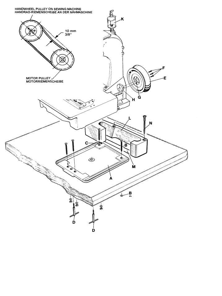
2.Mount the base plate (A) with four screws, nuts and washers (B) in the provided holes on the table board.
3.Place the sewing machine on the base plate so that the roll pin (C) in the base plate engages with the right rear hole in the machine base.
4.Fasten the sewing machine with the two T-screws
(D)on the base plate.
5.Place the V-belt, supplied with the sewing table, on the handwheel pulley .
6.Assemble the handwheel pulley (E) with three countersunk screws (F) to the sewing machine. Pin
(G)must engage with the hole in hub (H).
7.Screw in needle bar guard (J).
8.Screw in sight feed oiler (K).
9.Align the handwheel belt guard (L) with the V-belt slot (M) in the table board and with the handwheel pulley and fasten it with two wood screws (N) on the table board.
10.Dismount motor belt guard. Place the V-belt around the motor pulley and slue the motor to tense the belt. The tension on the V-belt is correct, when with moderate finger pressure it will deflect approx.10 mm (3/8") midway between handwheel pulley on the sewing machine and motor pulley.
Remount motor belt guard.
11.Hook the lifter chain to the lifter lever of the sewing machine and to the small treadle on the sewing table.
12.Assemble the thread stand and mount the thread stand base with four wood screws on the right rear corner of the table board.
13.Before being put into service note the specified service voltage and frequency of the motor. Check if the mains voltage and frequency at site correspond with the factory specified service voltage and frequency.
14.Check the direction of rotation. The handwheel pulley must rotate clockwise (to the right), when viewed from the right end of the machine.
Switch on the motor. Only shortly and very slightly depress the motor treadle and check the direction of rotation. Immediately release the treadle. Switch off and wait until the motor has stopped.
CAUTION! In case the direction of rotation has to be changed, the reversing of the polarity is only allowed to be done by a skilled electrician.
INSTALACION (Continuación)
1.Desempaque la máquina y los accesorios.
2.Monte la placa de base (A, Fig. 1) con los 4 tornillos, las tuercas y las arandelas (B) en los huecos ya listos en la tabla de la mesa.
3.Coloque la máquina sobre la base, de manera que el pasador de regulación (C) en la placa base, encaje en el hueco derecho trasero de la base de la máquina.
4.Asegure la máquina de coser con los 2 tornillos T (D) en la placa de base.
5.Coloque la correa en forma de V, en la rueda del volante.
6.Monte el volante (E) con los 3 tornillos remache (F) a la máquina de coser. El pasador (G) debe encajar en el hueco de la parte central del volante (H).
7.Atornille el protector de la barra de aguja (J).
8.Apriete la aceitera (K).
9.Alinee el guarda correa del volante (L) con la perforación para la correa en la mesa (M) y con la rueda del volante y sujételo con los 2 tornillos para madera (N) a la mesa.
10.Desmonte el guarda correa del motor. Coloque la correa en V alrededor del volante y ajuste el motor para tensar la correa. La tensión del la correa en V será la correcta cuando ejerciendo presión moderada con el dedo ceda en aprox. 10mm (3/8 pulgada) en la mitad entre la rueda del volante en la máquina de coser y la rueda del motor (Ver Fig. 2).
Coloque nuevamente el guarda correa del motor.
11.Enganche la cadena a la palanca levantadora de la máquina de coser y al pequeño pedal en la mesa de la máquina de coser.
12.Asegure la base del porta conos con tres tornillos al lado derecho de la mesa de la máquina de coser y monte el porta conos.
13.Antes de comenzar a utilizar la máquina, verifique que el voltaje y la frecuencia del motor coinciden con la instalada en el lugar donde operará la máquina.
14.Verifique la dirección de rotación. El volante debe girar en dirección del reloj (a la derecha), cuando es visto desde la parte derecha de la máquina.
Encienda el motor. Presione ligeramente el pedal y chequee la dirección de rotación. Suéltelo inmediatamente. Apague el motor y espere hasta que se detenga totalmente.
PRECAUCION! En el caso que la dirección de rotación deba ser cambiada, la reversión de la polaridad debe ser realizada por un electricista calificado.
9

LUBRICATING
CAUTION! Turn off main power switch before lubricating! When using clutch motors with or without actuation lock wait until motor has completely stopped.
LUBRICACION
PRECAUCION! Antes de lubricar, apague el interruptor principal. Con un motor de embrague sin freno espere hasta que el motor se detenga completamente!
Fig. 1
10
LUBRICATING (continued)
PREPARING FOR OPERATION
Before operating a new machine for the first time, the sight feed oiler has to be adjusted. All lubricating points, indicated on the oiling diagram (Fig. 1) have to be oiled. For adjusting fill the sight feed oiler halfway with oil and turn the metering pin (A, Fig. 1) a little bit out and then turn it in, until there will flow two to three drops of oil per minute. This can be checked on the sight glass (B). Secure the setting of the metering pin with lock nut (C). Fill the oiler.
Repeat the oiling of a new machine after 10 minutes of operation!
When the machine is out of operation, the oil flow can be stopped by tilting lever (D) on the sight feed oiler.
IMPORTANT!The oil flow has to be switched on again before operating the machine.
For lubrication we recommend "Mobil Oil DTE Medium" or equivalent, which can be purchased from UNION SPECIAL in 1/2 liter containers under part number G28604L or in 5 liter containers under part number G28604L5.
NEEDLES
Each needle has both a type and a size number. The type number denotes the kind of shank, point, length, groove, finish and other details. The metric size number, stamped on the needle shank, denotes largest diameter of blade, measured in hundreds of a mm midway between shank and eye. Collectively, the type and size number represent the complete symbol, which is given on the label of all needles packaged and sold by UNION SPECIAL.
TYPE AND DESCRIPTION
9853GA Round shank with tapered flat, rounded square point, single groove, spotted, chromium plated.
Sizes available: 300/120, 400/156, 430/172.
Standard needle for these machines is 9853GA430/172.
When changing the needle, make sure it is fully inserted in the needle head with the fastening flat of the needle shank facing the screw, before the screw is tightened.
NEEDLE ORDERING
When ordering needles please use the complete type and size numbers as printed on the package to ensure prompt and accurate processing of your order.
A complete order should read as follows: 100 needles, type 9853GA430/172.
LUBRICACION (Continuación)
INSTRUCCIONES DE OPERACION
Antes de poner en marcha una nueva máquina por la primera vez, hay que fijar y ajustar el engrasador cuentagotas. Lubrique todos los puntos indicados en el diagrama de lubricación (Fig. 1). Llene el engrasador cuentagotas hasta la mitad con aceite y ajuste girando el pasador de la regulación (A, Fig. 1) en tal manera que suministre aproximadamente dos gotas de aceite por minuto. Este ajuste se puede revisar a través del vidrio (B). Asegure la posición del pasador de la regulación con la contratuerca (C). Llene el engrasador cuentagotas con aceite.
Para máquinas nuevas, repita la lubricación después de diez minutos de operación.
Si la máquina no está operando se puede parar el flujo del aceite doblando la palanca (D) del engrasador cuentagotas.
Nota: El flujo de aceite tiene que ser restablecido antes de operar la máquina otra vez.
Para la lubricación recomendamos „Mobil Oil DTE Medium“ o un aceite equivalente, que se puede pedir a UNION SPECIAL en contenedores de ½ litro bajo el número de referencia G28604L y en contenedores de 5 litros bajo el número de referencia G28604L5.
AGUJAS
Cada aguja tiene un número de sistema y un número del grosor. El número del sistema se refiere al tipo del cabo, la punta, el largo, la ranura, acabado y otros detalles. El número del grosor, troquelado en el cabo, indica el grosor máximo de la caña, medido en la mitad de la distancia entre cabo y ojo de la aguja. El número del sistema y del grosor dan la descripción completa, que se encuentra en todos los empaques de agujas vendidas por UNION SPECIAL.
TIPO Y DESCRIPCION
9853GA Cabo redondo con superficie plana para asentar la aguja, punta cuadrada redondeada, ranura simple, rebajo, cromada. Tamaños disponibles: 300/120, 430/172.
Aguja normal para estas máquinas es 9853GA430/172.
Al cambiar la aguja, asegúrese que esté totalmente insertada en su lugar, con la superficie plana para asentar la aguja frente al tornillo, antes de apretarlo.
PEDIDO DE AGUJAS
Para garantizar un despacho correcto y rápido les sugerimos enviarnos el empaque vacío de las agujas o una aguja de muestra o indicar el sistema con el grosor. Utilice la descripción de la etiqueta en el empaque de la aguja.
Un pedido completo de agujas sería por ejemplo: 100 agujas, tipo 9853GA, Grosor 430/172.
11

THREADING DIAGRAM
CAUTION! Turn off main power switch before threading! When using clutch motors with or without actuation lock wait until the motor has completely stopped!
DIAGRAMA DE ENHEBRADO
PRECAUCION! Apague el motor principal antes de enhebrar!. Cuando utilice motor con clutch debe esperar hasta que el mismo se detenga totalmente!.
Aguja izquierda |
Aguja derecha |
Fig. 2
12

OPERATING INSTRUCTIONS
THREADING
81300 series are threaded as shown in Fig. 2.
For threading the needle turn handwheel in operating direction until the needle is in the upmost position.
For looper threading open the hinge plate by lifting locking bolt knob (A, Fig. 2).
Reclose hinge plate after threading.
OPERATING
1.Switch on main power switch.
2.Without lifting the presser foot, place the fabric to be sewn as close as possible in front of the needle and to the right on the edge guide.
CAUTION! Remove the foot from the motor treadle, to avoid inadvertently starting of the machine, in case it is necessary to lift presser foot and upper feed dog for aligning the fabric to be sewn!
3.Depress the motor treadle. The machine sews. Guide the fabric to be sewn.
INSTRUCCIONES DE OPERACION
ENHEBRADO
Las máquinas de la serie 81300 se enhebran como se muestra en la Fig. 2.
Para enhebrar la aguja gire el volante en dirección de operación hasta que la aguja alcance su posición mas alta. Para enhebrar el looper, abra la tapa delantera levantando el tornillo de la manivela (A, Fig. 2).
Cierre la tapa delantera otra vez.
OPERACION
1.Active el interruptor principal.
2.Ponga las telas lo más cercano posible delante de la aguja y a la derecha a la guía tope, sin levantar el pie prensatela.
PRECAUCION!! Quite el pie del pedal del motor para no arrancar la máquina accidentalmente, si fuera necesario levante el pie prensatela y el transporte superior manualmente para guiar las telas.
3.Pise el pedal de motor hacia adelante. La máquina cose. Guíe las telas.
CAUTION! Keep a security distance of approx. 100 mm (4") between hand and sewing needle when guiding the fabric to be sewn!
PRECAUCION! Mantenga una distancia de por lo menos 100 mm entre la aguja y la mano mientras guíe las telas!
4.Release the motor treadle. The machine stops.
Cut the thread chain at the trailing edge of the fabric and remove the fabric from the machine.
MAINTENANCE
CAUTION! Turn off main power switch before doing maintenance works! When using clutch motors with or without actuation lock wait until the motor has stopped!
4.Suelte el pedal del motor. La máquina se parará. Corte la cadeneta al final de las telas cosidas y quite los sobrantes de la superficie de la máquina.
MANTENIMIENTO
PRECAUCION! Antes de efectuar cualquier trabajo de mantenimiento, apague el interruptor principal de la máquina. Con un motor de embrague sin freno, espere hasta que el motor se detenga completamente!
LUBRICATING AND CLEANING
The machines of class 81300 have to be cleaned and lubricated twice a day before the morning and afternoon start on the lubrication points indicated on the oiling diagram (Fig. 1, page 10). The sight feed oiler has to be kept filled and should be ajdusted so, that it feeds two to three drops of oil per minute. The oiler has to be refilled latest, when 2/3 of the oil are used up (see also page 11).
LUBRICACION Y LIMPIEZA
Las máquinas de la serie 81300 hay que limpiar dos veces al día – preferiblemente en la mañana y en la tarde antes de empezar la operación - y lubricar con aceite en los puntos indicados en el diagrama de lubricación (Fig. 1, pág. 10). Llene el engrasador cuentagotas hasta la mitad con aceite y ajuste girando el pasador de la regulación en tal manera que suministre aproximadamente dos gotas de aceite por minuto. Hay que rellenar el engrasador cuentagotas con aceite cuando se hayan consumido 2/3 de su contenido. (Ver también pág. 11)
13
INDSTRUCTIONS FOR MECHANICS
HINT: The right needle forms along with the left lower looper at the rear, the right upper spreader with thread hook and the thread retainer the overedge stitch type 502 (HERAKLES). The left needle forms along with the left lower looper at the front and the upper cross looper the double locked stitch type 401 (ANTAEUS).
INSERTING THE NEEDLES
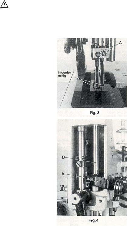
Before adjusting the machine insert a new set of needles with the shank as far as possible into theneedleholder.Thelonggroove of the needles must point to the front (towards the operator). Tighten the set screws (A, Fig. 3) on the tapered fastening flats of the needle shanks.
ALIGNING THE NEEDLE BAR
Remove the face cover and the finger guard left on the machine head as well as the upper feed dog and the presser foot. Rotate handwheel in operating direction and check if the needles center in the associated needle holes of the throat plate (see Fig. 3). If not loosen clamp screw (A, Fig. 4) in the needle bar connection and turn the needle bar (B) accordingly. Retighten screw (A.). HINT: For aligning the needle bar test plate No. 040 37006 0000 can be used in lieu of the throat plate. The test plate is an extra order and charge item.
SETTINGTHELOWERLOOPER FOR THE OVEREDGE STITCH
Remove the cloth plate with hinge plate and throat plate, the feed dog, the throat plate support and the needle guard. Insert the lower looper (A, Fig. 5) into the rear hole of the looper lever (B). Now snug the set screw (C) at the back of the looper lever against the flat on the looper shank (E) so that the lower looper point passes as close as possible to the spot on the back of the right needle (R), without deflecting it. Now tighten the second screw (D) firmly.
INSTRUCCIONES PARA MECANICOS
DATO: La aguja derecha, junto con el looper inferior izquierdo en la parte posterior, el spreader superior con el gancho retenedor del hilo y el retenedor de hilo, forma la costura tipo 502 (HERAKLES). La aguja izquierda, junto con el looper izquierdo inferior en la parte frontal y el cruce del looper superior forma la costura doble de seguridad tipo 401 (ANTAEUS).
INSERTAR LA AGUJA
Antes de ajustar la máquina inserte un nuevo juego de agujas, en tal manera que el cabo de la aguja toque el final de la barra de aguja y la ranura de la aguja esté posicionada hacia adelante (en dirección al operador). Apriete los tornillos (A, Fig. 3) en la superficie plana para asentar la aguja.
AJUSTE DE LA BARRA DE AGUJA
Remueva la cubierta frontal y el guarda dedos en la carcasa de la máquina, así como también el alimentador superior y el pie prensatelas. Gire el volante en dirección de operación y verifique que la aguja cuadre en el hueco para la aguja en la plancha de aguja. (Ver Fig. 3). Si no, suelte el tornillo sujetador (A, Fig. 4) en la barra de conexión de la aguja y gire la barra de aguja (B) como sea necesario. Apriete el tornillo (A).
DATO: Para alinear la barra de aguja, la plancha para test No. 040 37006 0000 puede ser utilizada en vez de la plancha de agua. Esta plancha tiene un costo adicional y es una orden extra.
AJUSTE DEL LOOPER SUPERIOR PARA LA PUNTADA MAS ANCHA
Quite la plancha de tela, la plancha articulada y la plancha de aguja, el alimentador, el soporte de la plancha de aguja y el guarda agujas. Inserte el looper inferior (A, Fig. 5) en el hueco posterior de la palanca del looper (B). Acomode el tornillo de sujeción (C) detrás de la palanca del looper contra la parte plana del tronco del looper (E) de manera tal que el que la punta inferior del looper pase lo mas cerca posible del punto en la parte posterior de la aguja derecha (R) pero sin tocarla. Apriete el segundo tornillo (D) firmemente.
SETTING HEIGHT OF NEEDLE BAR
Rotate handwheel in operating direction until the point of lower looper (A, Fig. 5) projects 3 mm (1/8") to the right
from the right side of the right needle. Lower edge of looper and upper edge of needle eye must be flush in this position. If an adjustment is necessary loosen clamp screw (A, Fig. 4) in the needle bar connection and move the needle bar
(B) up or down, as required. Care should be taken not to disturb the alignment of the needle bar when making this adjustment. Retighten clamp screw.
AJUSTE DE LA ALTURA DE LA BARRA DE AGUJA
Gire el volante en dirección de operación hasta que la punta del looper inferior (A, Fig. 5) sobresalga 3 mm. a la derecha del lado derecho de la aguja. En esta posición, el borde del looper y el borde superior del ojo de la aguja deben estar nivelados. De ser necesario algún ajuste adicional, suelte el tornillo sujetador (A, Fig. 4) en la conexión de la barra de aguja y mueva la barra de aguja (B) hacia arriba o hacia abajo, como sea necesario. Tenga mucho cuidado de no descuadrar la alineación de la barra de aguja mientras efectúe este ajuste. Apriete de nuevo el tornillo sujetador.
14

SETTING THE RIGHT UPPER SPREADER FOR THE OVEREDGE STITCH
AJUSTE DEL SPREADER SUPERIOR PARA LA PUNTADA MAS ANCHA
Before inserting a new spreader (F, Fig. 6) remove thread hook (J). This facilitates the visual check of the adjustment.
For adjustment of spreader (F, Figs. 6 and 7) with respect to the needles (L and R), the shank of spreader (F) has two offset flats.
Proceed as follows:
First snug one screw (M, Fig. 6) on the flat of the spreader shank which obtains the following position of the spreader: When rotating the handwheel in operating direction spreader (F, Fig. 7) should pass with the tip of its upper prong (H) in a distance of 0.25 to 0.3 mm (.010 to .012") behind the left needle (L) and its face (K) should not contact the front of the right needle (R). Now tighten the second screw (M, Fig. 6).
HINT: In case the adjusting possibility of the spreader by means of the two offset flats on the spreader shank is not sufficient, additionally the complete spreader shaft bearing (S, Fig. 8) can be moved slightly up or down when loosening screws (R). Retighten screws.
In the extreme left upper end position of spreader (F, Fig. 6), the bottom of the cutout between the two looper prongs (G and H) should be flush with the left side of the left needle (L).
If an adjustment is necessary, loosen nuts (N and P, Fig. 8) and turn connecting rod (Q) forward or backward as required to obtain the required position.
NOTE: The left nut (P) has a left hand thread. Temporarily snug the two nuts (N and P) manually.
Remount thread hook (J, Fig. 6) on spreader (F).
Rotate handwheel in operating direction until the spreader is in its extreme right lower end position. The spreader should not contact any machine parts during its motion. If required loosen clamp screw (U, Fig. 10) in the spreader drive lever (V) and set the lever so that the spreader (F) clears at all points. Retighten clamp screw.
After this setting recheck the position of the spreader to the left needle, as described above. Reset with connecting rod (Q, Fig. 8) if required and tighten nuts (N and P).
Antes de colocar el nuevo spreader (F, Fig. 6) retire el gancho retenedor del hilo (J). Esto permite visualizar mejor el ajuste.
Para ajustar el spreader superior (F, Figs. 6 y 7) con respecto a las agujas (L y R) el cuello del spreader (F) tiene dos superficies planas.
Proceda de la siguiente manera:
Primero acomode un tornillo (M, Fig. 6) contra la parte plana del cuello del spreader, con lo cual se alcanzará la siguiente posición del spreader: Cuando se gire el volante en dirección de costura, el spreader (F, Fig. 7) debe pasar con la punta de su tenaza (H) a una distancia de 0.25 a 0.3 mm por detrás de la aguja izquierda (L) y su cara (K) no debe tocar el frente de la aguja derecha (R). Apriete el segundo tornillo (M, Fig. 6).
DATO: En el caso de que de haber hecho el ajuste del spreader a ambos lados del tronco no sea suficiente, se recomienda mover el rodamiento del looper (S, Fig. 8) ligeramente hacia arriba o hacia abajo, cuando se suelten los tornillos (R). Apriete los tornillos.
En la extrema posición superior izquierda del spreader (F, Fig. 6) la parte inferior del corte entre las tenazas del looper (G y H) debe estar al nivel del lado derecho de la aguja izquierda (L).
De ser necesario un ajuste, afloje las tuercas (N y P, Fig. 8) y gire la varilla de conexión (Q) hacia adelante o hacia atrás, como sea requerido, hasta obtener la posición adecuada.
NOTA: La tuerca izquierda (P) enrosca a la izquierda. Temporalmente ajuste las dos tuercas (N y P)
manualmente.
Monte de nuevo el gancho retenedor del hilo (J, Fig.6) en el spreader (F).
Gire el volante en dirección de operación hasta que el spreader superior esté en su posición extrema inferior. El spreader no debe tocar ninguna parte de la máquina durante esta operación. Si es necesario, afloje el tornillo de sujeción (U, Fig. 10) en la palanca (V) y ajústela de manera tal que el spreader superior (F) no toque ninguna de estas piezas. Apriete el tornillo de sujeción.
Después de realizar este ajuste, verifique la posición del spreader superior con la aguja, tal y como se describe en el párrafo anterior. Reajuste con la barra de conexión (Q, Fig. 8) de ser necesario y apriete de nuevo las tuercas (N y P) .
15

SETTING THE RIGHT UPPER SPREADER FOR THE
OVEREDGE STITCH (continued)
Rotate handwheel in operating direction. On the upward travel of spreader (F, Fig. 9) the tip of its lower prong (G) must pass as close as possible in the recess behind the eye of the lower looper (A) without contacting it.
If an adjustment is required, loosen nut (T, Fig. 8) on the double joint and swing the lower looper lever with lower looper accordingly to the right or left. Retighten nut (T).
NOTE: |
Check the setting of the needle bar height |
|
after making this adjustment and reset if |
|
required. Refer to paragraph "SETTING |
|
HEIGHT OF NEEDLE BAR". |
SETTING THE THREAD RETAINER FOR THE OVEREDGE STITCH
AJUSTE DEL SPREADER SUPERIOR PARA LA PUNTADA
MAS ANCHA (Continuación)
Gire el volante en dirección de operación. En la extrema superior del recorrido del spreader (F, Fig. 9) la punta inferior de su tenaza (G) debería pasar lo mas cerca posible del espacio detrás del ojo del looper inferior (A) pero sin tocarlo.
De ser necesario un ajuste, suelte la tuerca (T, Fig. 8 ) en la doble unión y mueva la palanca del looper inferior con el looper inferior hacia la derecha o izquierda, como sea necesario. Reajuste la tuerca (T).
NOTA: Revise la altura de la barra de aguja después de realizar estos ajustes y reajuste de ser necesario. Refiérase al párrafo "AJUSTE DE LA ALTURA DE LA BARRA DE AGUJA."
AJUSTE DEL RETENEDOR DE HILO PARA LA PUNTADA MAS ANCHA
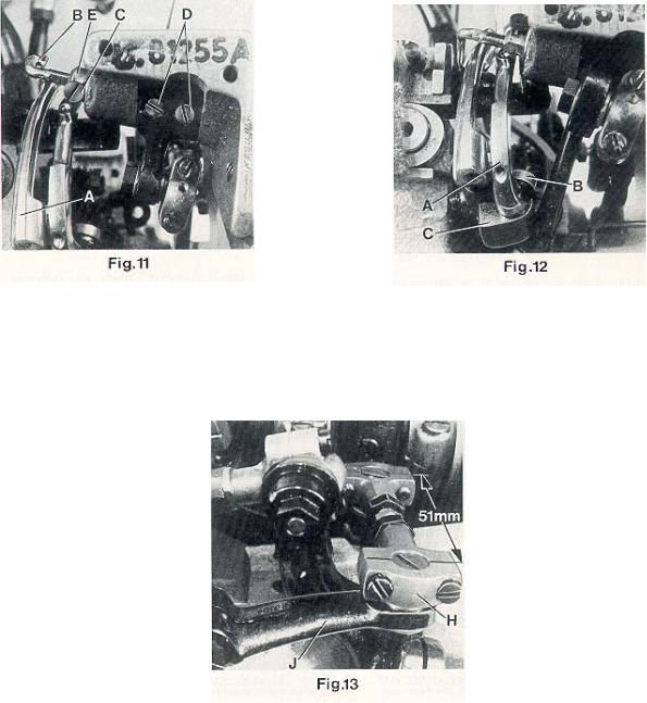
Viewed from the left end of the machine the thread retainer (B, Fig. 11) should pass as close as possible on the left side of lower looper (A) when swinging upward without contacting it.
On the most upward position of its swing motion the thread retainer (B) should not interfere neither with the bottom of the throat plate nor with the feed dog.
Visto desde la extrema izquierda del final de la máquina, el retenedor de hilo (B, Fig. 11) debe pasar tan cerca como sea posible del lado izquierdo del looper inferior (A) en su movimiento hacia arriba, pero sin tocarlo.
En su posición más alta en este movimiento, el retenedor de hilo
(B) no debe tocar ni la plancha de aguja ni el alimentador.
16
SETTING THE THREAD RETAINER FOR THE OVEREDGE STITCH (continued)
After loosening screw (C, Fig. 11) the thread retainer (B) can be moved to the left or right. Retighten screw on the flat of the thread retainer shank.
After loosening the two set screws (D), shaft (E) with the thread retainer (B) can be rotated into the correct position. Make sure to remove all lateral end play when tightening the set screws.
SETTING THE DOUBLE LOCKED STITCH LOOPER
Insert the double locked stitch looper (A, Fig. 12) and tighten it with screw (B) on the flat of its shank so that it passes as close as possible behind the left needle without touching it. Now tighten set screw (C).
SETTING THE CROSS LOOPER FOR DOUBLE LOCKED STITCH
The distance (set at the factory) from center to center of the two ball joints driving the cross looper should be 51 mm (2") (see Fig. 13).
Basically the front ball joint (H, Fig. 13) should be positioned as far as it will go to the left in the fastening slot of the cross looper drive lever (J).
When rotating the handwheel in operating direction cross looper (D, Fig. 14) should swing as close as possible in the recess behind the eye over the double locked stitch looper (A) without contacting it.
At the left end of its swing motion cross looper (D, Fig. 15) must be positioned so that the left needle
(L) securely stitches into the thread loop hanging around the hook of cross looper (D). In front of the left needle the cross looper should pass in a distance of 0.3 mm (.012") (see Fig. 15).
Check this as follows:
Hang a piece of thread around the hook of the cross looper and draw it slightly in sewing direction. Now rotate handwheel in sewing direction. The left needle must enter securely between the two thread ends.
AJUSTE DEL RETENEDOR DE HILO PARA LA PUNTADA MAS ANCHA (Continuación)
Después de soltar el tornillo (C, Fig. 11) el retenedor de hilo (B) puede moverse hacia la izquierda o derecha. Apriete el tornillo en la parte plana del cuello del retenedor de hilo.
Después de soltar los tornillos de sujeción (D), el cuello (E) con el retenedor de hilo (B) debe moverse hasta lograr la posición correcta. Asegúrese de corregir cualquier movimiento fuera de sitio antes de apretar los tornillos.
AJUSTE DEL LOOPER PARA DOBLE PUNTADA DE SEGURIDAD
Inserte el looper para doble puntada de seguridad (A, Fig. 12) y asegúrelo con los tornillos (B) en la parte plana de su cuello, de manera que pase tan cerca como sea posible por detrás de la aguja izquierda pero sin tocarla. Apriete el tornillo (C).
AJUSTE DEL LOOPER CRUZADO PARA DOBLE PUNTADA DE SEGURIDAD
La distancia (de fábrica) del centro de las dos articulaciones esféricas que manejan el looper cruzado debe ser de 51 mm (Ver Fig. 13).
La articulación esférica frontal (H, Fig. 13) debe quedar lo más lejos posible a la izquierda de la ranura de seguridad de la palanca del looper cruzado (J).
Girando el volante en dirección de operación el looper cruzado (D, Fig. 14) debe moverse los más cerca posible del espacio detrás del ojo del looper para doble puntada de seguridad (A) pero sin tocarlo.
Al final izquierdo de su recorrido, el looper cruzado (D, Fig. 15) debe estar posicionado de manera tal que la aguja izquierda (L) forme la puntada en el lazo del hilo guindando alrededor de el gancho retenedor del hilo del looper cruzado (D). El looper cruzado debe pasar frente a la aguja izquierda a una distancia de 3 mm (Ver Fig. 15).
Verifique lo siguiente:
Pase un hilo alrededor de el gancho retenedor del hilo del looper cruzado y hálelo ligeramente en dirección de costura. Ahora gire el volante en direccion de operación. La aguja izquierda debe entrar tranquilamente entre los dos hilos.
17
 Loading...