


Union Special FS322312, FS322C01, FS322H01, FS332C01, FS332E12 Parts List
...ILLUSTRATEDPARTSMANUAL
FS300SERIES,PLAINANDDIFFERENTIALFEED,
HIGH SPEED FLAT BED MACHINES
MANUAL NO. PT9800
FORSTYLES
FS322C01 FS335E42
FS332C01 FS322H01
FS322E12 FS332H01
FS332E12 FS322L01
FS335E41 FS332L21
USE IN CONJUNCTION WITH MACHINE SERIAL NUMBER PREFIX (BG) AND LATER
REV 5-9-00

Manual No. PT9800 llustrated Parts List for FS300 Series Machines
First Edition Copyright 2000
By
Union Special Corporation Rights Reserved In All Countries
Printed in U.S.A. May 2000
PREFACE
This parts manual has been prepared to assist you in locating individual parts or assemblies on FS300 Series machines. It can be used in conjunction with Union Special Operator's Manual OP9614 and Engineer's Manual EN9424.
It is the desire of Union Special that each machine run at its optimum performance. Parts listed in this manual are designed specifically for your machine and are manufactured with utmost precision to assure long lasting service.
This manual has been comprised on the basis of available information. Changes in design and/or improvements may incorporate a slight modification of configuration in illustrations or part numbers.
On the following pages are illustrations and terminology used in describing the parts used on FS300 Series machines.
Please include part number, name and style of machine for which the part was ordered.
For optimum performance use only genuine Union Special replacement parts.
2

CONTENTS |
|
PREFACE ....................................................................................................................................................................................... |
2 |
IDENTIFICATIONOFMACHINES .................................................................................................................................................. |
4 |
STYLEOFMACHINES .................................................................................................................................................................... |
4 |
ILLUSTRATIONS ............................................................................................................................................................................. |
5 |
IDENTIFYINGPARTS ...................................................................................................................................................................... |
5 |
NEEDLES ........................................................................................................................................................................................ |
5 |
SAFETYRULES ............................................................................................................................................................................... |
6 |
BUSHINGS ..................................................................................................................................................................................... |
9 |
NEEDLEBAR ............................................................................................................................................................................... |
11 |
UPPERMAINSHAFT .................................................................................................................................................................... |
13 |
SPREADER ................................................................................................................................................................................... |
15 |
THREADGUIDE ........................................................................................................................................................................... |
17 |
TENSIONRELEASE&THREADTENSION ..................................................................................................................................... |
19 |
PRESSERFOOTLIFT ..................................................................................................................................................................... |
21 |
COVERS,UPPER ARM ............................................................................................................................................................... |
23 |
LOWERMAINSHAFT .................................................................................................................................................................. |
25 |
LUBRICATION, OIL TUBING & OIL PUMP ................................................................................................................................... |
27 |
LOOPERDRIVE ........................................................................................................................................................................... |
29 |
NEEDLEGUARD ......................................................................................................................................................................... |
31 |
LOOPERTHREADTAKE-UP ......................................................................................................................................................... |
33 |
FEEDDRIVEMECHANISM |
|
FOR FS322C01,FS332CO1,FS322H01,FS332H01,FS332L01,FS332L21 .................................................... |
35 |
FEEDDRIVEMECHANISM |
|
FORFS322E12&FS332E12 ........................................................................................................................... |
37 |
FEEDDRIVEMECHANISM .......................................................................................................................................................... |
39 |
COVERS,LOWERBED ................................................................................................................................................................ |
41 |
COVERS,LOWERBED ................................................................................................................................................................ |
43 |
FRONTCOVERASSEMBLY |
|
FOR FS322C01, FS332C01 ........................................................................................................................... |
45 |
SEWINGPARTS |
|
FOR FS322C01 & FS332C01 ......................................................................................................................... |
47 |
SEWINGPARTS |
|
FOR FS322E12&FS332E12 .......................................................................................................................... |
51 |
SEWINGPARTS |
|
FORFS335E41&FS335E42 ........................................................................................................................... |
53 |
SEWINGPARTS |
|
FORFS322H01,FS332H01,FS332L01,FS332L21 ........................................................................................... |
57 |
TABLINGANDNEEDLEDIPPER ASSEMBLY(EXTRASENDCHARGE) |
|
FORFS322C01,FS332CO1,FS335E41,FS335E42,FS322H01,FS332H01,FS332L01,FS332L21 ................. |
59 |
TABLING(EXTRASENDCHARGE) |
|
FORFS322E12&FS332E12 ........................................................................................................................... |
61 |
ACCESSORIES ............................................................................................................................................................................ |
63 |
VACUUMTUBEASSEMBLYANDPNEUMATICCONTROL(EXTRASENDCHARGE) |
|
FORFS322E12&FS332E12 ........................................................................................................................... |
65 |
UNDERBEDTHREADTRIMMER |
|
FORFS322E12&FS332E12 ........................................................................................................................... |
67 |
LOWERROLLERASSEMBLY |
|
FORFS335E41&FS335E42 ........................................................................................................................... |
69 |
UPPERROLLERASSEMBLY |
|
FORFS335E41&FS335E42 ........................................................................................................................... |
71 |
PULLERLIFTERASSEMBLY |
|
FORFS335E41&FS335E42 ........................................................................................................................... |
73 |
PULLERDRIVEASSEMBLY |
|
FORFS335E41&FS335E42 ........................................................................................................................... |
75 |
NUMERICALINDEXOFPARTS ................................................................................................................................................... |
76 |
NUMERICALINDEXOFPARTS ................................................................................................................................................... |
77 |
NUMERICALINDEXOFPARTS ................................................................................................................................................... |
78 |
NUMERICALINDEXOFPARTS ................................................................................................................................................... |
79 |
3

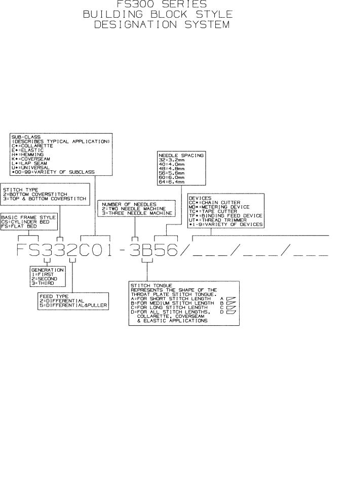
IDENTIFICATION OF MACHINES
Each UNION SPECIAL machine is identified by a style number, which is stamped into the style plate affixed to the middle of the machine under the tension assembly. The serial number is stamped into the serial number plate affixed to the right rear base of the machine.
STYLE OF MACHINES
FS322C01COLLARETTE - Two or three needle, bottom coverstitch. Typical application - For attaching flat of ribbed knit split tube borders to knit garments. Seam specification fir two needle 406BSb-1, three needle 407BSb-1. Standard gauges for two needle 32, (1/8", 3.2mm), 40, (5/32", 4.0mm), 48, (3/16", 4.8mm), for three needle 48, (3/16", 4.8mm), 56, (7/32" 5.6mm), 64, (1/4", 6.4mm). Maximum recommended speed, depending on application is up to 6500 R.P.M.
FS332C01COLLARETTE - Same as style FS322C01 except top and bottom coverstitch. Seam specification for two needle 602BSb-1, for three needle 605BSb-1.
FS322E12ELASTIC - Two or three needle, bottom coverstitch with fabric trimmer. Typical application - For attaching elastic to briefs or lace to lingerie. Seam specification for two needle 406LSa-1, for three needle 407LSa-1. Standard gauges for two needle 32,
(1/8", 3.2mm), 40, (5/32", 4.0mm), 48, (3/16", 4.8mm), for three needle 48, (3/16", 4.8mm), 56, (7/32", 5.6mm), 64, (1/4", 6.4mm). Maximum recommended speed, depending on application is up to 6500 R.P.M.
FS332E12- |
ELASTIC |
- |
Same as Style FS322E12 except top and bottom coverstitch with fabric trimmer. |
||||
|
Seam specification for two needle 602LSa-1, for three needle 605LSa-1. |
|
|||||
FS335E41- |
ELASTIC |
- |
Three needle, top and bottom coverstitch, differential feed and rear puller with |
||||
|
tooth roller. Typical application - for attaching tunnel elastic to briefs or lace to lingerie. |
||||||
|
Seam specification 605EFg-1. Standard gauges 56, (7/32", 5.6mm), 64, (1/4", 6.4mm). |
||||||
|
Maximum recommended speed, depending on application is up to 6000 R.P.M. |
||||||
FS335E42- |
ELASTIC |
- |
Same as style FS335E41 except puller with smooth roller. |
|
|||
FS322H01- |
HEMMING |
- |
Two of three needle, bottom coverstitch. Typical application - for hemming |
||||
|
on light to medium weight knit fabrics. Seam specifications for two needle 406EFa-1 (inv.), |
||||||
|
for three needle 407EFa-1 (inv.). Standard gauge for two needle 40, (5/32" 4.0mm), 48, |
||||||
|
(3/16", 4.8mm), for three needle 48, (3/16", 4.8mm), 56, (7/32", 5.6mm), 64, (1/4", 6.4mm). |
||||||
|
Maximum recommended speed, depending on application is up to 6500 R.P.M. |
||||||
FS332H01- |
HEMMING |
- |
Same as style FS322H01 except top and bottom coverstitch. |
Seam |
|||
|
specification for two needle 602EFa-1 (inv.), for three needle 605EFa-1 (inv.). |
||||||
FS332L01- |
LAP SEAMING |
|
- Two or three needle, top and bottom coverstitch, tandem differential |
||||
|
feed. Typical application - for general seaming on fleece and knit garments. Seam |
||||||
|
specification for two needle 602LSa-1, for three needle 605LSa-1. Standard gauges for |
||||||
|
two needle 32, (1/8", 3.2mm), 40, (5/32", 4.0mm), for three needle 48, (3/16" 4.8mm), |
||||||
|
56, (7/32", |
5.6mm), 64, (1/4", 6.4mm). |
Maximum recommended speed, |
depending on |
|||
|
application is up to 6500 R.P.M. |
|
|
||||
FS332L21- |
LAP SEAMING |
- |
Same as style FS332L01 except three needle, off set differential feeds. |
||||
|
Standard |
gauges |
56, (7/32", 5.6mm), 64, |
(1/4"6.4mm). |
|
||
4

ILLUSTRATIONS
This manual has been arranged to simplify ordering repair parts. Exploded views of various sections of the mechanism are shown so that the parts may be seen in their actual position in the machine. On the page opposite the illustration will be found a listing of the parts with their part numbers, description and the number of pieces required in the particular view being shown.
Numbers in the first column are reference numbers only, and merely indicate the position of the part in the illustration. The reference number should never be used in ordering parts. Always use the part number listed in the second column.
Component parts of sub-assemblies which can be furnished for repairs are indicated by indenting their |
|||
descriptions under the description of the main sub-assembly. |
As an example refer to the following text. |
||
5. |
50366B |
Needle Thread Strike-Off Assembly ............................................................................... |
1 |
6. |
50358V |
Needle Thread Strike-Off .................................................................................. |
1 |
7. |
50370F |
Thread Strike-Off Component .......................................................................... |
1 |
8. |
SS7060310SP |
Screw, for plate strike-off .................................................................................. |
1 |
When a part is common to all machines covered in this manual, no specific usage will be mentioned in the description. However, when the parts for the various machines are not the same, the specific usage will be mentioned in the description and, if necessary, the difference will be shown in the illustration.
*Ref. No. showing no Part No. is for location only. Part is not for sale separately.
A numerical index of all the parts shown in this manual is located at the back. This will facilitate locating the illustration and description when only a part number is known.
IDENTIFYING PARTS
Where construction permits, each part is stamped with its part number. On some of the smaller parts and on those where construction does not permit, an identification letter is stamped in to distinguish the part from similar ones.
PLEASENOTE: |
Part numbers represent the same part, regardless of which manual they appear. On all |
|
orders |
|
NEEDLES |
Each needle has both a type and size number. The type number denotes the kind of shank, point, length, groove, finish and other details. The size number, stamped on the needle shank, denotes the largest diameter of the blade measured between the shank and the eye. Collectively, the type number and size number represent the complete symbol which is given on the label of all needles packed and sold by Union Special.
TYPE |
|
|
DESCRIPTION |
|
128GBS |
Short, |
double |
groove, struck groove, ball |
eye, spotted, ball point, chromium plated- |
|
Sizes |
available |
065/025, 070/027, 075/029, |
080/032, 090/036. |
When changing the needle, make sure it is fully inserted in the needle holder before the screw is tightened.
When ordering needles, please use the complete type and size numbers as printed on the package to ensure prompt and accurate processing of your order. A complete order should read as follows: "100 needles, type 128 GBS, size 075/029".
5

SAFETYRULES
1.Before putting the machines described in this manual into service, carefully read the instructions. The starting of each machine is only permitted after taking notice of the instructions and by qualified operators.
IMPORTANT! Before putting the machine into service, also read the safety rules and instructions from the motor supplier.
2. Observe the national safety rules valid for your country.
3. The sewing machines described in this instruction manual are prohibited from being put into service until it has been ascertained that the sewing units which these sewing machines will be built into, have conformed with the EC Council Directives (89/392/EEC, Annex II B).
Each machine is only allowed to be used as foreseen. The foreseen use of the particular machine is described in paragraph “STYLES OF MACHINES” of this instruction manual. Another use, going beyond the description, is not as foreseen.
4. |
All |
safety devices |
must |
be in position when the |
machine |
is |
ready |
for work |
or in operation. Operation |
||||
|
o f |
the |
machine without |
the appertaining |
safety |
devices |
is |
prohibited. |
|
||||
5. |
Wear |
safety |
glasses. |
|
|
|
|
|
|
|
|
||
6. |
In case of machine conversions and |
changes all |
valid safety rules |
must be |
considered. Conversions |
||||||||
|
a n d changes |
are |
made |
at your own |
risk. |
|
|
|
|
|
|
||
7. |
The warning |
hints |
in the |
instructions |
are |
marked |
with one |
of |
these |
two symbols: |
|||
8. When doing the following the machine has to be disconnected from the power supply by turning off the main switch or by pulling out the main plug:
8.1When threading needle(s), looper, spreader etc.
8.2When replacing any parts such as needle(s), presser foot, throat plate, looper, spreader, feed dog, needle guard, folder, fabric guide etc.
8.3When leaving the workplace and when the workplace is unattended.
8.4When doing maintenance work.
8.5 When using clutch motors without actuation lock, wait until the motor is stopped totally.
9.Maintenance, repair and conversion work (see item 8) must be done only by trained technicians or special skilled personnel under consideration of the instructions.
10. Any work |
on the electrical equipment must be done by an electrician or under direction and supervision |
of special |
skilled personnel. |
11.Work on parts and equipment under electrical power is not permitted. Permissible exceptions are described in the applicable sections of standard sheet DIN VDE 0105.
12.Before doing maintenance and repair work on the pneumatic equipment, the machine has to be disconnected from the compressed air supply. In case of existing residual air pressure, after disconnecting from compressed air supply (i.e. pneumatic equipment with air tank), the pressure has to be removed by bleeding.
6
7
8

|
|
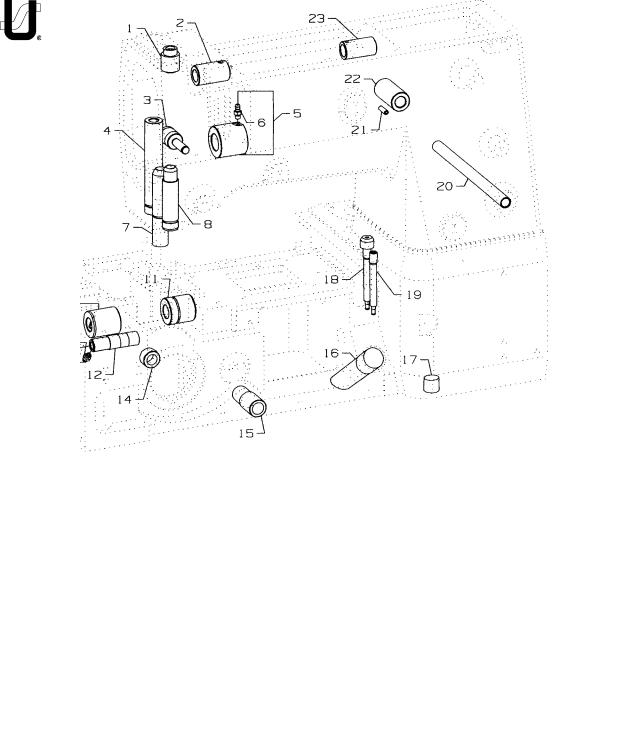
BUSHINGS |
|
Ref. |
|
|
Amt . |
No.. |
Part No. |
Description |
Req. |
1. |
50354J |
Bushing, for needle bar, upper .................................................................... |
1 |
2. |
50347F |
Bushing, for spreader, front ......................................................................... |
1 |
3. |
50332U |
Pin, for front lifter lever ................................................................................. |
1 |
4. |
50347L |
Bushing, for spreader drive ......................................................................... |
1 |
5. |
50344BU |
Bushing, front .............................................................................................. |
1 |
6. |
SQ1110401MZ |
Fitting .................................................................................................... |
1 |
7. |
50330CZ |
Bushing, for presser bar ............................................................................... |
1 |
8. |
50354H |
Bushing, for needle bar, lower ..................................................................... |
1 |
9. |
50344BE |
Bushing, for lower mainshaft, left ................................................................ |
1 |
10. |
SQ1110401MZ |
Fitting .................................................................................................... |
1 |
11. |
50344BF |
Bushing, for lower mainshaft, right .............................................................. |
1 |
12. |
50344BC |
Bushing, for needle lever ............................................................................. |
1 |
13. |
CL21A |
Oil Wick ................................................................................................. |
1 |
14. |
50344E |
Bushing ....................................................................................................... |
1 |
15. |
35036AB |
Stitch Regulator Bushing ............................................................................. |
1 |
16. |
50393GE |
Oil Sight Gauge ........................................................................................... |
1 |
17. |
22571L |
Screw, for drain plug ................................................................................... |
1 |
18. |
50393EY |
Fitting, filter ................................................................................................. |
1 |
19. |
50393FU |
Fitting, oil tube ............................................................................................. |
1 |
20. |
50392AB |
Bushing, for tension release......................................................................... |
1 |
21. |
PS0400142KH |
Pin ............................................................................................................... |
1 |
22. |
50381E |
Bushing, for lifter lever, back ....................................................................... |
1 |
23. |
50347E |
Bushing, for spreader, rear .......................................................................... |
1 |
9
10
|
|
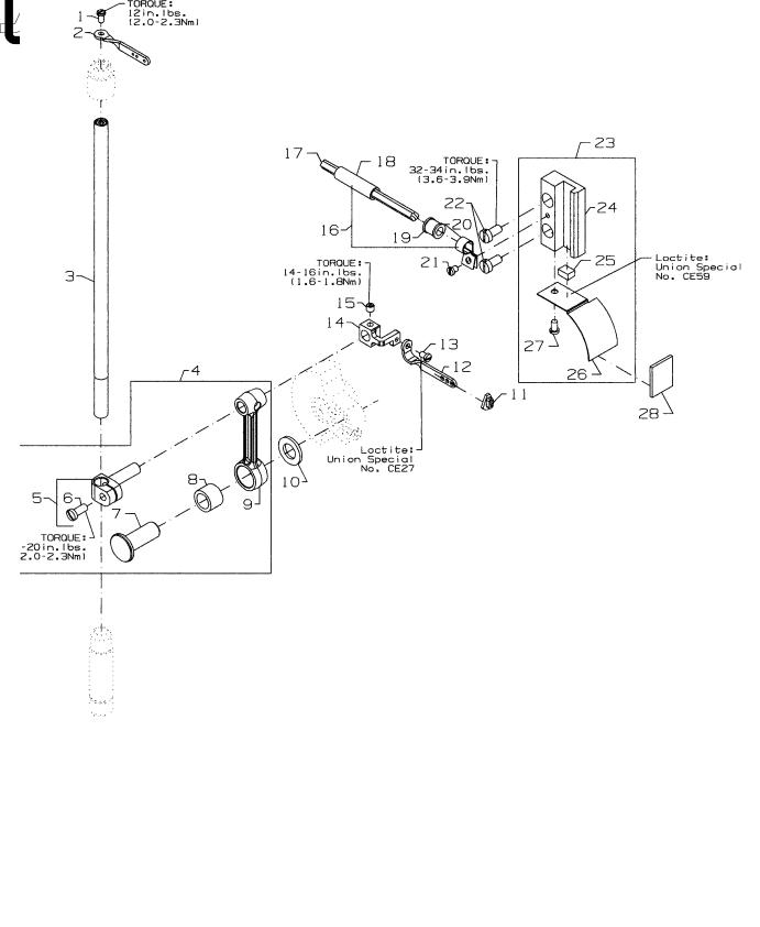
NEEDLE BAR |
|
Ref. |
|
|
Amt . |
No.. |
Part No. |
Description |
Req. |
1. |
SS4080620TP |
Screw .......................................................................................................... |
1 |
2. |
50323P |
Needle Bar Eyelet ....................................................................................... |
1 |
3. |
50317B |
Needle Bar .................................................................................................. |
1 |
4. |
50345W |
Connecting Rod Assembly ......................................................................... |
1 |
5. |
50355AM |
Needle Bar Clamp ................................................................................ |
1 |
6. |
SS7111120TP |
Screw ............................................................................................. |
1 |
7. |
50352 |
Pivot Pin ................................................................................................ |
1 |
8. |
661-259B |
Needle Bearing Cage ........................................................................... |
1 |
9. |
50355AN |
Connecting Rod ................................................................................... |
1 |
10. |
50351A |
Washer ........................................................................................................ |
1 |
11. |
50393JP |
Eyelet Seal ................................................................................................... |
1 |
12. |
50358X |
Needle Thread Eyelet ................................................................................. |
1 |
13. |
SS7080520SP |
Screw .......................................................................................................... |
1 |
- |
CE27 |
Loctite Adhesive, (not shown), for screw .................................................... |
- |
14. |
50354F |
Slide Block ................................................................................................... |
1 |
- |
CE63 |
Three Bond Adhesive, (not shown), for slide block ...................................... |
- |
15. |
SS8110422TP |
Screw .......................................................................................................... |
1 |
16. |
29476TC |
Oil Tube Assembly ....................................................................................... |
1 |
17. |
CQ25220000 |
Cable ................................................................................................... |
1 |
18. |
50393JY |
Oil Tube ................................................................................................. |
1 |
19. |
50393JZ |
Oil Tube ................................................................................................. |
1 |
20. |
50393JW |
Hose Clamp .......................................................................................... |
1 |
21. |
SS6090440SP |
Screw, for support bracket .......................................................................... |
1 |
22. |
SS6121010SP |
Screw .......................................................................................................... |
2 |
23. |
50354G |
Slide Block Guide ........................................................................................ |
1 |
24. |
50393HS |
Sponge ....................................................................................................... |
1 |
- |
CE59 |
Loctite Adhesive, (not shown), for sponge .................................................. |
- |
25. |
50394AF |
Slide Block Guide Cover .............................................................................. |
1 |
26. |
SS6090620SP |
Screw .......................................................................................................... |
1 |
11
12

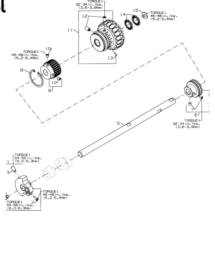
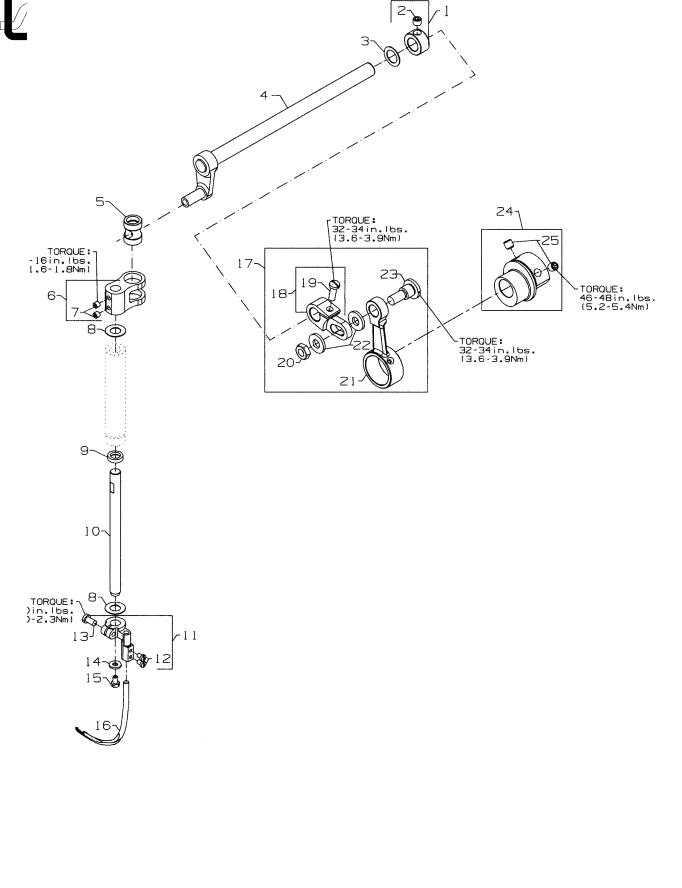
UPPER MAIN SHAFT
Ref. |
|
|
Amt . |
No.. |
Part No. |
Description |
Req. |
1. |
50391 |
Counter Weight .......................................................................................... |
1 |
2. |
SS7111120TP |
Screw, for counter weight .................................................................... |
1 |
3. |
SS8681412TP |
Screw, for counter weight .................................................................... |
1 |
4. |
SS7681410TP |
Screw, for counter weight .................................................................... |
1 |
5. |
50322AF |
Upper Main Shaft ........................................................................................ |
1 |
6. |
50335BD |
Bearing Adapter Assembly ......................................................................... |
1 |
7. |
SS8660612TP |
Screw, for bearing adapter .................................................................. |
2 |
8. |
661-262 |
Retaining Ring ............................................................................................. |
1 |
9. |
50342BE |
Sprocket, for upper main shaft .................................................................... |
1 |
10. |
SS8661012TP |
Set Screw, for sprocket ......................................................................... |
2 |
11. |
50321M |
Handwheel ................................................................................................. |
1 |
12. |
SS8681412TP |
Set Screw, for handwheel ..................................................................... |
2 |
13. |
660-1043 |
Tack Pin, for handwheel ....................................................................... |
1 |
14. |
661-261 |
Load Ring, for lower main shaft ................................................................... |
2 |
15. |
SS7660520SP |
Screw, for handwheel preload ................................................................... |
1 |
13
14

SPREADER
Ref..
No. Part No.
1.50335AW
2.SS8660512TP
3.96162B
4.50360B
5.50347J
6.50347C
7.SS8110422TP
8.61351C
9.660-739
10.50347G
11.50346A
12.SS7080510TP
13.SS7110910TP
14.53678N
15.SS9090640SP
16.50360H
17.29126FW
18.50360G
19.SS7121410TP
20.NS6680410SP
21.50360F
22.WP0742016SP
23.SD1000801SH
24.50360
25.SS8660612TP
|
Amt . |
Description |
Req. |
Collar, for spreader shaft ............................................................................ |
1 |
Set Screw .............................................................................................. |
1 |
Washer ........................................................................................................ |
1 |
Crankshaft, for spreader assembly ............................................................. |
1 |
Pin, for spreader rocker ............................................................................... |
1 |
Lever, for spreader holder shaft .................................................................. |
1 |
Screw .................................................................................................... |
2 |
Washer ........................................................................................................ |
2 |
Oil Seal ........................................................................................................ |
1 |
Shaft, for spreader, vertical ........................................................................ |
1 |
Spreader Holder .......................................................................................... |
1 |
Screw .................................................................................................... |
2 |
Screw .................................................................................................... |
1 |
Washer ........................................................................................................ |
1 |
Hex Screw, for vertical shaft ........................................................................ |
1 |
Spreader ..................................................................................................... |
1 |
Spreader Crank Rod Assembly .................................................................... |
1 |
Spreader Shaft Driving Arm ................................................................... |
1 |
Screw ............................................................................................. |
1 |
Hex Nut, for spreader drive ................................................................... |
1 |
Connecting Rod, for spreader drive ..................................................... |
1 |
Collar, for spreader driving arm ............................................................ |
2 |
Stud ...................................................................................................... |
1 |
Eccentric, for spreader drive ...................................................................... |
1 |
Screw .................................................................................................... |
2 |
15

16

THREAD GUIDE
Ref. |
|
|
Amt . |
No.. |
Part No. |
Description |
Req. |
1. |
SS7120640SP |
Screw, for lead-in eylet ............................................................................... |
2 |
2. |
50392AU |
Thread Eyelet Assembly .............................................................................. |
1 |
3. |
SS7090910TP |
Screw .................................................................................................... |
1 |
4. |
WS0510002KP |
Split Washer .......................................................................................... |
1 |
5. |
50366A |
Thread Eyelet Tube Bracket .................................................................. |
1 |
6. |
50392S |
Lead-In Tension Eyelet .......................................................................... |
1 |
7. |
50366 |
Thread Eyelet Tube ............................................................................... |
2 |
8. |
SS4120615SP |
Screw, for needle thread guide .................................................................. |
2 |
9. |
50363CK |
Needle Thread Guide and Lubricator Assembly ......................................... |
1 |
10. |
SS7110410SP |
Screw, for spreader thread guide ......................................................... |
1 |
11. |
50358U |
Thread Guide, for spreader .................................................................. |
1 |
12. |
50393HH |
Silicone Thread Lubricator .................................................................... |
1 |
13. |
WP0371026SD |
Washer ................................................................................................. |
2 |
14. |
50366J |
Needle Thread Guide ........................................................................... |
1 |
15. |
SS7080510TP |
Screw, for holder eyelet ........................................................................ |
1 |
16. |
SS4090815SP |
Screw, for silicone tank ......................................................................... |
2 |
17. |
50358W |
Holder, for needle thread eyelet .......................................................... |
1 |
18. |
SS8080410TP |
Screw ............................................................................................. |
3 |
19. |
36271A |
Adjusting Needle Thread Eyelet ............................................................ |
3 |
20. |
SS7120710SP |
Screw, for strike-off ..................................................................................... |
1 |
21. |
50366B |
Needle Thread Strike-Off Assembly ............................................................. |
1 |
22. |
SS7060310SP |
Screw, for plate strike-off ...................................................................... |
1 |
23. |
50370F |
Thread Strike-Off Component .............................................................. |
1 |
24. |
50358V |
Needle Thread Strike-Off ...................................................................... |
1 |
25. |
50392T |
Eyelet .......................................................................................................... |
1 |
26. |
605A |
Screw, for needle thread guide .................................................................. |
2 |
27. |
C50044E |
Needle Thread Guide ................................................................................. |
1 |
28. |
SS7090610SP |
Screw .......................................................................................................... |
1 |
29. |
12124202 |
Looper Frame Eyelet ................................................................................... |
1 |
30. |
29475CG |
Spreader Thread Tension Assembly ............................................................. |
1 |
31. |
50392AZ |
Tension Nut ........................................................................................... |
1 |
32. |
50392AY |
Tension Spring ....................................................................................... |
1 |
33. |
50392AX |
Tension Disc .......................................................................................... |
2 |
34. |
50392AW |
Tension Post .......................................................................................... |
1 |
35. |
57844 |
Eyelet .......................................................................................................... |
1 |
36. |
652C16 |
Star Washer ................................................................................................. |
1 |
37. |
SS7120640SP |
Screw .......................................................................................................... |
1 |
38. |
50392AE |
Looper Frame Eyelet ................................................................................... |
1 |
39. |
SS1121010SP |
Screw, for thread guide .............................................................................. |
1 |
40. |
50357AR |
Nipper Plate Assembly ................................................................................ |
1 |
41. |
SD0380551SL |
Screw .................................................................................................... |
1 |
42. |
50357AS |
Nipper Spring ........................................................................................ |
1 |
43. |
50357Y |
Nipper Spring Plate ............................................................................... |
1 |
44. |
50357V |
Nipper Plate .......................................................................................... |
1 |
45. |
50366G |
Thread Guide ........................................................................................ |
1 |
46. |
SS7090610SP |
Screw, for spreader thread guide ............................................................... |
2 |
47. |
50346 |
Thread Guide Spreader .............................................................................. |
1 |
17
18

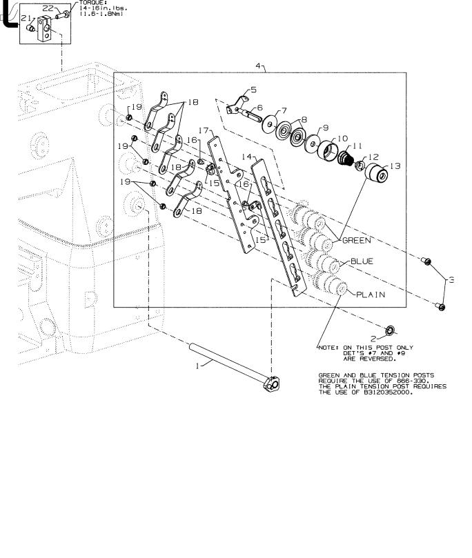
TENSION RELEASE & THREAD TENSION
Ref. |
|
|
Amt . |
No.. |
Part No. |
Description |
Req. |
1. |
50392Z |
Tension Needle Lever Assembly .................................................................. |
1 |
2. |
660-283A |
Retainer Washer ......................................................................................... |
1 |
3. |
SS4120915SP |
Screw, for tension assembly ........................................................................ |
2 |
4. |
50392Y |
5 Thread Tension Assembly .......................................................................... |
1 |
5. |
57892K |
Thread Tension Eyelet ........................................................................... |
5 |
6. |
56392G |
Tension Post .......................................................................................... |
5 |
7. |
B3120352000 |
Tension Disc Felt .................................................................................... |
1 |
- |
666-330 |
Disc Felt ................................................................................................ |
4 |
8. |
B3126012000 |
Tension Disc .......................................................................................... |
10 |
9. |
B3120704000 |
Tension Disc Felt .................................................................................... |
5 |
10. |
56392H |
Spring Shield ......................................................................................... |
5 |
11. |
11550209 |
Spring, needle (green) ......................................................................... |
3 |
- |
B3103804000 |
Spring, spreader (blue) ......................................................................... |
1 |
- |
B3121804000 |
Spring, looper (plain) ............................................................................ |
1 |
12. |
B3112704000 |
Ferrule, tension spring ........................................................................... |
5 |
13. |
50692G |
Knob, needle (green) ........................................................................... |
3 |
- |
56392M |
Knob, spreader (blue) .......................................................................... |
1 |
- |
56392R |
Knob, looper (plain) .............................................................................. |
1 |
14. |
50392W |
Tension Disc Separator ......................................................................... |
1 |
15. |
50392AV |
Guide, for tension disc separator .......................................................... |
2 |
16. |
SS7090520SP |
Screw, for guide .................................................................................... |
2 |
17. |
50392X |
Tension Bracket .................................................................................... |
1 |
18. |
57865 |
Lead-In Thread Guide ........................................................................... |
5 |
19. |
NS6110420SP |
Nut ........................................................................................................ |
5 |
20. |
50392BC |
Tension Release Lever Shaft Connection .................................................... |
1 |
21. |
22875N |
Base Spring Screw ................................................................................. |
1 |
22. |
SS7121410TP |
Binder Screw ......................................................................................... |
1 |
19

20
PRESSERFOOTLIFT
Ref. |
|
|
Amt . |
No.. |
Part No. |
Description |
Req. |
1. |
11071602 |
Adjusting Screw, for spring .......................................................................... |
1 |
2. |
11071701 |
Locking Nut ................................................................................................. |
1 |
3. |
660-1014 |
"O" Ring ....................................................................................................... |
1 |
4. |
C50056B |
Spring Rod .................................................................................................. |
1 |
5. |
50357AP |
Spring, for presser bar ................................................................................. |
1 |
6. |
50335AF |
Presser Bar .................................................................................................. |
1 |
7. |
SS6110610TP |
Screw, for guide plate ................................................................................ |
2 |
8. |
50335AG |
Guide Plate, for presser bar ........................................................................ |
1 |
9. |
50335AH |
Presser Bar Guide ........................................................................................ |
1 |
10. |
SS8110422TP |
Set Screw .............................................................................................. |
2 |
11. |
660-739 |
Oil Seal ........................................................................................................ |
1 |
12. |
50333P |
Collar .......................................................................................................... |
1 |
13. |
22562 |
Screw ................................................................................................... |
2 |
14. |
RE0500000K0 |
E Ring, for pin .............................................................................................. |
1 |
15. |
50381F |
Lever, for lifter, front .................................................................................... |
1 |
16. |
SD0790303SP |
Screw, for wire connector .......................................................................... |
1 |
- |
CE66 |
Loctite Adhesive, (not shown), for screw .................................................... |
- |
17. |
29476TK |
Rear Lifter Lever Assembly .......................................................................... |
1 |
18. |
SD0790303SP |
Screw ................................................................................................... |
1 |
19. |
50355AR |
Wire Connector .......................................................................................... |
1 |
20. |
50381G |
Lifter Lever, rear .......................................................................................... |
1 |
21. |
SS9151740CP |
Hex Screw ............................................................................................. |
1 |
22. |
29476TT |
Stop Assembly ............................................................................................ |
1 |
23. |
SS6121010SP |
Screw, for stopper ................................................................................ |
1 |
24. |
NS6150310SP |
Hex Nut ................................................................................................. |
2 |
25. |
50332V |
Stopper, for lifter lever .......................................................................... |
1 |
26. |
SS6153040SP |
Screw, for adjusting stopper ................................................................. |
1 |
27. |
SS6151920SP |
Screw, for adjusting stopper ................................................................. |
2 |
- |
CE66 |
Loctite Adhesive, (not shown), for screw .................................................... |
- |
28. |
50381 |
Spring, for lifter lever ................................................................................... |
1 |
29. |
RO068190100 |
"O" Ring ....................................................................................................... |
1 |
30. |
50381B |
Lifter Lever Assembly .................................................................................. |
1 |
21

22

COVERS, UPPER ARM
Ref. |
|
|
Amt . |
No.. |
Part No. |
Description |
Req. |
1. |
SS4121615SP |
Screw, for top cover .................................................................................... |
6 |
2. |
50393EU |
Plug, for top cover ....................................................................................... |
1 |
3. |
B3530555000 |
Oil Sight Gauge, top .................................................................................... |
1 |
4. |
660-212 |
"O" Ring, for oil sight gauge ......................................................................... |
1 |
5. |
50382FW |
Top Cover ................................................................................................... |
1 |
6. |
50382FZ |
Quad Ring, for top cover ............................................................................ |
1 |
7. |
SS7120640SP |
Screw, for needle bar guard ....................................................................... |
2 |
8. |
50317C |
Needle Bar Guard ....................................................................................... |
1 |
9. |
TA1050504R0 |
Plug, for bed ................................................................................................ |
1 |
10. |
50393HB |
Plug, for bed ................................................................................................ |
2 |
11. |
50384L |
Gasket, for puller drive cover ...................................................................... |
1 |
12. |
50382GB |
Puller Drive Cover ....................................................................................... |
1 |
13. |
SS4120915SP |
Screw, for puller drive cover ....................................................................... |
4 |
14. |
50382FY |
Quad Ring, for head cover ......................................................................... |
1 |
15. |
50382FX |
Head Cover ................................................................................................ |
1 |
16. |
SS4121215SP |
Screw, for head cover ................................................................................. |
4 |
17. |
TA1100604R0 |
Plug, for head cover ................................................................................... |
1 |
18. |
99682XCB |
Protection Shield Assembly, for all styles except FS322E12 & FS332E12 .... |
1 |
19. |
NS6620320SP |
Nut ........................................................................................................ |
1 |
20. |
50383AE |
Bracket Holder ...................................................................................... |
1 |
21. |
50383AD |
Bracket ................................................................................................. |
1 |
22. |
WZ0641510KP |
Spring Washer ....................................................................................... |
1 |
23. |
SD0640323TP |
Shoulder Screw ..................................................................................... |
1 |
24. |
SS6110610SL |
Counter Sunk Head Screw .................................................................... |
2 |
25. |
99682XC3 |
Protection Shield .................................................................................. |
1 |
26. |
50393EW |
Rubber Gasket, for needle lever ................................................................ |
1 |
27. |
50382GA |
Cover, for thread take-up ........................................................................... |
1 |
28. |
SS4120915SP |
Screw, for thread take-up cover ................................................................. |
1 |
29. |
SS4120615SP |
Screw, for thread cover .............................................................................. |
1 |
30. |
50382GM |
Thread Cover .............................................................................................. |
1 |
31. |
SS4120615SP |
Screw, for thread take-up cover ................................................................. |
1 |
32. |
LA452 |
Label, direction of rotation ......................................................................... |
1 |
23

24
 Loading...