


Union Special 81500A, 81500B, 81500B1H, 81500B2, 81500BA Parts List
...INSTRUCTIONS AND ILLUSTRATED PARTS MANUAL INSTRUCCIONES Y CATALOGO DE PARTES Y PIEZAS
81500B2
81500BA2
MIRAKLES SINGLE NEEDLE, SINGLE, TWO OR THREE THREAD OVERSEAMING MACHINES
MIRAKLES, MAQUINA OVERLOCK, DE UNA AGUJA, UNO, DOS O TRES HILOS
MANUAL NO. / CATALOGO NR. G234 FOR STYLES / PARA ESTILOS 81500A, B, B1H, B2, BA, BA1H, BA2, C, E
MANUAL NO. G234
INSTRUCTIONS AND ILLUSTRATED PARTS LIST
FOR 81500 SERIES MACHINES
Fitfth Edition Copyright 2002
by
Union Special GmbH Rights Reserved in All
Countries
Printed in Germany
PREFACE
This catalog has been prepared to guide you while operating 81500 series machines and arranged to simplify ordering spare parts.
This catalog explains in detail the proper settings for operation of the machines. Illustrations are used to show the adjustments and reference letters are used to point out specific items discussed.
Careful attention to the instructions and cautions for operating and adjusting these machines will enable you to maintain the superior performance and reliability designed and built into every Union Special bag sewing machine.
Adjustments and cautions are presented in sequence so that a logical progression is accomplished. Some adjustments performed out of sequence may have an adverse effect on the function of the other related parts.
This manual has been comprised on the basis of available information. Changes in design and / or improvements may incorporate a slight modification of configuration in illustrations or cautions.
On the following pages will be found illustrations and terminology used in describing the instructions and the parts for your machine.
In addition to the instructions and to the mandatory rules and regulations for accident prevention and environmental protection in the country and place of use of the machine / unit, the generally recognized technical rules for safe and proper working must also be observed.
The instructions are to be supplemented by the respective national rules and regulations for accident prevention and environmental protection.
CATALOGO Nº G234
INSTRUCCIONES Y LISTA DE PARTES ILUSTRADAS MODELOS SERIE 81500
Quinta Edición © 2002
Union Special GmbH
Derechos Reservados
en todos los paises del mundo Impreso en Alemania
INTRODUCCION
Este manual fue preparado para guiar al usuario en la operación de máquinas de la serie 81500 y ayudar para simplificar la elaboración de los pedidos de repuestos.
Este manual explica detalladamente los ajustes para la operación de la máquina. Las ilustraciones sirven para demostrar los ajustes y las letras en referencia indican los puntos específicos discutidos.
Una cuidadosa atención a las instrucciones y las precauciones operando y ajustando estas máquinas le va a permitir mantener el mejor funcionamiento y la confiabilidad que caracteriza las máquinas cosedoras de sacos de Union Special.
Los ajustes y precauciones son presentados en secuencia para que se consiga una progresión lógica. La ejecución de algunos ajustes fuera de la secuencia puede causar un efecto adverso para el funcionamiento de otras partes relacionadas.
Este manual se comprende a base de la información actual. Cambios en diseño y/o mejoras pueden significar leves modificaciones de la configuración de las ilustraciones o precauciones.
En las páginas siguientes se encuentran ilustraciones y terminologías usadas en la descripción de las instrucciones y las piezas de la máquina.
Adicionalmente a las instrucciones, las reglas y regulaciones obligatorias para prevenir accidentes y la protección ambiental del país y lugar donde se encuentra la máquina/unidad, hay que considerar las reglas técnicas para un trabajo seguro y adecuado.
Las instrucciones hay que complementarlas con las respectivas reglas y regulaciones nacionales contra accidentes y protección del ambiente.
2

TABLE OF CONTENTS
INDICE
SAFETY RULES
REGLAS DE SEGURIDAD
IDENTIFICATION OF MACHINES IDENTIFICACION DE LAS MAQUINAS
APPLICATION OF THIS INSTRUCTION MANUAL APLICACION DE ESTE MANUAL DE INSTRUCCIONES
STYLES OF MACHINES
ESTILOS DE MAQUINAS
INSTALLATION
INSTALACION
LUBRICATING
LUBRICACION
NEEDLES
AGUJAS
THREADING DIAGRAM
DIAGRAMAS DE ENHEBRADO
OPERATING INSTRUCTIONS
INSTRUCCIONES DE OPERACION
MAINTENANCE
MANTENIMIENTO
INSTRUCTION FOR MECHANICS INSTRUCCIONES PARA LOS MECANICOS
PAGE / PAGINA 4 - 5
5
5
6 - 7
8 – 11
12 - 13
13
14 – 15
16 – 18
19
20 - 31
ORDERING WEAR AND SPARE PARTS
INSTRUCCIONES PARA LOS PEDIDOS DE REPUESTOS
VIEWS AND DESCRIPTION OF PARTS
DIBUJOS Y DESCRIPCION DE LOS REPUESTOS
BUSHINGS, SIGHT FEED OILER, OILERS
BOCINAS Y PARTES DE LUBRICACION
CLOTH PLATE, BASE PLATE, GUARDS AND MISCELLANEOUS COVERS
TAPA Y BASE DE LA MAQUINA, GUARDAS Y OTRAS TAPAS
THREAD TENSIONS AND THREAD GUIDE PARTS
TENSIONES DE LOS HILOS Y PARTES DEL GUIA HILOS
NEEDLE BAR, NEEDLE LEVER, CRANKSHAFT, HANDWHEEL
BARRAS DE LA AGUJA, LEVANTADOR AGUJA, EJE PRINCIPAL, VOLANTE
LOOPER DRIVE MECHANISM
MECANISMO DE OPERACION DEL LOOPER
UPPER AND LOWER FEED DRIVE MECHANISM
MECANISMOS DEL TRANSPORTE SUPERIOR E INFERIOR
PRESSER BARS, PRESSER BAR SPRINGS AND PRESSER FOOT LIFTER LEVER
BARRAS DEL PIE PRENSATELA, MUELLES PARA LAS BARRAS DEL PIE PRENSATELA Y LEVANTADOR DEL PIE PRENSATELA
ELECTRO-PNEUMATIC PARTS KIT FOR UPPER FEED PRESSURE AND LIFTER FOR 81500B1H, B2, BA1H, BA2 WITH
ELECTRONIC DRIVE
PIEZAS DEL SISTEMA ELECTRO NEUMATICO PARA PRESION DEL PIE SUPERIOR Y PARA LEVANTAR EL PIE PRENSA TELA PARA 81500B1H, B2, BA1H, BA2 , CON MOTOR ELECTRONICO
CONTROL FOR ELECTRO-PNEUMATIC HOT THREAD CHAIN CUTTER FOR 81500B1H, BA1H
CONTROL PARA EL SISTEMA ELECTRO NEUMATICO CORTADOR CALIENTE DE CADENETA PARA 81500B1H, BA1H
ELECTRO-PNEUMATIC HOT THREAD CHAIN CUTTER FOR 81500B1H, BA1H
SISTEMA ELECTRO NEUMATICO CORTADOR CALIENTE DE CADENETA PARA 81500B1H, BA1H
SEWING PARTS; STYLES 81500A, B, B1H, B2, BA, BA1H, BA2 AND 81500C
PIEZAS DE FORMACION DE COSTURA, MODELOS 81500A, B, B1H, B2, BA, BAH1, BA2 Y 81500C
SEWING PARTS, STYLE 81500E
PIEZAS DE FORMACION DE COSTURA, MODELO 81500E
ACCESSORIES
ACCESORIOS
NUMERICAL INDEX OF PARTS
INDICE NUMERICO DE PARTES
32
33
34 – 35
36 – 37
38 – 41
42 – 43
44 – 45
46 - 47
48 - 49
50 - 51
52 - 55
56 - 57
58 - 59
60 - 61
63 - 64
65 - 66
3

SAFETY RULES
1.Before putting the machines described in this manual into service, carefully read the instructions. The starting of each machine is only permitted after taking notice of the instructions and by qualified operators.
IMPORTANT! Before putting the machine into service, also read the safety rules and instructions from the motor supplier.
2.Observe the national safety rules valid for your country.
3.The sewing machines described in this instruction manual are prohibited from being put into service until it has been ascertained that the sewing units which these sewing machines will be built into, have conformed with the provisions of EC Machinery Directive 98/37/EC, Annex II B.
Each machine is only allowed to be used as foreseen. The foreseen use of the particular machine is described in paragraph "STYLES OF MACHINES" of this instruction manual. Another use, going beyond the description, is not as foreseen.
4.All safety devices must be in position when the machine is ready for work or in operation. Operation of the machine without the appertaining safety devices is prohibited.
5.Wear safety glasses.
6.In case of machine conversions and changes all valid safety rules must be considered. Conversions and changes are made at your own risk.
REGLAS DE SEGURIDAD
1.Antes de poner en marcha las máquinas descritas en este manual, hay que leer cuidadosamente las instrucciones. El arranque de cada máquina solamente se permite después de haber leído las instrucciones y debe ser realizado por personal calificado.
IMPORTANTE! Antes de poner la máquina a operar, también hay que leer las reglas de seguridad y las instrucciones del fabricante del motor.
2.Observe las reglas nacionales de seguridad que rigen para su país.
3.No se puede poner en marcha la máquina descrita en este manual hasta que se confirme que la unidad de coser esta conforme con el reglamento del Directivo de las Máquinas de la Comunidad Europea 98/37/EC, Anexo II B.
La máquina solamente se puede utilizar para su uso previsto. El uso previsto esta descrito en el capitulo ESTILO DE MAQUINAS de este manual de instrucciones. Otro uso, diferente de la descripción, no esta previsto.
4.Todos los dispositivos de seguridad tienen que estar en su sitio cuando la máquina este lista para trabajar u operando. La operación de la máquina sin los dispositivos de seguridad esta prohibida.
5.Utilice lentes de seguridad.
6.En el caso de una modificación de la máquina hay que tomar en cuenta las reglas de seguridad. Modificaciones y cambios corren por su riesgo.
7.The warning hints in the instructions are marked with one of these two symbols.
8.When doing the following the machine has to be disconnected from the power supply by turning off the main switch or by pulling out the main plug.
8.1When threading needle(s), looper, spreader etc.
8.2When replacing any parts such as needle(s), presser foot, throat plate,
looper, spreader, feed dog, needle guard, folder, fabric guide etc.
8.3When leaving the workplace and when the work place is unattended.
8.4When doing maintenance work.
8.5When using clutch motors with or without
actuation lock, wait until motor is stopped totally.
7.Las advertencias en el manual de instrucciones están marcadas con las siguientes señales de aviso:
8.Para las siguientes maniobras hay que desconectar la máquina del suministro eléctrico desconectando el enchufe principal:
8.1Enhebrando agujas, looper y spreaders.
8.2Reemplazando piezas como agujas, pie prensa tela, plancha de aguja, looper, spreader, dientes
de arrastre, guarda aguja, dobladilladores, guía tela, cuchillas, etc.
8.3Cuando salga de su puesto de trabajo y no se
encuentre alguien para atender la máquina.
8.4Durante trabajos de mantenimiento.
8.5Utilizando motores de embrague sin freno, tie-
ne
que esperar que el motor pare completamente.
4

9.Maintenance, repair and conversion work (see item 8) 9. Mantenimiento, reparaciones y trabajos de conversión
must be done only by trained technicians ors p e c i a l skilled personnel under condsideration of the instructions.
Only genuine spare parts approved by UNION SPECIAL have to be used for repairs. These parts are designed specifically for your machine and manufactured with utmost precision to assure long lasting service.
10.Any work on the electrical equipment must be done by an electrician or under direction and supervision of special skilled personnel.
11.Work on parts and equipment under electrical power is not permitted. Permissible exceptions are described in the applicable section of standard sheet EN 50 110 / VDE 0105.
12.Before doing maintenance and repair work on the pneumatic equipment, the machine has to be disconnected from the compressed air supply. In case of existing residual air pressure after disconnecting from compressed air supply (e.g. pneumatic equipment with air tank), the pressure has to be removed by bleeding. Exceptions are only allowed for adjusting work and function checks done by special skilled personnel.
(véase No. 8) solamente pueden ser efectuados por técnicos entrenados o personal especializado bajo consideración de las instrucciones.
Solamente repuestos originales y aprobados por Union Special pueden ser utilizados para reparaciones. Estos repuestos han sido diseñados específicamente para estas máquinas, con precisión y para asegurar su máxima vida útil.
10.Cualquier trabajo con el equipo eléctrico tiene que ser ejecutado por un electricista o bajo la supervisión de personal especialmente entrenado.
11.No esta permitido trabajar en piezas y equipos con la electricidad conectada. Excepciones permitidas están descritas en EN 50110 / VDE 0105.
12.Antes de hacer mantenimiento o reparaciones del equipo neumático, hay que desconectar la máquina de la alimentación del aire comprimido. En el caso que exista una presión de aire residual después de desconectar la máquina (por ejemplo equipos con tanques de aire), la presión tiene que ser eliminada abriendo las válvulas. Excepciones están solamente permitidas para trabajos de ajuste y revisión de funciones por personal especialmente entrenado.
IDENTIFICATION OF MACHINES |
IDENTIFICACION DE LAS MAQUINAS |
Each UNION SPECIAL 81500 series machine is identified by a style number, which is stamped on the style plate affixed to the right front of machine. Serial number is stamped into bed casting at the right front base of machine.
Cada máquina UNION SPECIAL 81500 está identificada por un número de estilo, el cual está estampado en la placa fijada a la máquina. El número de serial está troquelado en la carcasa de la máquina.
APPLICATION OF THIS INSTRUCTION MANUAL |
APLICACIONES DE ESTE MANUAL DE INSTRUCCIONES |
NOTE: Instructions stating direction or location such as right left, front or rear of machine, are given relative to operator’s position at the machine, unless otherwise noted.
The handwheel pulley rotates clockwise, in operating direction, when viewed from the right end of machine.
NOTA: Instrucciones que se refieren a direcciones y posiciones como derecho, izquierdo, adelante o atrás se entienden desde el punto de vista de un operador sentado enfrente de la máquina, si no está notificado de una manera diferente.
El manubrio del volante gira en sentido del reloj, en su dirección de operación, cuando es visto desde la par te derecha del final de la máquina.
CAUTION! Before putting into service check the direction of rotation. Breakage may occur when the direction of rotation is wrong.
PRECAUCION: Revise antes de poner la máquina en marcha el sentido de la rotación. El sentido de rotación equivocado puede causar roturas.
5
STYLES OF MACHINES
„MIRAKLES“ single needle, single two and three thread overseamers with 71 mm (2 51/64 in.) needle throw. Manual lubrication.
81500A: Two thread machine. For even matched seaming of heavy bag fabrics made from jute. Perfect start of seam. Uniform, neat seam.
Plain feed with only swinging upper feed. Teeth cut 5 mm (5 teeth per inch). Seam specification 502/SSa-1. Standard seam width 19 mm (3/4 in.).
Parts for 10, 12 and 15 mm (25/64, 15/32 and 19/32 in.) seam width come with the machine.
Sewing capacity:
At 19 mm (3/4 in.) seam width up to 16 mm (5/8 in.) At 15 mm (19/32 in.) seam width up to 19 mm (3/4 in.) At 12 mm (15/32 in.) seam width up to 21 mm (13/16 in.) At 10 mm (25/64 in.) seam width up to 22 mm (7/8 in.) Standard recommended needle type 9859G
430/172. **
Stitch range 6 to 13 mm (2 to 4 SPI). Standard setting 10 mm (2 1/2 SPI).
Working dia. of handwheel pulley 150 mm (5 29/32 in.). Speed up to 1400 stitches per minute, depending on fabric and sewing operation.
Recommended operating speed 1200 stitches per minute. Equivalent continuous A-weighted sound pressure level on work stations at recommended operating speed: 84 dB(A)*
Weight net: 36 kg
81500B: Two thread machine. For even matched seaming of container bags made from woven polypropylene and simultaneously attaching regular, loosely woven belt bands with polypropylene sewing threads.
Plain feed with synchronized upper feed. Teeth cut 5 mm (5 teeth per inch). Seam specification 502/SSa-1. Standard seam width 19 mm (3/4 in.).
Parts for 10, 12 and 15 mm (25/64, 15/32 and 19/32 in.) seam width come with the machine.
Sewing capacity:
At 19 mm (3/4 in.) seam width up to 16 mm (5/8 in.)
At 10 (25/64 in.), 12 (15/32 in.), and 15 mm (19/32 in.) seam width up to 19 mm (3/4 in.)
Standard recommended needle type 9859G 300/120 **.
Stitch range 6 to 13 mm (2 to 4 SPI). Standard setting 10 mm (2 1/2 SPI).
Working dia. of handwheel pulley 150 mm (5 29/32 in.).
* Noise measurement according to DIN 45635-48 / ISO 10 821
** Please note page 13
ESTILOS DE MAQUINAS:
„MIRAKLES“ máquina overlock de una aguja, uno, dos o tres hilos, con un recorrido de la barra de aguja de 71 mm. Lubricación manual.
81500A: Máquina de dos hilos. Para emparejar piezas sueltas en sacos de yute. Comienzo perfecto de la costura. Costura limpia, uniforme y pareja.
Costura simple con alimentador superior solamente oscilando.
Distancia entre dientes: 5 mm Especificación de costura 502/Ssa-a Ancho de costura estándar 19 mm
Partes para 10, 12 y 15 mm vienen con la máquina.
Capacidad de costura:
Ancho de costura 19 mm: hasta 16 mm
Ancho de costura 15 mm: hasta 19 mm
Ancho de costura 12 mm: hasta 21 mm
Ancho de costura 10 mm: hasta 22 mm
Aguja normal recomendada: 9859G430/172. **
Rango de puntada 6 a 13 mm. Ajuste de fabrica 10 mm.
Diámetro efectivo del volante 150 mm.
Velocidad de hasta 1400 Puntadas / min., dependiendo del material y la operación de costura.
Velocidad de operación recomendada 1200 Puntadas / min.
Nivel de ruido de la unidad referente al puesto de trabajo con la velocidad de operación recomendada 84dB (A)
Peso, neto 36 kgs
81500B: Máquina de dos hilos. Para emparejar piezas sueltas en sacos de polipropileno tejido y simultáneamente pegar correas suaves de material de polipropileno de alta tenacidad.
Costura simple con alimentador superior sincronizado. Distancia entre dientes: 5 mm
Especificación de costura 502/Ssa-a Ancho de costura standard 19 mm
Partes para 10, 12 y 15 mm vienen con la máquina.
Capacidad de costura:
A 19 mm: hasta 16 mm.
A 10, 12 y 15 mm: hasta 19 mm
Aguja normal recomendada: 9859G430/172. **
Rango de puntada 6 a 13 mm. Ajuste de fabrica 10 mm.
Diámetro efectivo del volante 150 mm.
*Medición de ruido, según norma DIN 45635-48 / ISO 10 821
** Por favor, vea NOTA en página 13
6
Speed up to 1400 stitches per minute, depending on fabric and sewing operation.
Recommended operating speed 1200 stitches per minute.
Equivalent continuous A-weighted sound pressure level on work stations at recommended operating speed: 81 dB(A)*
Weight net: 37 kg
81500B1H: Same as 81500B, but with built-in electropneumatically operated hot thread chain cutter. Electropneumatically operated presser foot and
upper feed dog lifter. Pneumatic presser foot spring.
Guides for filler cord from the top and / or from below for sealing the needle punctures of the left needle.
81500B2: Same as 81300B1H, but without any thread chain cutter.
81500BA: Same as 81500B except for simultaneously attaching tightly woven, heavy belt bands.
Standard recommended needle type 9859G430/172 **
81500BA1H: Same as 81500BA, but with built-in electropneumatically operated hot thread chain cutter. Electropneumatically operated presser foot and
upper feed dog lifter. Pneumatic presser foot spring.
Guides for filler cord from the top and / or from below for sealing the needle punctures of the left needle.
81500BA2: Same as 81500BA1H, but without any thread chain cutter.
81500C: Three thread machine. Same as 81500 B, except three thread seam, stitch type 504.
81500E: Single thread machine. For even matched, butted joining medium to heavy weight webs of fabric for finishing and dyeing purposes.
Plain feed with synchronized upper feed. Alternating upper feed dog and presser foot. Teeth cut 5 mm (5 teeth per inch).
Seam specification 501/ FSf-1.
Seam width 19 mm (3/4 in.). Width of abutted seam 35 mm (1 3/8 in.).
Sewing capacity 13 mm (33/64 in.).
Standard recommended needle type 9859G300/120 ** Stitch range 6 to 13 mm (2 to 4 SPI).
Standard setting 10 mm (2 1/2 SPI).
Working dia. of handwheel pulley 150 mm (5 29/32 in.). Speed up to 1400 stitches per minute, depending on fabric and sewing operation.
Recommended operating speed 1200 stitches per minute. Equivalent continuous A-weighted sound pressure level on work stations at recommended operating speed: 81 dB(A)* Weight net: 37 kg.
*Noise measurement according to DIN 45635-48 / ISO 10 821
**Please note page 13
Velocidad de hasta 1400 Puntadas / min., dependiendo del material y la operación de costura.
Velocidad de operación recomendada 1200 Puntadas / min.
Nivel de ruido de la unidad referente al puesto de trabajo con la velocidad de operación recomendada81dB (A)
Peso, neto |
37 kg. |
81500B1H: Igual a la 81500B, pero con cortador electroneumático caliente de cadeneta y pie prensatelas y levantador del diente superior activados electroneumáticamente.
Pie prensatelas con presión neumática por pistón.
La máquina está equipada con una guía superior e inferior de los cordeles para sellar las perforaciones de las agujas desde arriba y/o desde abajo de la aguja izquierda.
81500B2: Igual a la 81500B1H, pero sin ningún cortador de cadeneta.
81500BA: Igual a la 81500B, excepto que simultáneamente se pueden pegar correas tejidas de rafia.
Tipo de aguja recomendada 9859G430/172 **
81500BA1H: Igual a la 81500BA, pero con cortador electroneumático caliente de cadeneta y pie prensatelas y levantador del diente superior operados electroneumáticamente.
Pie prensatelas con presión neumática por pistón.
La máquina está equipada con una guía superior e inferior de los cordeles para sellar las perforaciones de las agujas desde arriba y/o desde abajo de la aguja izquierda.
81500BA2: Igual a la 81500BA1H, pero sin ningún cortador de cadeneta.
81500C: Máquina de 3 hilos, Igual a la 81500 B, pero con 3 hilos. Tipo de costura 504.
81500E: Máquina de un solo hilo, para coser tejidos medianos y pesados sin desplazamiento y pegado a tope, para acabado posterior de tintorería.
Transporte alimentador simple con diente superior sincronizado. Diente superior alternando con el pie prensatelas. Distancia entre dientes: 5 mm
Especificación de costura 501/ FSf-1. Ancho de costura 19 mm: hasta 35 mm.
Capacidad de costura: 13 mm.
Aguja normal recomendada 9859G300/120 ** Rango de puntada 6 a 13 mm.
Ajuste de fabrica 10 mm.
Diámetro efectivo del volante 150 mm.
Velocidad de hasta 1400 Puntadas / min., dependiendo del material y la operación de costura.
Velocidad de operación recomendada 1200 Puntadas / min. Nivel de ruido de la unidad referente al puesto de trabajo con la velocidad de operación recomendada81dB (A)
Peso, neto |
37 kg. |
*Medición de ruido, según norma DIN 45635-48 / ISO 10 821
**Por favor, vea NOTA en página 13
Use UNION SPECIAL sewing tables for the described sewing machines. UNION SPECIAL sewing tables complete the particular sewing machine to a sewing unit and guarantee safe operation as well as the indicated data of the sound pressure level generated by the sewing unit.
Utilize montajes de UNION SPECIAL para las máquinas descritas. Mesas y pedestales de UNION SPECIAL complementan las máquinas de coser a una unidad de coser y garanti-
zan una operación segura y los niveles de ruido.
7
INSTALLATION |
INSTALACION |
8

INSTALLATION (continued) |
INSTALACION (Continuación) |
||
1. |
Unpack the sewing machine and the accessories. |
1. |
Desempaque la máquina y los accesorios. |
|
|
||
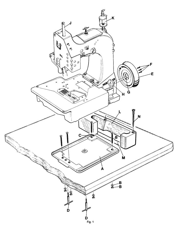
2. |
Mount the base plate (A, Fig. 1) with four screws, nuts |
2. |
Monte la placa de base (A, Fig. 1) con los 4 tornillos, |
|
and washers (B) in the provided holes on the table board. |
|
tuercas y arandelas (B) en los huecos previstos en la |
|
|
tabla de la mesa. |
|
|
|
|
|
3. |
Place the sewing machine on the base plate so that the |
3. |
Coloque la maquina sobre la base, de manera que el |
|
roll pin (C) in the base plate engages with the right rear |
|
pasador de regulación (C) en la placa base, encaje en |
|
hole in the machine base. |
|
el hueco derecho trasero de la base de la máquina. |
4. |
Fasten the sewing machine with the two T-screws (D) on |
4. |
Asegure la máquina de coser con los 2 tornillos T (D) |
|
the base plate. |
|
en la placa de base. |
|
|
|
|
5. |
Place the V-belt, supplied with the sewing table, on the |
5. |
Coloque la correa en forma de V, en la rueda del vo- |
|
handwheel pulley . |
|
lante. |
|
|
|
|
6.Assemble the handwheel pulley (E) with three 6. Monte el volante (E) con los 3 tornillos remache (F) a
countersunk screws (F) to the sewing machine. Pin (G) must engage with the hole in hub (H).
la máquina de coser. El pasador (G) debe encajar en el hueco de la parte central del volante (H).
7.Screw in needle bar guard (J).
8.Screw in sight feed oiler (K).
9.Align the handwheel belt guard (L) with the V-belt slot
(M) in the table board and with the handwheel pulley and fasten it with two wood screws (N) on the table board.
10.Dismount motor belt guard. Place the V-belt around the motor pulley and slue the motor to tense the belt. The tension on the V-belt is correct, when with moderate finger pressure it will deflect approx. 10 mm (3/8 in.) midway between handwheel pulley on the sewing machine and motor pulley (see Fig. 2).
Remount motor belt guard.
7.Atornille el protector de la barra de aguja (J).
8.Asegure la aceitera (K).
9.Alinie el guarda correa del volante (L) con la perforación para la correa en la mesa (M) y con la rueda del volante y sujetelo con los 2 tornillos para madera (N) a la mesa.
10.Desmonte el guarda correa del motor. Coloque la correa en V alrededor del volante y ajuste el motor para tensar la correa. La tensión de la correa en V será la correcta cuando ejerciendo presión moderada con el dedo ceda en aprox. 10mm (3/8 pulgada) en la mitad entre la rueda del volante en la maquina de coser y la rueda del motor (Ver Fig. 2).
Coloque nuevamente el guarda correa del motor.
9
10
INSTALLATION (continued) |
INSTALACION (Continuación) |
|
|
|
|
11.Hook the lifter chain to the lifter lever of the sewing 11. Enganche la cadena a la palanca levantadora de la
machine and to the small treadle on the sewing table.
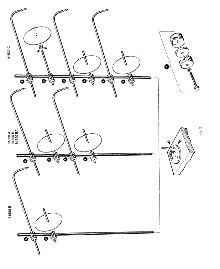
12.Assemble the thread stand and mount the thread stand base with three wood screws on the right rear corner of the table board.
13.Before being put into service note the specified service voltage and frequency of the motor. Check if the mains voltage and frequency at site correspond with the factory specified service voltage and frequency.
14.Check the direction of rotation. The handwheel pulley must rotate clockwise (to the right), when viewed from the right end of the machine.
Switch on the motor. Only shortly and very slightly depress the motor treadle and check the direction of rotation. Immediately release the treadle. Switch off and wait until the motor has stopped.
máquina de coser y al pequeño pedal en la mesa de la máquina de coser.
12.Asegure la base del porta conos con tres tornillos al lado derecho de la mesa de la máquina de coser y monte el porta conos.
13.Antes de comenzar a utilizar la máquina, verifique que el voltaje y la frecuencia del motor coinciden con la instalada en el lugar donde operará la máquina.
14.Verifique la dirección de rotación. El volante debe girar en dirección del reloj (a la derecha), cuando es visto desde la parte derecha de la máquina.
Encienda el motor. Presione ligeramente el pedal y chequee la dirección de rotación. Suéltelo inmediatamente. Apague el motor y espere hasta que se detenga totalmente.
CAUTION! In case the direction of rotation has to be changed, the reversing of the polarity is only allowed to be done by a skilled electrician.
PRECAUCION! En el caso que la dirección de rotación deba ser cambiada, la reversión de la polaridad debe ser realizada por un electricista calificado.
11

LUBRICATING
Turn off main power switch before lubricating! When using clutch motors with or without actuation lock wait until motor has completely stopped.
LUBRICACION
Antes de lubricar, apague el interruptor principal. Con un motor de embrague sin freno espere hasta que el motor se detenga completamente!
12
LUBRICATING (continued)
PREPARING FOR OPERATING
Before operating a new machine for the first time, the sight feed oiler has to be adjusted. All lubrication points, indicated on the oiling diagram (Fig. 4), have to be oiled.
For adjusting fill the sight feed oiler half-way with oil and turn the metering pin (A, Fig. 4) a little bit out and then turn it in, until there will flow two to three drops of oil per minute. This can be checked on the sight glass (B). Secure the setting of the metering pin with lock nut (C). Fill the oiler.
Repeat the oiling of a new machine after 10 minutes of operation!
When the machine is out of operation, the oil flow can be stopped by tilting lever (D).
IMPORTANT!The oil flow has to be switched on again before operating the machine.
LUBRICACION (Continuación)
INSTRUCCIONES DE OPERACION
Antes de poner en marcha una nueva máquina por la primera vez, hay que fijar y ajustar el engrasador cuentagotas. Lubrique todos los puntos indicados en el diagrama de lubricación (Fig. 4).
Llene el engrasador cuentagotas hasta la mitad con aceite y ajuste girando el pasador de la regulación (A, Fig. 4) en tal manera que suministre aproximadamente dos gotas de aceite por minuto. Este ajuste se puede revisar a través del vidrio (B). Asegure la posición del pasador de la regulación con la contratuerca (C). Llene el engrasador cuentagotas con aceite. Para máquinas nuevas, repita la lubricación después de diez minutos de operación.
Si la máquina no está operando se puede parar el flujo del aceite doblando la palanca (D) del engrasador cuentagotas.
Nota: El flujo de aceite tiene que ser restablecido antes de operar la máquina otra vez.
For lubrication we recommend "Mobil Oil DTE Medium" or equivalent, which can be purchased from UNION SPECIAL in 1/2 liter containers under part number G28604L or in 5 liter containers under part number G28604L5.
NEEDLES
Each needle has both a type and size number. The type number denotes the kind of shank, point, length, groove, finish and other details. The size number, stamped on the needle shank, denotes the largest diameter of the blade, measured midway between the shank and the eye. Collectively, type and size number represent the complete symbol, which is given on the label of all needle packs and sold by UNION SPECIAL.
Para la lubricación recomendamos „Mobil Oil DTE Medium“ o un aceite equivalente, que se puede pedir a UNION SPECIAL en contenedores de ½ litro bajo el número de referencia G28604L y en contenedores de 5 litros bajo el número de referencia G28604L5.
AGUJAS
Cada aguja tiene un número de sistema y un número del grosor. El número del sistema se refiere al tipo del cabo, la punta, el largo, la ranura, acabado y otros detalles. El número del grosor, troquelado en el cabo, indica el grosor máximo de la caña, medido en la mitad de la distancia entre cabo y ojo de la aguja. El número del sistema y del grosor dan la descripción completa, que se encuentra en todos los empaques de agujas vendidas por UNION SPECIAL.
TYPE AND DESCRIPTION
9859G Round shank with seat, round point (size 300/120) or rounded square point (size 430/172), single groove, spotted, ball eye, chromium plated.
Sizes available: 300/120, 430/172.
NEEDLE ORDERING
To have needle orders promptly and accurately filled, an empty package, a sample needle or the type and size number should be forwarded. Use the description on the label.
The standard needle for styles 81500B, B1H, B2, 81500C and 81500E is 9859G300/120*.
The standard needle for styles 81500A, BA, BA1H, BA2 is 9859G430/172.*
A complete order should read as follows: 100 needles, type 9859G, size 300/120*.
*Please note, shorter needles 9853GA300/120 and 9853GA430/172 are also available.
TIPO Y DESCRIPCION
9859G Cabo redondo con superificie plana para asentar la aguja, punta redonda (Tamaño 300/120) o punta cuadrada redondeada (Tamaño 430/172), ranura simple,rebajo,ojo reforzado, cromado.
Tamaños disponibles: 300/120, 430/172.
PEDIDO DE AGUJAS
Para garantizar un despacho correcto y rápido les sugerimos enviarnos el empaque vacío de las agujas ó una aguja de muestra ó indicar el sistema con el grosor. Utilíze la descrip-
ción de la etiqueta en el empaque de la aguja.
La aguja normal recomendada para los estilos 81500B, B1H, B2, 81500C y 81500E es la 9859G300/120*.
La aguja normal recomendada para los estilos 81500A, BA, BA1H, BA2 es la 9859G430/172.*
Un pedido completo de agujas sería por ejemplo: 100 agujas, tipo 9859G, Grosor 300/120.*
*Por favor, tome en cuenta que tambien tenemos disponibles agujas mas cortas 9853GA300/120 y 9853GA430/172.
13
THREADING DIAGRAM
CAUTION! Turn off main power switch before threading! When using clutch motors with or without actuation lock wait until the motor has completely stopped!
DIAGRAMA DE ENHEBRADO
PRECAUCION! Apague el motor principal antes de enhebrar!. Cuando utilice motor con clutch debe esperar hasta que el mismo se detenga totalmente!.
14
THREADING DIAGRAM
CAUTION! Turn off main power switch before threading! When using clutch motors with or without actuation lock wait until the motor has completely stopped!
DIAGRAMA DE ENHEBRADO
PRECAUCION! Apague el motor principal antes de enhebrar!. Cuando utilice motor con clutch debe esperar hasta que el mismo se detenga totalmente!.
15

OPERATING INSTRUCTIONS
THREADING
CAUTION! Turn off main power switch before threading! When using clutch motors with or without actuation lock wait until the motor has stopped!
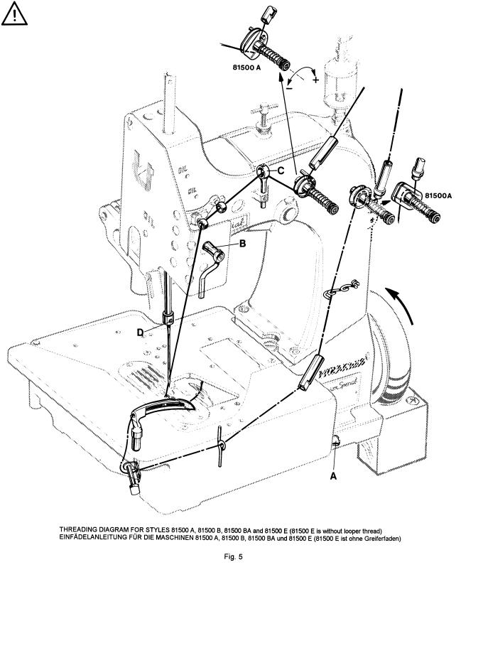
Styles 81500A, B, B1H, B2, BA, BA1H, BA2 and 81500E are threaded as shown in Fig. 5.
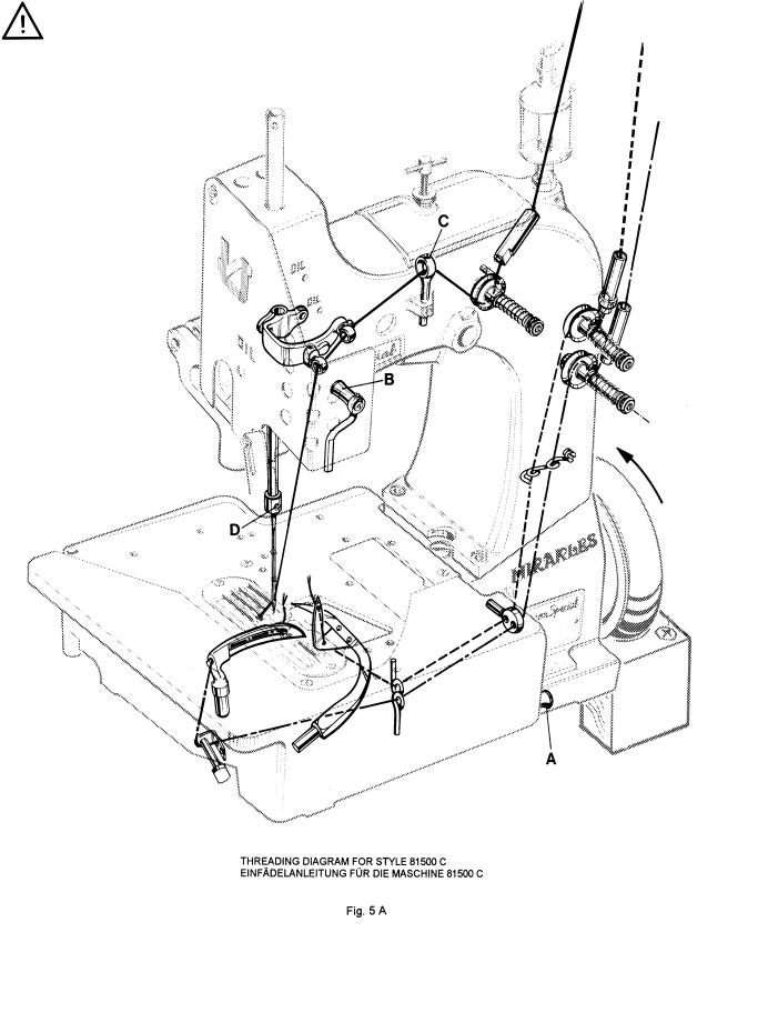
Style 81500C is threaded as shown in Fig. 5 A.
For threading the needle turn handwheel in operating direction until the needle is in the upmost position.
For looper threading open the hinge plate by lifting locking bolt knob (A, Figs. 5 and 5 A).
Reclose hinge plate after threading.
OPERATING
1.Switch on main power switch.
2.Without lifting the presser foot, place the fabric to be sewn as close as possible in front of the needle and to the right on the edge guide.
CAUTION! Remove the foot from the motor treadle, to avoid inadvertently starting of the machine, in case it is necessary to lift presser foot and upper feed dog for aligning the fabric to be sewn!
3.Depress the motor treadle. The machine sews. Guide the fabric to be sewn.
CAUTION! Keep a security distance of approx. 100 mm (4 in.) between hand and sewing needle when guiding the fabric to be sewn!
4.Release the motor treadle. The machine stops. Cut the thread chain at the trailing edge of the fabric and remove the fabric from the machine.
INSTRUCCIONES DE OPERACION
DIAGRAMA DE ENHEBRADO
PRECAUCION! Apague el motor principal antes de enhebrar!. Cuando utilice motor con clutch debe esperar hasta que el mismo se detenga totalmente!.
Para enhebrar estilos 81500A, B, B1H, B2, BA, BA1H, BA2 y 81500E, por favor vea diagrama en Fig. 5.
Para enhebrar estilo 81500C, por favor vea diagrama en Fig. 5 A.
Para enhebrar la aguja gire el volante en sentido de operación hasta que la aguja se encuentre en su posición superior. Para enhebrar el looper abra la tapa delantera levantando el tornillo de manivela (A, Figs.5 y 5A).
Cierre la tapa delantera otra vez.
OPERACION
1.Active el interruptor principal.
2.Ponga las telas lo más cercano posible delante de la aguja y a la derecha a la guía tope, sin levantar el pie prensatela.
PRECAUCION! Quite el pie del pedal del motor para no arrancar la máquina accidentalmente, si fuera necesario levante el pie prensatela y el transporte superior manualmente para guiar las telas.
3.Pise el pedal de motor hacia adelante. La máquina cose. Guíe las telas.
PRECAUCION! Mantenga una distancia de por lo menos 100 mm entre la aguja y la mano mientras guíe las telas!
4.Suelte el pedal del motor. La máquina se parará. Corte la cadeneta al final de las telas cosidas y quite los sobrantes de la superficie de la máquina.
16

NEEDLE THREAD TAKE-UP
Basically the needle thread take-up roller (B, Figs. 5 and 5A), located left on the upper bed casting under the face cover, is set as low as possible.
In case more needle thread should be pulled off for a bigger needle thread loop (depending on thread and fabric), raise the needle thread take-up roller accordingly.
Fasten the needle thread guide (C, Figs. 5 and 5A), located on the top of the upper bed casting, approx. in the middle of its shank.
THREAD TENSION
Regulate the tension on the threads so that uniform stitches are produced.
In general the tension applied to the needle thread is slightly higher than the tension applied to the looper thread(s).
Turning the tension nuts clockwise increases the tension, turning counterclockwise decreases the tension.
CHANGING THE NEEDLE
CAUTION! |
Turn off main power switch before |
|
changing the needle! When using clutch |
|
motors with or without actuation lock wait |
|
until the motor has stopped! |
Turn the handwheel pulley in operating direction until the needle is in its upmost position.
Unthread the eye of the needle to be changed.
Loosen screw (D, Figs. 5 and 5A) for the needle and pull out the needle. Insert the shank of the new needle as far as it will go and with the long groove of the needle facing to the front (toward the operator). Tighten screw (D) on the seat of the needle shank and thread the needle eye.
EDGE GUIDE AND STITCH TONGUE
CAUTION! Turn off main power switch before setting edge guide and stitch tongue and changing the seam width! When using clutch motors with or without actuation lock wait until the motor has stopped!
Styles 81500A, B, B1H, B2, BA, BA1H, BA2 and 81500C, see Fig. 6.
Style 81500E, see Fig. 6 A.
ALIMENTACION DEL HILO DE LA AGUJA
Generalmente el rodillo del alimentador del hilo de la aguja (B, Figs. 5 y 5A), que está situado en la parte delantera izquierda del brazo debajo de la tapa frontal, debería estar fijado tan bajo como sea posible.
En el caso que se necesite más hilo para crear un lazo de hilo más grande (dependiendo del hilo y tela) tiene que subir el rodillo adecuadamente.
Fije el guía hilo (C, Fig. 5 y 5 A), que está situada en la parte delantera superior del brazo, aproximadamente en la mitad de su mango.
TENSION DE LOS HILOS
Regule la tensión de los hilos de tal manera que se logre una formación uniforme de la costura.
Normalmente el hilo de la aguja tiene más tensión que el hilo del looper.
Girar las tuercas del tensor en sentido de reloj aumenta la tensión, girar en sentido contra el reloj la disminuye.
CAMBIO DE AGUJA
PRECAUCION! Antes de cambiar la aguja, apague el interruptor principal de la máquina. Con un motor de embrague sin freno, espere hasta que el motor se detenga completamente!
Gire el volante en sentido de operación hasta que la aguja se encuentre en su posición superior.
Retire el hilo del ojo de la aguja.
Suelte el tornillo fijador de la aguja (D, Fig. 5 y 5 A) y quite la aguja. Inserte la nueva aguja en tal manera que el cabo de la aguja toque el final de la barra de la aguja y la ranura de la aguja esté posicionada hacia adelante en dirección al operador. Apriete el tornillo (D) otra vez en la superficie plana para asentar la aguja y enhebre el hilo por el ojo de la aguja.
GUIA TOPE Y LENGUETA DE COSTURA:
PRECAUCION! Antes de cambiar la guía tope y la lengüeta de costura, apague el interruptor principal de la máquina. Con un motor de embrague sin freno, espere hasta que el motor se detenga completamente!
Para estilos 81500A, B, B1H, B2, BA, BA1H, BA2 y 81500C, favor ver Fig. 6.
Para estilo 81500E, vea Fig. 6 A.
17
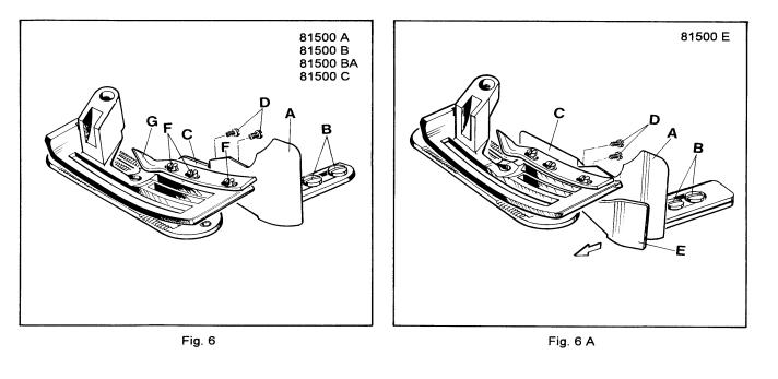
Set the edge guide (A, Figs. 6 and 6 A) laterally as close as possible to the presser foot, without contacting it. When loosening the two screws (B), the edge guide (A) can be moved laterally. Retighten screws.
Set the stitch tongue (C, Figs. 6 and 6 A) so that the rear part of the thread loop slides over the tongue onto the fabric, while the front part of the loop is retained until the needle securely has entered the loop. After loosening screws (D) the stitch tongue (C) can be moved to the front or to the rear. When moving the stitch tongue to the rear, the front part of the thread loop is retained longer. Retighten screws
(D).
On its travel the upper spreader or upper looper should not contact stitch tongue (C).
ADJUSTABLE EDGE GUIDE
Style 81500E
Set the adjustable edge guide (E, Fig. 6 A) so far to the left that the edges of the joined fabric webs are butted when opening the seam.
CHANGING THE SEAM WIDTH
Styles 81500A, B, B1H, B2, BA, BA1H, BA2 and 81500C
The machines are set at the factory to a seam width of 19 mm (3/4 in.) Presser foot tongues for 10 mm (25/64 in.), 12 mm 15/32 in.) and 15 mm (19/32 in.) are added to the machines.
For changing the seam width remove the three screws (F, Fig. 6) and interchange the presser foot tongue (G) with the presser foot tongue for the required seam width. Fasten the tongue with the three screws (F).
Set the edge guide (A) laterally as close as possible to the presser foot tongue without contacting it.
Readjust the thread tension, if required.
Ajuste la guía tope (A, Figs. 6 y 6A) tan cerca como sea posible al pie prensatelas, pero sin tocarlo. Cuando suelte los dos tornillos (B) la guía tope (A) podrá moverse lateralmente. Reajuste los tornillos de nuevo.
Ajuste la lengüeta de costura (C, Figs. 6 y 6 A) , de manera tal que la parte trasera del lazo del hilo desliza sobre la lengüeta hacia el tejido, mientras la parte delantera del lazo del hilo queda retenida hasta que la aguja entra al lazo del hilo. Después de soltar los tornillos (D) la lengüeta de costura (C) podrá moverse hacia adelante o hacia atrás. Cuando la lengüeta de costura se mueva hacia atrás, la parte frontal del lazo del hilo quedará retenida por mas tiempo. Reajuste los tornillos (D) de nuevo.
Durante el movimiento el spreader superior o el looper superior no deben tocar la lengüeta de costura (C).
GUIA TOPE AJUSTABLE
Estilo 81500E
Ponga la guía tope ajustable (E, Fig. 6 A) tanto hacia la izquierda como sea posible para que los bordes de las telas queden paralelos y uno frente al otro cuando se abra la costura.
AJUSTE DEL ANCHO DE LA COSTURA
Estilos 81500A, B, B1H, B2, BA, BA1H, BA2 y 81500C
Las máquinas han sido ajustadas en la fabrica con un ancho de costura de 19 mm. Lengüetas del pie prensatelas adicionales para 10, 12 y 15 mm vienen con la máquina.
Para cambiar el ancho de la costura, remueve los tres tornillos (F, Fig. 6) y coloque la lengüeta del pie prensatelas (G) con el ancho deseado. Asegure la lengüeta nuevamente con los tres tornillos (F).
Ajuste la guía tope (A) lateralmente lo mas cerca posible a la lengüeta pero sin tocarla.
Reajuste la tensión de los hilos, en caso de ser necesario.
18

MAINTENANCE
CAUTION! Turn off main power switch before doing maintenance works! When using clutch motors with or without actuation lock wait until the motor has stopped!
LUBRICATING AND CLEANING
The machines of class 81500 have to be cleaned and lubricated twice a day before morning and afternoon start on the lubrication points indicated on the oiling diagram (Fig. 4). The sight feed oiler has to be kept filled and should be adjusted so, that it feeds two to three drops of oil per minute. The oiler has to be refilled latest, when 2/3 of the oil are used up.
Also refer to section LUBRICATING.
MANTENIMIENTO
PRECAUCION! Antes de efectuar cualquier trabajo de mantenimiento, apague el interruptor principal de la máquina. Con un motor de embrague sin freno, espere hasta que el motor se detenga completamente!
LUBRICACION Y LIMPIEZA
Las máquinas de la serie 81500 hay que limpiar dos veces al día – preferiblemente en la mañana y en la tarde antes de empezar la operación - y lubricar con aceite en los puntos indicados en el diagrama de lubricación (Fig. 4). Llene el engrasador cuentagotas hasta la mitad con aceite y ajuste girando el pasador de la regulación en tal manera que suministre aproximadamente dos a tres gotas de aceite por minuto. Hay que rellenar el engrasador cuentagotas con aceite cuando se hayan consumido 2/3 de su contenido.
También refiérase a la sección LUBRICACION.
19

INSTRUCTIONS FOR MECHANICS |
INSTRUCCIONES PARA MECANICOS |
Observe the SAFETY RULES when making adjustments!
Preste atención a las REGLAS DE SEGURIDAD mientras realiza ajustes!
Before adjusting the machine remove the face cover and the finger guard left on the machine head, the upper feed dog, the presser foot, the cloth plate with hinge plate and throat plate, the feed dog, the throat plate support with front needle guard and the rear needle guard.
Insert a new needle!
Refer to paragraph CHANGING THE NEEDLE in section
OPERATING INSTRUCTIONS.
SETTING THE LOWER LOOPER
1.Styles 81500A, B, B1H, B2, BA, BA1H, BA2 and 81500C
The lower looper (A, Fig. 7) of these styles has two offset flats on its shank for adjusting the looper respectively the looper point with respect to the needle. Insert the lower looper (A) into the rear hole of looper lever (B). Now snug the set screw (C) at the back of the looper lever against the flat on the looper shank
(E)so that the point of the lower looper passes as close as possible to the spot on the back of the needle (N), without deflecting it. Now tighten the second screw
(D)firmly.
Antes de realizar ajustes en la máquina, quite la tapa frontal y el protector de dedos, el diente alimentador superior, el pie prensatelas, la plancha de tela con la plancha articulada y la plancha de aguja, el diente alimentador, el soporte de la plancha de aguja y los guarda aguja delantero y trasero.
Coloque una nueva aguja!
Refiérase al parágrafo CAMBIO DE AGUJA en la sección INS-
TRUCCIONES DE OPERACION.
AJUSTE DEL LOOPER INFERIOR
1.Estilos 81500A, B, B1H, B2, BA, BA1H, BA2 y 81500C
El looper inferior (A, Fig. 7) en estos estilos de máquinas tienen dos superficies planas en su cuello para ajustar adecuadamente el looper con respecto a la aguja.
Inserte el looper inferior (A) en el hueco posterior de la leva del looper (B). Sujete el tornillo de sujeción (C) en la parte trasera de la leva del looper contra la parte plana del cuello del looper (E) para que la punta del looper inferior pase lo mas cerca posible al rebajo en la parte trasera de la aguja (N) sin desviarla. Apriete el segundo tornillo (D) ahora.
1.1.Rotate handwheel in operating direction until the needle just starts from its lowest position moving upward. In this position the distance between the point of the looper and the center of the needle should be 12 mm (15/32 in.) (see Fig. 8).
If adjustment is necessary loosen nut (G, Fig. 7) and move the ball stud (H) of ball joint (J) in the slot of looper lever (B) accordingly until the distance of 11 mm (7/16 in.) is reached. Retighten nut (G).
2.Style 81500E
The lower spreader (A, Fig. 7 A) of this style has only one seat on its shank.
Insert the lower spreader (A, Fig. 7 A) into the rear hole of looper lever (B). Tighten screw (D) on the seat of the lower spreader shank, then tighten set screw
(C).
The point of the lower spreader must pass as close as possible to the spot on the back of the needle (N), without deflecting it.
If adjustment is necessary loosen set screws (K, Fig. 7 A) and move looper lever (B) on its cone shaft accordingly. Retighten set screws (K).
The distance of 11 mm (7/16 in.) (see Fig. 8 A) between the point of spreader and the center of the needle is set as described in item 1.1.
1.1Gire el volante en sentido de operación hasta que la aguja quede en su posición mas baja antes de moverse hacia arriba. En este punto, la distancia entre la punta del looper y el centro de la aguja debe ser de 12 mm (Ver Fig. 8).
De ser necesario algún ajuste adicional, suelte la tuerca (G, Fig. 7) y mueva el perno de bola (H) de la articulación esférica (J) en la ranura de la leva del looper (B) hasta que alcance una distancia de 11 mm.
Apriete la tuerca (G) nuevamente.
2.Estilo 81500E
El spreader inferior (A, Fig. 7 A) en este estilo de máquina tiene 1 sola superficie plana en su cuello. Inserte el spreader inferior (A, Fig. 7 A) en el hueco posterior de la leva del looper (B). Ajuste el tornillo (D) en la parte plana del cuello del spreader, luego apriete el tornillo de sujeción (C).
La punta del spreader inferior debe pasar lo más cerca posible a la rebaja en la parte trasera de la aguja (N) sin desplazarlo.
De ser necesario realizar algún ajuste, suelte los tornillos de sujeción (K, Fig. 7A) y mueva la leva del looper
(B) en su eje cónico adecuadamente. Apriete los tornillos de sujeción (K).
La distancia de 11 mm (Ver Fig. 8 A) entre la punta del spreader y el centro de la aguja se ajusta como está descrito en el punto 1.1.
20
21
 Loading...