


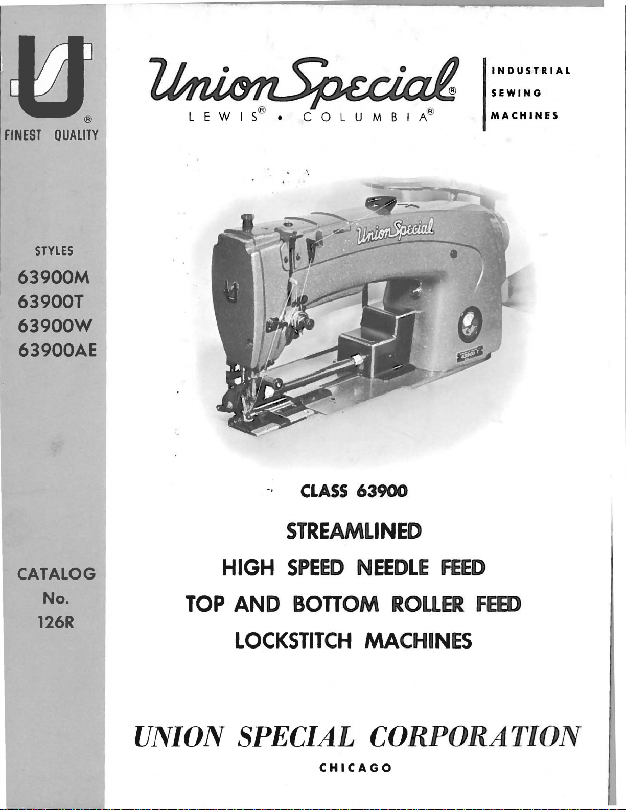
63900M
INDUSTRIAL
From the library of: Superior Sewing Machine & Supply LLC
SEWING
FINEST
QUAliTY
STYLES
63900M
639001
63900W
63900AE
C 0 L U M B I A®
'·
MACHINES
CATALOG
No.
126R
··
CLASS
STREAMLINED
HIGH
TOP
AND
SPEED
BOTTOM
LOCKSTITCH
UNION SPECIAL
CHICAGO
63900
NEEDLE
ROLLER
FEED
FEED
MACHINES
CORPORATION
Catalog
From the library of: Superior Sewing Machine & Supply LLC
INSTRUCTIONS
No.
FOR
126
R
ADJUSTING
LIST
Needle
Top
and
63900
63900
CLASS
Feed
Bottom
Styles
M
w
First
AND
OF
Edition
OPERATING
PARTS
63900
Lockstitch
R.oller
63900
63900
Feed
T
AE
Rights
Union
Reserved
Copyright
By
Special
1966
Corporation
in
All
Countries
UNION SPECIAL CORPORATION
INDUSTRIAl
Printed
SEWING
CHICAGO
in
2
MACHINES
U.S.A.
Reprinted in 4/92
The
From the library of: Superior Sewing Machine & Supply LLC
predom-inant
machines
machines
gauges
1.
2.
insu:r;-ing
A
few
QUICK
The
average
box
to
STREAMLINED
idea
behind~®
in
the
world.
are a decidedachievement
complete
of
the
outstanding
INSTALLATION
installation
production
The
interchangeability.
sewing,
DESIGN
new
features
time
if
FOREWORD
high
installation
spe.ed,
along
are:
required
is
to
streamlined
these
lines.
will
be
instructions
build
Parts
about
the
Class
10
are
best
industrial
63900
are
made
minutes
followed.
lockstitch
to
precision
from
sewing
packing
Pleasing
gedness
is
more·
3.
SIMPLIFIED
Lubrication
for
trouble
system
reservoir,
ance.
4.
RAPID
Precision
oiling
higher
5.
FEED
Machines
the
stitch
It
is
which
SPECIALmachines.The
enables
in
appearance,
and
freedom
restful
OILING
of
these
free
provides
sealed
ACCELERATION
methods
system,
productive
REGULATING
are
fitted
length,
the
constant
customers
this
from
to
the
operator's
machines
operation.
long
hook
against
in
the
makes
plus a readily
aim
possible
rates
and
GEARS
with
feed
of
Union
to
procure
following
functional
difficult-to-clean
eye.
is
automatic.
A
completely
life.
lint
manufacture
lower
A
and
dust,
top
costs.
regulating
accessible
Special
all
pages
discuss
design
single,
reduces
of
operating
gears
to
furnish
possible
provides
recesses.
Oil
is
adjustable,
large
to a minimum
all
parts,
speed
for
means
advantages
valuable
for
concisely
greater
New
supplied
double
capacity,
coupled
almost
quick
Adjusting
and
adjusting
from
stability,
neutral
to
all
filtered
accurately
oiling
with
instantaneous
easy
prepared
the
the
and
Operating
adjustment
taupe
moving
hook
gauged
mainten-
an
advanced
needle
information
use
of
UNION
rug-
finish
parts
oiling
for
of
feed.
data.
Adjusting
call
attention
Illustrations
Exploded
name»
are
requirements.
follow
Union
anxious
Instructions
to
are
views,
the
Special
to
cooperate
for
many
used
Instructions.
representatives,
parts
to
pinpoint
together
in
Mechanics,
which
areas
with
to
planning
covering
must
explanations
be
under
and
meet
found
making
discussion.
in
Styles
exacting
as
to
all
leading
estimates
UNION SPECIAL CORPORATION
3
63900
conditional
quantity,
manufacturing
tailored
M,
T, W and
adjustments.
part
number
to
centers»
meet
AE»
and
your

IDENTIFICATION OF
From the library of: Superior Sewing Machine & Supply LLC
MACHINES
Each
stamped
standard
fixed,
Style
standard
"Style
Styies
number
Example: "63900".
This
listed
of
machines
back,
chine.
High
Light,
Horizontal
Adjusting
Automatic
Needle
Timing
Speed
UNION
into
and
but
never
numbers
machine,
63900
which
catalog
herein.
etc.,
Operating
Streamlined
Medium
Hook
Needle
Lubricating
Bearings
on
Upper
the
special.
contain
MZ".
of
differs
in
are
and
SPECIAL
name
contain
a
"Z"
machines
applies
It
can
this
given
direction
Heavy
Shaft,
Feed,
for
Shaft,
Class.
Take-up
machine
plate
Standard
the
from
also
from
Long
Gears
1
System,
Maximum Work
on
the
letter
letter
is
suffixed
similar
the
style
APPLICATION OF
specifically
be
Reference
the
of
STYLES
Arm
Duty,
1/4
Continuous
for
Inch
Head
Lever
is
identified
the
machine.
Style
"Z".
"Z".
to
in
construction
number,
applied
operator's
handwheel
OF
Needle
Changing
Needle
Oil
and
Space
Style
numbers
Example:
When
the
to
with
to
MACHINES
Feed
Siphon,
Needle
only
Standard
in
CATALOG
the
discretion
direction,
position
is
toward
Lockstitch
Running
Stitch
Bar
Travel,
Bar
to
Right
by a Style
numbers
have
Standard
one
"Style
minor
Style
are
grouped
that
Adjustable
it
such
while
the
Roller
Length,
One
Driving
of
Needle
number
are
or
more
63900
changes
number.
under
contains
Styles
to
some
as
right,
seated
operator.
Machines.
Feed,
Slotted
Reservoir
Hook
Link,
Bar 8 Inches.
which
classified
letters
M".
are
made
Example:
a
class
no
letter.
of
machines
Special
left,
at
the
One
Rotary
Segment
Enclosed
Oil
Control,
Needle
is
as
suf-
Special
in
Styles
front,
ma-
Needle,
Hook,
for
Feed
a
as
63900 M For
alls
of
hem . Maximum
63900 T For
men's
reaches
mum
recommended
63900 W For
to
sew
cation
63900
the
number,
measured
size
needles
recommended
are
AE
foot
Each
kind
number
Needle
listed
Same
of
stamped
in
packaged
making
and
dungarees.
making a 1/2
dress
over
301-SSa-1.
in
needle
below
pants,
machine
topstitching
belt
as
line
shank,
on
thousandths
represent
Type
for
Styles
3/8
recommended
inside
speed
loops.
Style
with
has
both
point,
the
and
sold
180
GVS
and
on
to
1/2
Seam
to 2 1/2
semi-dress
out.
5200
waistbands
Maximum
63900
centerline
a
type
length,
needle
of
an
the
complete
by
is
recommended
63900
the
next
inch
Specification
Fitted
W,
shank,
inch
UNION
T, W and
turned
speed
inch
pants
Seam
R.P.M.
on
with
recommended
except
of
needle
NEEDLES
and
groove,
across
symbol,
SPECIAL.
page.
down
301-EFb-1
5200
hem
Specification
twill
fitted
size
denotes
AE.
and
cloth
number.
finish
the
which
for
The
R.P.M.
turned
work
speed
hole.
Style
hem
by
pants.
and
woolen
plate
5200
with
The
and
the
largest
eye.
is
63900
descriptions
on
legs
inverted.
hand
301-EFb-1
extension.
spring
other
Collectively,
given
on
Sewn
pants.
R.P.M.
guide
type
diameter
on
M
and
of
overalls,
children's
when
or
number
details.
the
Type
and
Specify
garment
EFa-1.
Machine
Seam
keel
sizes
denotes
of
the
label
180
on
The
the
cover-
size
wear,
Maxi-
equipped
Specifi-
presser
size
blade,
type
available
of
GWS
and
all
is
Type
180
No.
GVS
Round
1/16
struck
125/049, 140/054,
shank,
inch
groove,
round
longer
than
deep
point,
standard,
spot,
150/060.
Description
lockstitch,
oversized
chromium
short
plated-
4
ball
length,
eye,
sizes
long
single
100/040,
blade,
groove,
110/044,
NEEDLES
From the library of: Superior Sewing Machine & Supply LLC
(Continued)
Type
180
No.
GWS
To
needle.
complete
Selection
used.
stitch
formation.
The
size
of
the
size
The
of
thread.
above.
than
the
Round
single
100/040.
have
needle
or
the
order
of
Thread
strength
the
thread
of
the
following
The
which
size
specified.
shank,
groove,
orders
type
and
would
proper
should
requirement
used.
needle
table
choice,
may
dictate
round
struck
110/044,
125/049.
promptly
size
number
read: 111000
needle
pass
size
freely
SELECTION
of
The
quality
employed.
shows
the
however.
the
selection
point,
groove.
and
should
Needles,
should
through
OF
PROPER
the
seam
of
preferred
should
Description
lockstitch,
deep
spot,
140/054.
accurately
be
forwarded.
Typz
be
determined
the
needle
NEEDLE
produced
the
work
size
give
consideration
of a needle
short
chromium
filled,
180
GVS.
eye
is
desired
of
needle
size
length,
plated-
an
empty
Use
description
Size
by
the
in
order
SIZE
largely
is
largely
for a given
to
slightly
oversize
sizes
ball
090/036,
package, a sample
on
label.
125/049
size
to
dependent
11
•
of
the
thread
produce a good
upon
dependent
size
and
factors
larger
referred
or
smaller
eye,
A
the
upon
kind
to
Where
Parts
which
Part
appear.
Cotton
the
too
small
distinguish
numbers
Thread
Size
0
30
36
40
50
60
70
80
90
100
construction
for a complete
one
part
represent
Mercerized
IDENTIFYING
permits,
catalog
from
the
another
same
Size
00-
000
0000
0000
each
stamping
that
part,
Thread
B
A
A
0
PARTS
part
is
are
is
similar
regardless
150/060
140/054
125/049
110/044
110/044
100/040
090/036
080/032
080/032
075/029
stamped
identified
in
appearance.
of
Needle
Size
with
the
to
150/060
to
140/054
to
125/049
~
125/049
to
110/044
to
100/040
to
090/036
to
090/036
to
080/032
its
by
catalog
part
letter
in
number.
symbols
which
they
IMPORT
OF
MACHINE
ANT!
FOR
ON
ALL
WHICH
ORDERS,
PART
IS
PLEASE
ORDERED.
INCLUDE
5
PART
NAME
AND
STYLE
ILLUSTRATIONS
From the library of: Superior Sewing Machine & Supply LLC
The
arrangement
ordering
of
Class
of
63900
ORDERING
this
catalog
replacement
OF
REPAIR
is
to
parts.
PARTS
facilitate
easy
and
accurate
Eight
catalog.
ed
as
in
ened
area
machine.
of
the
pieces
exploded
Each
their
exactly
On
parts
required
Numbers
indicate
should
ed
in
number
never
the
for
the
second
each
Sub-assemblies,
a
bracket
or
sub-assemblies,
denting
bly.
18
19
ed
by
tion.
the
sary,
their
Example:
29126
22894
In
those
this
However,
specific
the
EL
J
catalog,
difference
view
plate
assembled
where
the
page
with
in
in
the
their
the
first
position
be
used
column.
part
a
solid
which
descriptions
Needle
Rod
Set
cases
where
no
when
u~age
will
plates
presents
position.
the
opposite
part
particular
column
of
the
in
ordering
Each
for
sale.
which
line
can
box
be
Feed
are
under
cover
a
sector
parts
the
numbers,
are
part
parts.
exploded
sold
on
the
furnished
the
Driving
the
of
Small
being
discussed
illustration
descriptions
view
being
reference
in
the
view
complete
picture
for
description
Eccentric
Standard
the
machine,
keyline
will
shown.
numbers
illustration.
Always
use
plate
or
by
plate.
repairs,
of
and
Styles
views
fit
in
be
and
the
carries
separate
Component
are
the
Connecting
Assembly----------------------------------------
Screw-----------------------------------------
a
specific
the
be
will
part
parts
mentioned
be
is
usage
for
shown
common
will
the
various
in
in
the
to
all
be
mentioned
the
description,
illustration.
of
the
machines
listed
parts
show
being
by a black-
the
assembled
found
the
number
only,
and
Reference
part
number
a
reference
part,
indicated
main
sub-assem-
machines
in
the
are
not
and,
in
a
listing
of
merely
numbers
are
parts
by
cover-
descrip-
the
if
neces-
this
align-
list-
in
of
in-
1
2
same,
At
the
parts
and
shown
description
Success
genuine
UNION
Corporation,
signed
with
according
utmost
Prices
All
shipments
are
insured
postage
and
back
in
of
this
when
in
the
SPECIAL
its
subsidiaries
to
precision.
are
strictly
are
forwarded
unless
otherwise
insurance.
the
book
book.
only
the
USE
operation
repair
the
most
Maximum
net
will
This
will
part
GENUINE
of
these
parts
and
approved
efficiency
TERMS
cash
f.o.b.
directed.
be
found
facilitate
number
REPAIR
machines
as
furnished
authorized
scientific
and
subject
shipping
A
6
a
numerical
is
known.
PARTS
distributors.
and
durability
to
point.
charge
locating
can
be
by
the
principles,
change
Parcel
is
made
index
the
secured
Union
They
are
without
Post
to
cover
of
all
the
illustration
only
with
Special
are
and
are
made
assured.
notice.
shipments
the
de-

UNPACKING
From the library of: Superior Sewing Machine & Supply LLC
CAUTION!
Using
packed.
steps
STANDARD
eyelet,
base
(1)
extension
pivot
for
both
Before
After
should
Included
(1)
plate,
can
of
Included
Included
Included
brackets,
pivot
oil
and
pin
When
unpacking,
hands
screw
(1)
on
bed
leaving
be
ACCESSORIES
with
and
also
also
also
and
the
machine
followed:
each
for
knee
(1)
with
with
(3)
screws
with
(1)
(1)
the
upper
press
extra
Style
folder
rock
casting,
factory,
and
machine
frame
rod,
bobbin.
Style
Styles
for
actuator
shaft
DO
lift
each
accessories
is a box
eyelet,
(1)
bobbin
63900 T is
63900 W and
cloth
plate
63900 M is
finger,
connecting
NOT
gently.
Union
(1)
winder
(1)
extension.
(1)
(1)
of
front
arm.
INSTALLING
lift
m?.chine
Special
have
standard
base
bell
63
900
pivot
machine
been
plate,
assembly,
crank
AE
is
pivot
bracket,
pin
out
of
box
removed
accessories
(1)
hook
(2)
actuator
(1)
bell
for
folder
is
sewed
from
screws
rod.
crank
(1)
actuator
by
oil
rear
placing
off,
the
packing
--
containing
return
for
actuator
pivot
finger,
one
hand
inspected
channel,
bobbin
rod,
bracket,
box,
(1)
winder
(2)
retaining
on
handwheel.
and
the
upper
(3)
screws
asserpbly,
(1)
cloth
(2)
screws
carefully
following
frame
for
plate
for
rings
650
21661
==:~
These
AC
and
-36
~:
p..:.._
are
(4
*
___
parts
not
Fig.
'
are
components
furnished
1
with
of
1400 D pedestal
the
machine.
660-168
Cushion
69
FD
664
Screw*
J
7

PREPARATION
From the library of: Superior Sewing Machine & Supply LLC
Before
machine.
Style
and
21662
the
bottom.
pin
(21664
base
plate
hook
oil
to
hold
Styles
{21680
(63996)
used
to
NOTE:
the
machine
machine
The
63900 M {Fig.
AE)
Now
J).
now
return
the
base
63900
AX)
to
is
mounted
hold
the
Cloth
is
PREPARATION
The
pedestal
the
hemmer,
be
accomplished
The
pedestal
knee
final
press
adjustment
assembly
al.
the
ment
the
for
Place
pedestal
On
"S"
lifting
of
the
the
Style
hook
the
so
knee
to
OF
machine
on
top
assemble
Snap
can
channel
plate
T,
the
bottom
base
plate
set
OF
for
in
the
after
for
of
four
the
press
63900
the
presser
MACHINE
can
be
also
1)
of
the
retaining
be
assembled
{63996)
to
the
63900
of
under
the
plate.
extension
on
the
pedestal,
PEDESTAL
Style
left
hole
the
machine
Styles
for
lifting
the
knee
isolators
four
holes
assemblies
M, a
treadle
chain
hook
foot
INSTALLING
FOR
INSTALLATION
placed
has
is
folder
to
prepared
base
rings
is
onto
be
prepared,
plate
actuator
{660-254
to
the
under
machine.
Wand
63900
machine,
base
Attach
using
plate
upper
{63982
using
FOR
INSTALLATION
63900 M {Fig.
of
the
pedestal.
has
63900
press
the
assembly
{51295
in
base
T,
63900
presser
B)
can
and
chain
on
the
underside
can
also
be
the
pedestal,
by
mounting
(21680
AX),
finger
D)
machine~
the
base
AE
{Fig.
three
and
is
held
frame
E)
three
1)
can
screws
is
prepared
eyelet
Final
been
placed
Wand
foot,
will
be
in
the
recesses
plate
align
now
be
made.
is
required
used
for
Styles
(Continued)
the
prior
to
the
using
{21665 H)
onto
using
plate
2)
are
screws
in
be
mounted
adjustment
on
the
63900
in
the
after
with
the
of
bed
63900
pedestal
being
front
two
between
the
pivot
three
and
is
prepared
(22652
position
(A,
Fig.
{22517
by
mounting
pedestal.
AE
left
hole
the
machine
of
the
pins
to
lift
plate
T,
has
to
placed
and
rear
screws
the
pin
and
screws
attached,
by
merely
D-8).
by
the
3)
using
on Sty
le
B).
the
of
the
{Fig.
of
2)
the
has
pedestal.
in
the
the
presser
at
the
back.
63900 W and
be
prepared
on
the
pedestal.
pivot
{22517
two
brackets
B)
brackets,
locate
(22652
using
D-8),
the
mounting
The
hook
left
hand
screw
screw
(22570
63900 W and
knee
press
knee
press
is
prepared
pedestal.
been
placed
Now
place
isolators.
foot
and
The
treadle
63900
coming
in
being
left
oil
return
63900
assembly
by
Once
on
the
The
roller.
AE,
to
receive
(21662
up
using
grooves.
sure
screw
the
base
marked
A).
AE
for
collapsing
mounting
again,
the
machine
final
mechanism
if
desired.
the
AF
from
pivot
The
the
used
plate
channel
"X"
after
will
the
the
pedest-
on
adjust-
Attach
~'
These
parts
and are
8
not
are
components
furnished
with
of
1400 D pedestal
the
machine.
Fig.
2
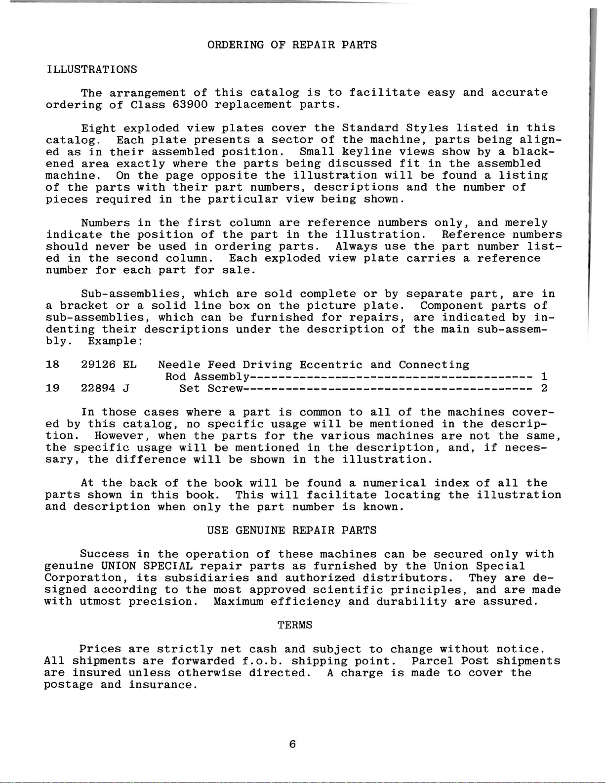
TABU::BOAI~D
From the library of: Superior Sewing Machine & Supply LLC
The
so
the
The
of
has
from
"Winding
These
tableboard
top
of
\\'INDEH
bobbin
the
sewint;
two
the
belt
against
machines
nuts
BOBBIN
front
winder
away
pressure
under
BELTS
can
the
tableboard
winder
machine
elongated
as
the
beLt
The
Bobbin",
are
now
be
should
attaching
needed,
to
wind
equipped
mounted
is
be
belt
The
the
under
to
INSTALLING
on
flush
with
secured
and
\\ill
holes,
pulley
bobbin.
"Instructions
use
either
the
pedestal
the
to
the
bear
\\
hich
of
the
Hegulation
Il l
(Continued)
top
of
table
against
allo\\'
\\'indcr,
For
Operators".
"Vee"
using l'our
the
machine
top
so
that
the
belt
the
mechanism
\\he-n
and
operation
or
round
screws
b0d
its
when
in
operation,
belts.
(650
plate.
pulley
in
to
be
of
the
AC-36),
will b Located
operation.
moved
should
bobbin
FROM CONE
The
closer
exert
winder
adJusting
directly
base
to
or
farther
only
enough
is
described
of
the
in
the
Fig.
3
9

LUBRICATION
From the library of: Superior Sewing Machine & Supply LLC
CAUTION!
the
reservoir
Lubricate
and
speed
run
slowly
operation
must
machine
RECOMMENDED
Use a stainless
125
seconds
Special
check
marked
_
It
an
extended
oil
the
Replace
Oil
OIL
GAUGE
The
Should
oil
is
an
at
specification
level
"FULL".
recommended
period,
bearings
end
cover,
may
oil
be
gauge
adjustment
Oil
has
be
for
several
can
then
OIL
water-white
100°
at
gauge
Oil
of
the
as
drained
is
set
been
filled
before
thoroughly,
minutes
be
expected
Fahrenheit
No.
175.
(C):
should
be
that a new
be
lubricated
needle
no
further
from
at
the
become
drained
straight
in
the
Fill
oil
is
at
added
machine,
as
bar
hand
main
factory
necessary,
from
starting
in
accordance
to
distribute
without
mineral
main
main
reservoir
maximum
when
follows:
link,
the
oiling
reservoir
to
show
the
main
to
operate.
the
damage.
oil
reservoir.
level
needle
or
one
Remove
take-up
will
be
by
removing
the
the
following
reservoir
with
instructions
oil
to
of a Saybolt
This
at
plug
when
is
in
yellow
that
has
the
and
required.
proper
oil
steps
the
is
screw
needle
band
been
head
its
lever
plug
level
before
which
various
viscosity
equivalent
(B,
is
in
marked
out
of
cover
and
screw
in
the
should
shipment
follow,
parts.
of
to
Fig.
3)
yellow
"LOW".
service
and
directly
needle
(D,
Fig.
reservoir.
be
followed:
and
Full
90
to
Union
and
band
for
bar.
3 ).
1.
2.
3.
4.
5.
Place
Remove
bottom
Oil
should
below
Loosen
right
so
Tighten
the
the
of
the
lock
the
lock
machine
reservoir
the
machine).
be
added
bottom
nut
(E,
gauge
nut
upright
edge
needle
and
plug
or
removed
of
the
Fig.
3)
replace
on a level
screw
hole.
on
the
rests
on
plug
table
(located
so
that
calibrating
the
yellow
screw.
the
or
below
oil
band
bench.
level
screw
marked
the
handwheel
is
approximately
(F),
and
"FULL".
turn
and
screw
on
gauge
near
1/8
left
the
inch
or
(C).
10
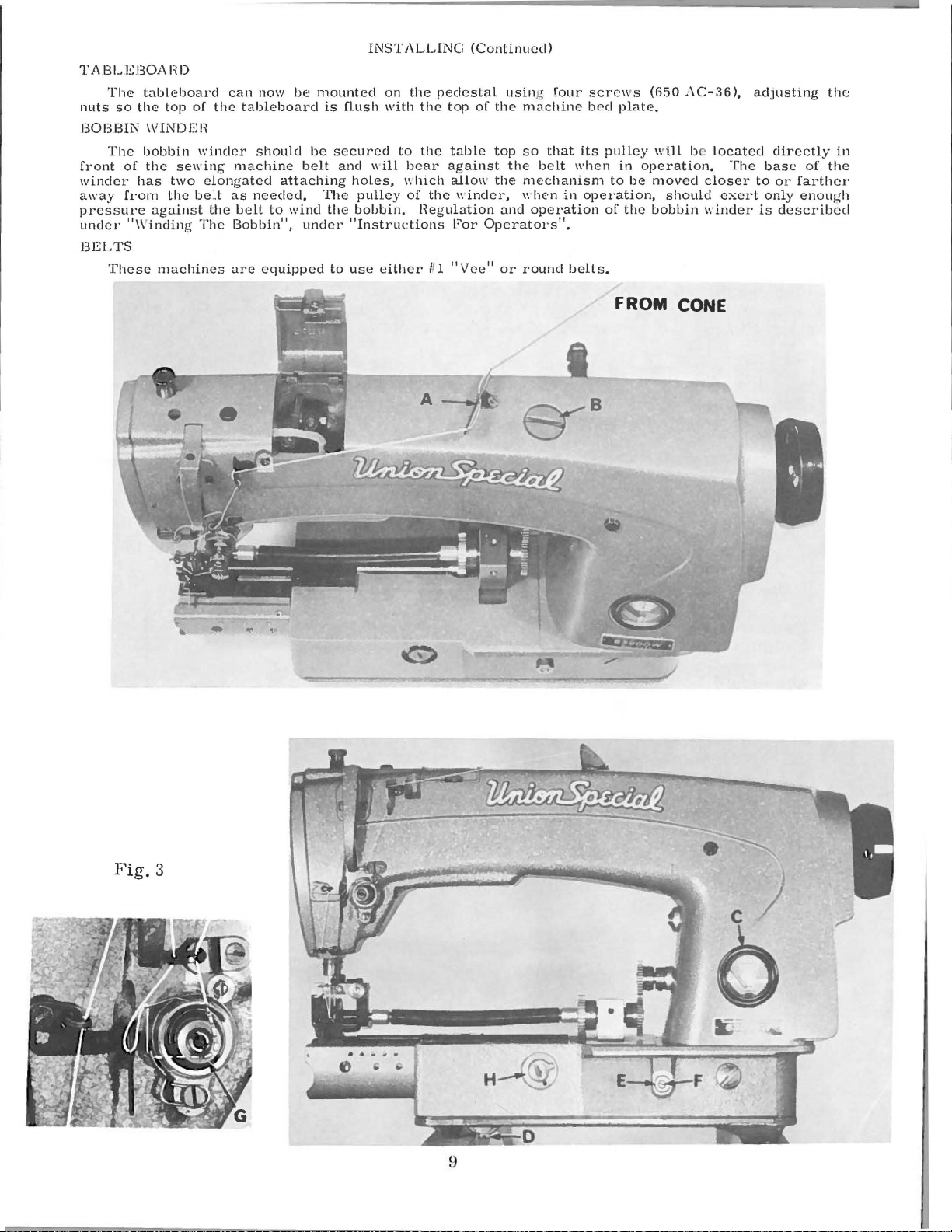
SELF-PRIMING
From the library of: Superior Sewing Machine & Supply LLC
HEAD
OIL
SIPHON
Class
the
machine
and
trickles
established,
twenty-four
which,
61494
Screw
of
L
--------------~~~~~
63900
is
started,
down
it
is
machines
the
maintained,
hours a day,
course,
far
are
oil
splashes
vertical
removing
exceeds
equipped
on
oil
tube,
unless
oil
the
rate
with a self-priming
the
thus
the
at
at
priming
priming
felt
the
which
rate
cup
is
removed.
of
six
oil
collects
the
felt,
siphon.
to
twelve
head
filters
The
in
the
oil
siphon.
through
Once
siphon
drops
head.
the
per
61494
When
the
felt
prime
operates
minute,
N
6:l994
OilS
phon
is
8
A
newly
machine
is
removed
should
function,
felt
block
do
not
The
666-237,
felt
also
If
the
an
excessive
cup
felt
666-23
be
installed
However,
the
siphon
from
oil.
cup.
In
trapping
INSTALLING
installed
is
operating.
from
be a distinct
determine
and
that
correct
felt
is
acts
the
in
the
to
meter
as a filter
priming
amount
is
replaced
7.
For
the
dry.
if
for
may
fail
Then,
other
of
words,
air,
the
line
reduction
if
the
siphon,
priming
the
cup
of
by
best
The
some
because
while
squeeze
and
siphon
However,
and
the
siphon
plastic
replace
flow
and
felt
and
lint,
removing
initial
intake
reason
squeezing
no
trouble
AND
MAINTENANCE
starts
it
the
siphon
of
the
intake
tube
is
the
cup
is
of
priming
keeps
it
the
may
the
intake
access
self-priming
felt
is
the
air
is
trapped
the
out
the
should
its
action
may
be
is
oil
in
tube,
connected
siphon
designed
oil
siphon
felt
be
necessary
plug
replaced
priming
felt
between
air
and
be
OF
within
twenty
in
full
the
minutes
operation.
head
located
at
both
felts
as
for a specific
and
to
prevent
clear
of
(666-214)
to
at
back
condition,
by
removing
cup
felt
in
the
felt.
the
replace
experienced
OIL
SIPHON
three
to
or
five
so
Within
sump.
in
ends.
described
the
If
the
head,
If
the
below.
purpose.
the
entrance
lint.
becomes
replace
of
the
has
the
machine
felt
the
been
oiled
felts.
of
end
As a precaution,
fingers,
it
with
when
saturate
oil.
starting
minutes
before
an
siphon
is
inserted
above
This
after
all
hour,
does
two
felt»
of
air.
contaminated
The
priming
and
replacing
the
siphon
cover.
before
installing,
remove
it
well
This
prevents
the
siphon.
the
the
air
there
not
in
the
items
No.
The
with
felt
should
felt
with
the
11

THREAD
From the library of: Superior Sewing Machine & Supply LLC
INSTRUCTIONS
FOR
OPERATORS
While
of
the
the
direction
of
each
WINDING
Thread
from
down
post.
(B).
bobbin a few
downwardly
into
position.
will
automatic
pulley.
be
between
up
contact
be
varied
hook
hand.
Fig.
the
Press
to
rotated
The
the
THE
supply
the
When
throw-out
by
direction
rotation
of
twist.
Turn
5
BOBBIN
the
bobbin
down
the
tension
an
empty
stop.
turns
on
with
extent
regulating
in a clockwise
hand
machine
the
and
of
the
favors
grasp a short
the
thread
unwind.
REMOVING
direction
the
machine.
the
the
be
winder
through
discs.
bobbin
wind
lever
machine
filled
member.
to
the
belt,
until
which
the
twist
the
use
away
To
remove
left
hand,
bobbin
Opening
latch
removed.
by
the
and
on
end
direction
(D)
until
and
is
operated.
the
which
the
bobbin
screw
in
the
of a left
length
from
it
is a left
THE
until
open
case
the
is
closed.
leading
eyelet
under
the
of
thread
pulley
is
locked
thread
disengages
(C).
bobbin
twist
of
you
BOBBIN
the
bobbin
needle
reach
the
bobbin
out
latch
the
(A,
the
winder
and
is
the
engages
is
filled
thread
thread
thread
with
twist.
case.
reaches
in
under
of
the
retains
the
bobbin
thread
Fig. 6 ).
tension
shaft
around
press
moved
in
that
bobbin
the
the
can
is
in
between
your
if
not.
CASE
turn
its
the
case
sewing
the
is
immaterial.
the
needle.
thumb
right
latch
hand.
it
handwheel
highest
throat
(A.
hook.
bobbin
released
is a right
plate
and
If
position.
Fig.
in
the
and
the
direction
To
determine
forefinger
the
in
operating
at
left
5).
case.
can
strands
twist.
Using
end
and
pull
When
readily
of
The
base.
ing
wind
all
and
machine
and
screw
unevenly
The
times.
begin
tension
can
purpose
is
be
(E)
so
may
When
to
wind
sewing.
Fig.
post
shifted
that
of
the
7
bracket
be
readily
the
bobbin
the
from
any
tendancy
bobbin
empty
is
mounted
left
to
right
of
corrected.
winder
in
the
machine
one
immediately.
THREADING
The
the
thumb,
hand.
The
thumb
coming
on
the
by
the
is
to
bobbin
forefinger
bobbin
and
forefinger
off
the
12
winder
loosen-
bobbin
assure
is
used
THE
case
(B)
bottom
to
up.
Bobbins
BOBBIN
(A.
itself
an
replace
Fig.
and
of
of
the
operator
can
be
CASE
7)
should
second
should
the
right
bobbin.
Fig.
of a full
it
with
rewound
be
finger
be
held
hand
6
bobbin
the
full
while
held
between
of
the
between
with
at
one.
the
LEFT
the
thread

INSTRUCTIONS
From the library of: Superior Sewing Machine & Supply LLC
FOR
OPERATORS
(Continued)
THREADING
Place
finger
Fig.
8)
direction
at
the
the
of
right
under
of
bobbin
Fig.
the
handwheel.
The
cross
(A,
Fig.
as
far
mulated
as
lint
9 )1 is
it
THE
bobbin
hand~
the
the
case
8
hole
will
from
BOBBIN
in
draw
tension
rotation
from
REPLACING
and
latch
the
be
be
INSERTING
with
Tighten
in
to
show
go
and
1
needle
CASE
bobbin
the
spring
of
the
the
Have
one
should
throat
placed
released
Insert
the
set
the
needle
the
to
(Continued)
case.
bobbin
bobbin
back.
the
half
plate
part
the
spot
screw
In
one
thread
(B)
and
as
The
bobbin
THE
BOBBIN
needle
inches
be
opened
and
way
and
bobbin
THE
NEEDLE
needle
(sometimes
securely.
into
the
bar
through
into
bar1 about
operator
when
provide a means
hole
so
the
needle
continuous
through
self
threading
end
of
should
CASE
at
its
of
thread
with
the
the
sewing
case
into
the
called
1/4
needle
for
will
motion1 with
diagonal
the
thread
rotate
highest
to
hang
left
hand1 and
the
bed
hook.
snapped
needle
scarf)
inch
from
has
been
cleaning
seat
thumb
slot
in
bobbin
slot
(C)
on
is
pulled
when
counterclockwise.
position1 allow
free.
plate
into
bar
toward
the
The
position.
The
by
reaching
extension~
latch
as
far
the
right1 facing
end
inserted
the
accu-
properly.
and
case.
about
bobbin
it
should
as
it
A
fore-
case
Note
looking
two
case
under
should
then
will
(A
go
1
1
THREADING
Threading
thread
the
passes.
needle
eye
PREPARATION
With
the
handwheel
highest
it,
through
your
position.
the
foot.
--.: •
..,,~
Fig.
tension
bobbin
this
adjustment
1 0
on
the
suspended
THE
NEEDLE
diagram
Please
from
left
FOR
left
hand1 hold
in
operating
Pull
needle
TENSIONS
B A
.,.
thread
sewn.
on
BOBBIN
screw
spring
by
check.
(Fig.
note
to
right.
SEWING
direction
up
the
hole
in
perfect
are
A
both
threads.
THREAD
The
tension
(A,
is
correct
the
bobbin
3)
that
the
needle
the
locked
stitch
Fig.
when
shows
the
end
of
until
thread
throat
stitch
of
this
TENSION
on
10)
it
thread.
the
places
needle
the
needle
the
and
plate.
is
one
together
kind
the
bobbin
which
is
just
The
where
thread
passes
thread1 leaving
needle
Draw
in
in
is
the
bobbin
both
which
the
secured
moves
center
case
regulates
sufficient
thread
should
the
threads
the
is
applied
the
to
needle
through
down
thread
needle
of
by
regulating
tension
hold
not
it
slack1 and
and
will
under
thread
the
material
by
spring
the
bobbin
be
in
Fig.
up
again
come
the
and
the
means
the
eyelet
9
turn
to
up
with
presser
bobbin
being
tensions
of a set
(B).
The
case
its
and
for
13
INSTRUCTIONS
From the library of: Superior Sewing Machine & Supply LLC
FOR
OPERATORS
(Continued)
BOBBIN
THREAD
Remove
turn
set
to
apply
release
When
rarely
as
varying
screw
more
tension.
the
becomes
attain a good
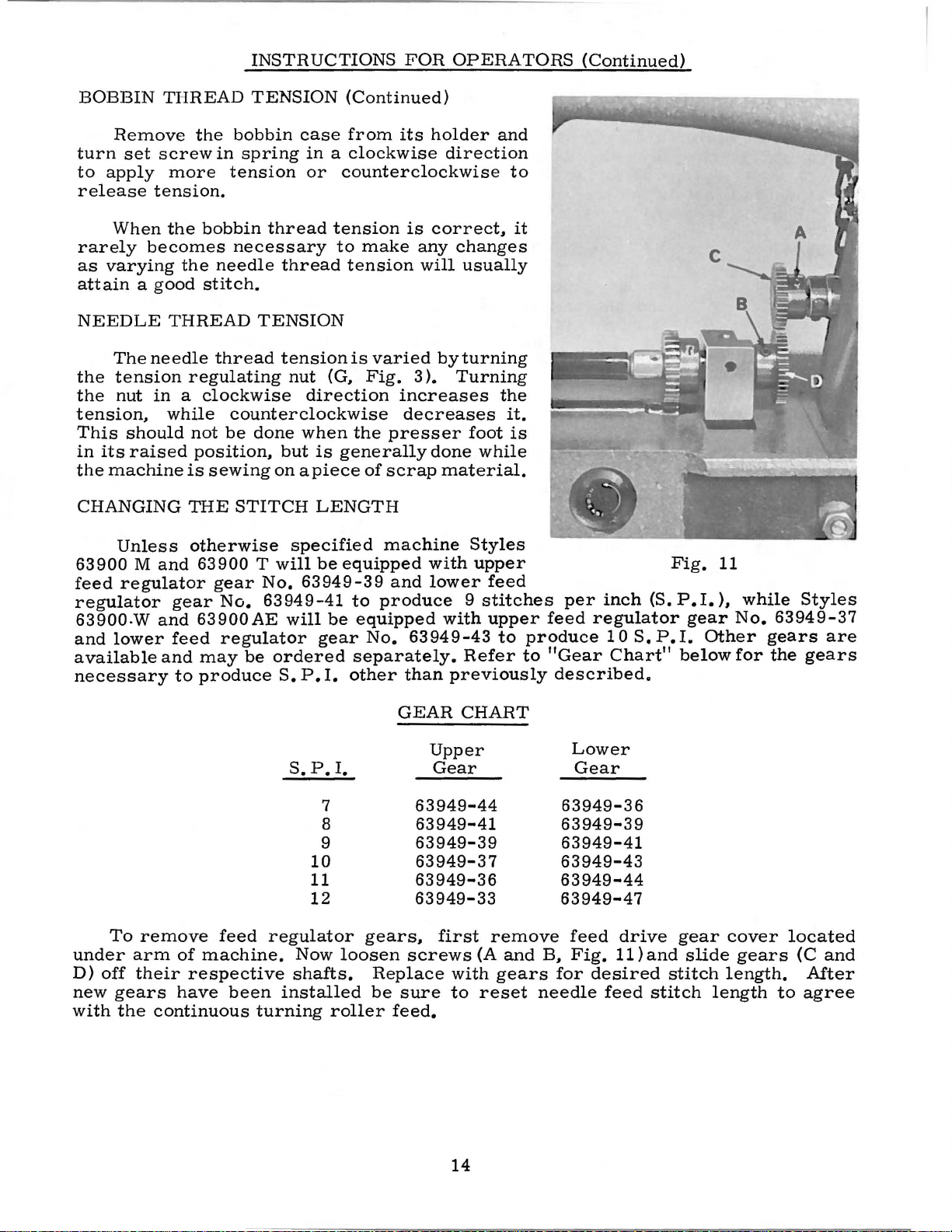
NEEDLE
The
the
tension
the
nut
tension,
This
in
its
the
machine
THREAD
needle
in a clockwise
while
should
raised
CHANGING
Unless
63900 M and
feed
regulator
regulator
63900.W
and
lower
available
necessary
gear
and
feed
and
to
the
bobbin
in
spring
tension
bobbin
necessary
the
needle
stitch.
thread
regulating
counterclockwise
not
be
position,
is
sewing
THE
STITCH
otherwise
63900
gear
No.
63900AE
regulator
may
be
produce
TENSION
case
in a clockwise
or
thread
thread
TENSION
tensionis
nut
(G,
direction
done
but
on
when
is
apiece
LENGTH
specified
Twill
No.
be
63949-39
63949-41
will
be
gear
ordered
S.
P.
I.
(Continued)
from
its
holder
direction
counterclockwise
tension
to
tension
make
varied
Fig.
is
correct,
any
will
byturning
3 ).
changes
Turning
increases
decreases
the
presser
generally
of
scrap
done
material.
machine
equipped
to
produce 9 stitches
equipped
No.
with
and
lower
63949-43
with
separately.
other
than
previously
and
to
usually
the
it.
foot
is
while
Styles
upper
feed
upper
to
Refer
it
feed
produce
to
"Gear
described.
per
regulator
inch
10
S.
Chart"
(S.
P.
. • •
..
" . \
~-"· . ~
~
.:
Fig.
P.I.
gear
I.
Other
below
11
),
'1,
......
...
---c
while
No.
for
A
:.
•. -·:
~ .·~
,, ,.
.
p
""'~.~
..
~
~a..t
~
..
_1\
.,_,
Styles
63949-37
gears
the
are
gears
•
under
D)
off
new
with
To
remove
arm
their
gears
the
feed
of
machine.
respective
have
been
continuous
S.
P.
10
11
12
regulator
Now
shafts.
installed
turning
I.
7
8
9
loosen
roller
GEAR
63949-44
gears,
screws
Replace
be
sure
feed.
CHART
Upper
Gear
Lower
Gear
63949-36
63949-41
63949-39
63949-39
63949-41
63949-37 63949-43
63949-36
63949-33
first
(A
with
to
reset
remove
and
gears
63949-44
63949-47
feed
B,
Fig.
for
needle
drive
11)and
desired
feed
gear
slide
stitch
stitch
cover
gears
length.
length
located
(C
After
to
agree
and
14
 Loading...