


 Loading...
Automated Systems Division
ARGO 42/A
Comelz
Drive Motor & Stepper Drive
Eprom Version B
Instruction Manual
CATPT9910
Union Special Corporation
Automated Systems Division

ARGO 42/A
INSTALLATION
USE
MAINTENANCE
Eprom B
Catalog Part Number
CATPT9910

COMELZ |
ARGO 42/A |
2 |
|
|
|
INSTALLATION ................................................... |
5 |
CONNECTING TO MAINS ................................................................................... |
5 |
CONNECTION TO THE SEWING MACHINE .................................................. |
5 |
SYNCHRONIZERS / INSTALLATION AND TIMING ..................................... |
5 |
INSTALLATION OF ME100 SYNCHRONIZER.......................................................................... |
5 |
INSTALLATION OF ME200 SYNCHRONIZER.......................................................................... |
6 |
INSTALLATION OF ME300 SYNCHRONIZER.......................................................................... |
6 |
TIMING............................................................................................................................................ |
6 |
“0” reference position without using the MT800 console .................................................... |
6 |
SOCKET PANELS .................................................................................................. |
7 |
CZ0 AND CZ1 SOCKET PANELS................................................................................................. |
7 |
CZ2 SOCKET PANEL..................................................................................................................... |
7 |
CZ3 AND CZ4 SOCKET PANELS................................................................................................. |
7 |
NT4 SOCKET PANEL .................................................................................................................... |
8 |
THE MT800 CONSOLE ......................................................................................... |
8 |
PROTECTED ACCESS TO INFORMATION ..................................................... |
8 |
INSTALLATION SETUP ....................................................................................... |
8 |
TRANSFER OF THE SETUP THROUGH THE KK195 MEMORY ............................................ |
8 |
SELECTION AMONG CONFIGURATIONS INCLUDED IN THE “LIBRARY |
|
OF CONFIGURATIONS”.............................................................................................................. |
9 |
SETUP -01 / machine selection ............................................................................................. |
10 |
DIRECT PROGRAMMING OF MOTOR CONFIGURATION................................................... |
10 |
SETUP -02 / machine parameters ........................................................................................ |
10 |
TIMING (DIRECTION OF ROTATION, NEEDLE POSITIONS)................................................... |
11 |
ROTATION (SPEED, ACCELERATION) ....................................................................................... |
11 |
TREADLE ....................................................................................................................................... |
12 |
COVER PAGES ................................................................................................... |
13 |
MOTOR DIAGNOSIS....................................................................................................................... |
13 |
PROTECTED ACCESS SETUP .............................................................................................. |
14 |
SETUP -03 / machine devices................................................................................................ |
14 |
THREAD TRIMMER....................................................................................................................... |
14 |

COMELZ |
ARGO 42/A |
3 |
|
|
|
TENSION RELEASE ....................................................................................................................... |
15 |
THREAD WIPER ............................................................................................................................ |
16 |
PRESSER FOOT LIFTER ............................................................................................................... |
16 |
BACK-TACK ................................................................................................................................... |
16 |
NEEDLE COOLING ....................................................................................................................... |
17 |
CHAIN SUCTION (VENTURI) ....................................................................................................... |
17 |
PHOTOCELL ........................................................................................................................ |
17 |
SAFETY SWITCH ................................................................................................................. |
17 |
STATIONARY BRAKE .................................................................................................................... |
18 |
HP ADLER / JUKI .......................................................................................................................... |
18 |
CUTTER.......................................................................................................................................... |
18 |
STEPPER MOTORS ....................................................................................................................... |
19 |
AUTOMATION ..................................................................................................... |
19 |
SETUP –10 / output signals / input signals........................................................................ |
19 |
PROGRAMMING OUTPUT SIGNALS ....................................................................................... |
19 |
PROGRAMMING INPUT SIGNALS............................................................................................ |
22 |
CONNECTION OF INPUT DEVICES (MICRO-SWITCHES, NPN, PNP)......................................... |
24 |
USE........................................................................ |
26 |
CONSOLES AND KEYBOARDS ........................................................................ |
26 |
MT800 CONSOLE......................................................................................................................... |
26 |
MT600 CONSOLE......................................................................................................................... |
26 |
MT100 AND MT400 KEYBOARDS............................................................................................ |
27 |
MT500 KEYBOARD..................................................................................................................... |
27 |
SEWING PROGRAMMING ................................................................................ |
27 |
STEP PROGRAMMING ............................................................................................................... |
28 |
Operations............................................................................................................................... |
28 |
Sewing mode ........................................................................................................................... |
29 |
Behavior of devices while sewing.......................................................................................... |
29 |
COMELZ |
ARGO 42/A |
4 |
|
|
|
Behavior of devices at the end of the sewing ....................................................................... |
30 |
Beginning and end of a Step and shift from a Step to the next one .................................. |
30 |
USE OF THE PHOTOCELL ......................................................................................................... |
31 |
Additional conditions for the use of the photocell .............................................................. |
32 |
USE OF THE AUTOMATION FUNCTIONS .............................................................................. |
32 |
Importance of the Pause Step ............................................................................................... |
33 |
CREATING A PROGRAM BY SELF-TEACHING .................................................................... |
33 |
PROGRAM MANAGEMENT ...................................................................................................... |
33 |
Modifying and deleting a Program ...................................................................................... |
34 |
Correction of a Program and limitation to correction ....................................................... |
34 |
Transferring a Program ........................................................................................................ |
34 |
PROGRAM 000...................................................................................................... |
35 |
PROGRAM INDEX............................................................................................... |
35 |
PIECE COUNTING / PRODUCTION CONTROL ........................................... |
36 |
USE OF STANDARD COVER PAGES............................................................... |
37 |
MAINTENANCE ................................................. |
39 |
TROUBLESHOOTING ................................................................................................................. |
39 |
ERROR MESSAGES DISPLAYED BY THE MT800 CONSOLE.............................................. |
39 |
COMPLETE MOTOR RESET ...................................................................................................... |
40 |
RUNNING THE MACHINE WITHOUT SYNCHRONIZER...................................................... |
40 |
BUILT-IN BACK-UP MEMORY ................................................................................................. |
40 |
REPLACEMENT OF THE SOCKET PANEL.............................................................................. |
40 |
REPLACEMENT OF THE SYNCHRONIZER ............................................................................ |
41 |
REPLACEMENT OF THE KK66 ELECTRONIC BOARD ........................................................ |
41 |
REPLACEMENT OF THE FRONT PEDAL PANEL .................................................................. |
41 |
MOTOR REPLACEMENT............................................................................................................ |
41 |
SOFTWARE UPDATING ............................................................................................................. |
41 |
EXAMPLES (Sewing Programs)........................ |
42 |
SM1 STEPPER MOTOR DRIVER ………….. 61 |
|
COMELZ |
ARGO 42/A |
5 |
|
|
|
INSTALLATION
CONNECTING TO MAINS
ARGO is a 220 V single-phase unit and it can be immediately connected to the 220 V single-phase line.
It can also be connected to the 380 V three-phase line by obtaining 220V using any one of the three phases and the neutral wire. In case of connection to the 380V three-phase line it is important not to connect the unit between two phases instead of between any one phase and the neutral wire.
By request Argo is available in 110V model.
Also the ground wire must be absolutely connected for correct functioning of the motor (through the mains socket). Besides, near the unit there must not be any equipment that has sparking contacts (as lacking the correct protections). For a good functioning it is necessary to connect the sewing machine head to the ground screw located on the motor housing.
CONNECTION TO THE SEWING MACHINE
The motor is fixed to the stand through a bracket. Fixing holes comply with both DIN and ASA norms.
The transmission of the motion is effected through a V belt, “Z” section. Choose the diameter of the motor pulley (PUL) so as to obtain a correct ratio between the maximum rotation speed allowed on the machine (MAX) and the rated rotation speed of the motor (4500rpm). A different ratio to the motor speed (max. 6000rpm) reduces performances.
The correct pulley size is given to the technician during the configuration process of the motor (page 11). The correct pulley size can also be calculated using the following formula:
 (where DV is the pitch diameter of the hand-wheel of the machine): Pulleys are available with pitch diameters (in mm): 50, 58, 63, 67, 71, 75, 80, 85, 90, 95.
The treadle is connected to the control lever on the main body of ARGO, through the rod (extensible) that is usually fitted to the machine.
To prevent vibrations from moving the motor and loosening the belt, the screws that connect the motor to the bracket must be securely fastened with the wrench provided with the unit.
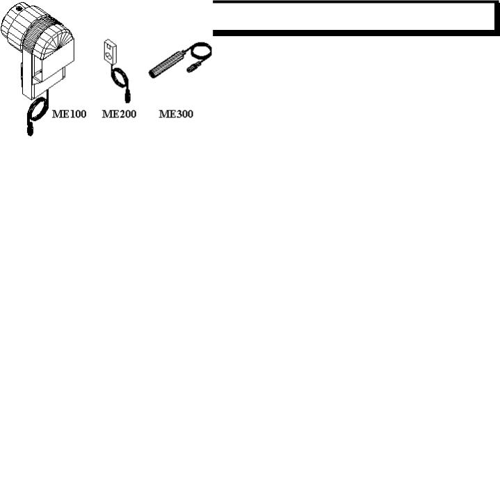
SYNCHRONIZERS / INSTALLATION AND TIMING
Besides the traditional optical synchronizer (ME100), other two synchronizer types are available (miniaturized and without mechanical parts): one Hall-effect based type (ME200) and one with proximity sensor (ME300). These two types satisfy the need to eliminate rotating members inside the synchronizer, especially on fast machines.
INSTALLATION OF ME100 SYNCHRONIZER
Just fit the synchronizer to the shaft. No mechanical adjustment is required, as the setting of the “0” reference and the stopping positions of the machine will be accomplished afterwards in the configuration phase (see Timing paragraph page 11).
COMELZ |
ARGO 42/A |
6 |
|
|
|
INSTALLATION OF ME200 SYNCHRONIZER
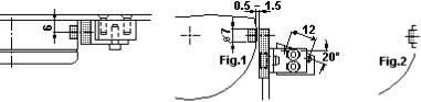
The ME200 synchronizer is a Hall-effect sensor and a permanent magnet.
The magnet has to be fastened to a rotating part of sewing machine, keeping the white side on the outside.
If the magnet is fixed to an aluminum or plastic hand-wheel, the magnet itself can be completely inside the part; if the magnet is fixed to ferrous materials (like steel, cast iron), it must be free at least one half of its height and twice its diameter (picture 2). The sensitive area of the sensor is where the white dot is located.
The sensor must be fixed not further than 1.5 mm (1/16 in) from the magnet, taking care that the white point is facing the white surface of the magnet.
The setting of the “0” reference and the stopping positions of the machine will be accomplished afterwards in the configuration phase (see Timing paragraph page 11).
INSTALLATION OF ME300 SYNCHRONIZER
This synchronizer detects the proximity to metallic parts; it can be used on machines having metal sectors on the plastic handwheel (place it on the sector that gives only one signal per revolution), or on other machines, making the necessary adjustments (only one detection per revolution is necessary).
The proximity sensor must not be further than 1,5 mm (1/16 in) from the hand-wheel.
The setting of the “0” reference and the stopping positions of the machine will be accomplished afterwards in the configuration phase (see Timing paragraph page 11).
TIMING
The timing operation is usually accomplished through the MT800 console as explained in paragraph Timing page 11.
“0” reference position without using the MT800 console
When the MT800 console is not available, the motor being installed must already be fully set-up, so that only the “0” reference position must be defined. This can be achieved through the following procedure:
•Turn the machine on.
•Rotate the hand-wheel by hand for at least 3-4 revolutions.
•Move the needle tip to skim the needle plate (while moving down).
•Heel back the pedal to -2 (trimming position) and turn the motor off (while keeping the treadle at full heeling position).
It must be remembered that in case the KK66 board must be replaced it is necessary to set-up the motor as if it were a new installation.

COMELZ |
ARGO 42/A |
7 |
|
|
|
SOCKET PANELS
Easily interchangeable, their aim is to adapt Argo to the different types of connectors on sewing machines of different brands (AD2 for Adler machines; DK2 for Dürkopp machines; JK2 for Juki machines; PF2 for Pfaff machines; and so on).
For those machines that do not bind to special connectors, it is advised to use the panels of the CZ class (CZ0, CZ1, CZ2, CZ3, CZ4). It is possible to use the CZ class panels also for those sewing machine brands that have very special connectors, by using proper wiring harnesses (available as accessories).
Their performances and number of inputs/outputs change according to the user's different requirements and offer full assistance to the development of automation.
CZ0 AND CZ1 SOCKET PANELS
Choose them when Sewing Programs and photocell are not used.
Three outputs are available on the CZ0 panel: presser foot lifter, thread trimmer (or chain suction on over-lock machines), thread wiper (or tension release, or needle cooling (running signal)). One input for the emergency stop and one duplicate for the synchronizer are also available besides the standard ones for the synchronizer, the console and the keyboard.
Five outputs are available on the CZ1 panel: presser foot lifter, thread trimmer (or chain suction on over-lock machines), tension release (or needle cooling (running signal)), thread wiper, reverse feed (back-tack) or upper thread trimmer. Besides the standard inputs (synchronizer, console and keyboard), one input is available for the emergency stop, one duplicate for manual back-tack, one duplicate for the synchronizer and one input for the safety switch to control the release of the thread trimmer (fitted to many chain-stitch machines). The CZ1 panel, used with the MT600 console, allows the execution of programmed back-tacks.
CZ2 SOCKET PANEL
It allows a more comprehensive use of Argo: Sewing Programs can be written and executed by using the MT800 console (using a photocell if needed); production data can be collected. Sewing Programs can be transferred to or copied from other sewing machines or personal computers.
Five outputs are available on the CZ2 panel: presser foot lifter, thread trimmer (or chain suction on over-lock machines), tension release (or needle cooling (running signal)), thread wiper, reverse feed (back-tack) or upper thread trimmer. Besides the standard inputs (synchronizer, console, keyboard, photocell and remote treadle), four inputs are available: for the emergency stop, for the safety switch to control the release of the thread trimmer (fitted to many chain-stitch machines), one duplicate for the synchronizer, one duplicate for the photocell and one duplicate for manual back-tack.
CZ3 AND CZ4 SOCKET PANELS
They have been developed to connect and control external devices used in automatic sewing systems (besides all possible devices available on the machine).
Besides the features already available on the CZ2 panel, they offer the possibility of connecting up to twelve programmable outputs (to be divided among external devices and those on the machine) and nine inputs, one of which is analog (it reads levels between 0 and 5 volts). They integrate the five standard inputs (remote control treadle, photocell, keyboard, synchronizer, safety switch).
On the CZ3 panel only eight outputs are available, three of which to be assigned to external devices.
On the CZ4 panel there are twelve outputs that can be freely assigned to machine devices or external ones.
COMELZ |
ARGO 42/A |
8 |
|
|
|
NT4 SOCKET PANEL
This socket panel has the same features of CZ4 socket panel plus it has the possibility to be connected to one or more external boxes SM1 for Stepper motor control. See manual “Stepper Motors”.
THE MT800 CONSOLE
This console is the most powerful instrument to access the functions available with ARGO; through it, it is possible to intervene at any level and on each aspect of the application. It is used by installers, maintenance personnel and by users.
Through the use of the MT800 console, installers define their application precisely and in details, adjust the parameters of the sewing machine, detect malfunctioning and collect operation data.
Users, through a simple and exhaustive language, can create and store in memory a great number of Sewing Programs and, during operations, they can count the pieces and monitor production.
All available functions, both for configuration and use, are shown by a set of pages and underlying pages, divided into three groups:
• SETUP -01/..../SETUP -10
• PRG 000
• PRG 001/.../PRG 255
Parameters within pages are selected through the 
 buttons.
The value of a parameter is defined through the  and
and  buttons that, depending upon the context, are used to:
•change the numerical value ( to increase,
  to decrease)
•change the literal content (to insert text)
•confirm or exclude ( for YES,
  for NO)
•search for alternatives for the use of devices
The  and
and  buttons are also used to move through the main pages (starting from the page number). An underlying page is
associated to some pages and parameters. The access to and the return from the underlying pages is obtained by pressing the  button.
PROTECTED ACCESS TO INFORMATION
The machine configuration (set-up), the modification of Sewing Program data and the access to production data fall within specialized personnel competence. To prevent operators from accidentally altering these data, two 3-digit access codes are
provided (code  PRG to modify Sewing Programs, for production control or to move from Cover page area to Sewing
Program area; code  STP to move from Sewing Program area to Set-up area).
The original codes are 000 and they can be changed in Set-up-02 ( see Protected access set-up page 14).
If the codes are set to a value different than 000 it is possible to write into the KK195 memory chip only after entering the PRG code.
INSTALLATION SETUP
On the MT800 programming console, at every position of the cursor corresponds a message displayed in the bottom line that will help you through the programming. Basically, to program Argo, you simply follow the instructions in the message line until the motor is fully configured.
There are three different ways to set-up the motor for the particular machines used: Transfer of machine configuration from an external KK195 memory chip to the motor.
Selection of machine configuration among several configurations already stored in the motor “library of configurations”. Direct programming of all the parameters needed (or modification of some parameters stored in the two previous ways).
TRANSFER OF THE SETUP THROUGH THE KK195 MEMORY
By means of a KK195 memory chip it is possible to copy the configuration from an already installed machine and transfer it to a machine of the same type. When required, at this moment it is also possible to transfer all the Sewing Programs.
To transfer a machine configuration from an external KK195 memory chip to the motor:
-Turn the motor off
COMELZ |
ARGO 42/A |
9 |
|
|
|
-Plug in the KK195 chip into the right side of the MT800 console
-Turn the motor on and the page to transfer data from the KK195 chip to the motor will appear:
-Press the  button to transfer the configuration to the motor
-Then press a second time the  button to confirm (CAUTION! After the second
  , the previous motor configuration will be permanently erased).
-Now will appear the page for needle stopping position settings and the only necessary adjustment is the setting of the “0”
reference position. See paragraph  TIMING (DIRECTION OF ROTATION, NEEDLE POSITIONS) page 11.
If into the KK195 is stored only the machine Set-up (for example with motors equipped with socket panels CZ0 or CZ1), the only option available is to transfer the Setup. If into the KK195 are stored the machine Set-up and the Sewing Programs, then three options are presented: transfer of Setup and Sewing Programs in only one operation (suggested option), transfer of Setup only, transfer of Sewing Programs only.
To transfer a machine configuration from the motor to an external KK195 memory chip:
-Turn the motor off
-Plug in the KK195 chip into the right side of the MT800 console
-Turn the motor on and the page to transfer data from the KK195 chip to the motor will appear (If nothing is stored into the KK195 the page to transfer data from the motor to the KK195 chip is automatically displayed)
-Press the  button and the page to transfer data from the motor to the KK195 chip will appear:
-Press the  button to transfer the configuration to the KK195
-Then press a second time the  button to confirm (CAUTION! After the second
  , the previous configuration stored in the KK195 will be permanently erased).
The Set-up configuration can also be stored in a personal computer, to be recalled and used later on. The use of a personal computer is useful when it is necessary to store a great number of different Set-up configurations. To transfer the Set-up configuration into a PC you need the optional ML02 memory reader and SW. Further information is available on the manual:
“ARGO 42AM Combined data management on the PC”.
SELECTION AMONG CONFIGURATIONS INCLUDED IN THE “LIBRARY OF CONFIGURATIONS”
When the motor is shipped from the factory (or after a complete motor resetSee paragraph COMPLETE MOTOR RESET page 40), the page for the language selection will be displayed at motor on.
Simply select with  the desired language for all the messages and then press the
  button to confirm. After that, the first page for the motor configuration will appear (page SETUP–01) and the cursor is positioned on the “Brand” list. If a Program page

COMELZ |
ARGO 42/A |
10 |
|
|
|
appears when you turn on the motor (for ex. PROG000), press the  button until page SETUP-01 will appear; then press the
  buttons to move to the “Brand” list. It is possible to change the language also in PROG000 (see page 35).
SETUP -01 / machine selection
With the cursor on the “Brand” list use  buttons to select the brand of the machine you are using, then press the
  button to confirm.
Now, with the cursor on the “Model” list, use  buttons to select the model of the machine you are using, then press the
  button to confirm (on the bottom you will see the devices installed on that particular model).
Then press a second time the  button to confirm (CAUTION! After the second
  , the previous motor configuration will be permanently erased).
It is important to press twice the  button to store in memory the selection.
Now will appear the page for needle stopping position settings and the only necessary adjustment is the setting of the “0” reference position. See paragraph  TIMING (DIRECTION OF ROTATION, NEEDLE POSITIONS) page 11.
If the brand or the model of the machine you are using is not listed, select a similar machine or move to the “Direct configuration programming” paragraph. The “Library of configurations” is updated regularly. To see which version of library has been shipped with the motor, turn on the motor and read (for the first 3 sec after motor on) the number following “L:” in the middle of the screen (for ex. L:01).
DIRECT PROGRAMMING OF MOTOR CONFIGURATION
With the cursor on the “Brand” list (in SETUP-01) use  buttons to select one of the three main machine categories (LOCKSTITCH, CHAIN-STITCH or OVERLOCK) instead of a particular brand; then press the
  button to confirm.
Now, with the cursor on the “Model” list, use  buttons to select the STANDARD model that has the same devices of the machine you are using, then press the
  button to confirm (devices can be added or removed later on).
Then press a second time the  button to confirm (CAUTION! After the second
  , the previous motor configuration will be permanently erased).
Now will appear the page for needle stopping position settings. See paragraph |
TIMING (DIRECTION OF ROTATION, |
NEEDLE POSITIONS) page 11. |
|
After setting the stopping positions, the PROG000 page will appear. Try the machine and then, if something is not right, press the  button until pages SETUP-02 and SETUP-03 will appear. Set all the parameters on page SETUP-02 (See SETUP -02 /
machine parameters page 10) and on page SETUP-03 (See SETUP -03 / machine devices page 14) then press the  button until PROG000 will appear and try again the machine. For machines with automation it is also necessary to set the parameters on page SETUP-10 (See AUTOMATION page 19).
SETUP -02 / machine parameters
COMELZ |
ARGO 42/A |
11 |
|
|
|
Access the parameters to be defined by selecting each section through the 
 buttons and then recalling the underlying page through the
  button. (After having defined each section move back to page Setup -02 by pressing the
  button again).
 TIMING (DIRECTION OF ROTATION, NEEDLE POSITIONS)
Direction of rotation:
The drawing on the top left indicates “direction of rotation” of the motor (with the motor viewed from pulley end). If the direction is not correct, move the cursor to that icon and press the  button to select clockwise direction or the
  button to select anti-
clockwise direction. Then press the  button.
“0” reference position and needle stopping positions:
Turn the hand-wheel (in the correct direction of rotation of the machine) until the position register shows a variation of the number that indicates the angular value. Through this procedure, the control unit calculates the transmission ratio between the machine and the motor and prepares for timing.
Move the needle tip to skim the needle plate while moving down (“zero” reference position) and then press the |
button to |
confirm (the register of the “0” position changes from --- to 0). |
|
The cursor then will move automatically to the needle-down position (first position) register. Move the needle to the required
position through the hand-wheel and confirm through the  button.
The cursor then will move automatically to the needle-up position (second position) register. Move the needle to the required
position through the hand-wheel and confirm through the  button.
If the first and second positions have been previously set, the third position (reverse) reverses the direction of rotation of the machine, re-rising the needle after trimming, to the set position. To enter the third position, move the cursor to the third position
register through the 
 buttons, move the needle to the required position through the hand-wheel and confirm through
the  button. After setting the third position, it is possible to set also the pause time in second position before reversing the rotation.
By moving again the cursor over a position register through the 
 buttons it is possible to make minor adjustments to the stopping positions with the
  and
and  buttons. It is also possible to exclude a stopping position by setting the position
register to “---“ (to obtain --- press the  button until you see 359, then press the
  button once more).
If only the first and the third positions have been set (and II POS. = ---), the third position acquires the meaning of needle up and the needle will move from down position to up position with rotation opposite of the normal one.
If a stopping position is not necessary, no value must be entered (POS=---).
If you are entering this page after selecting a machine model in SETUP-01 or after transferring a configuration from a KK195 chip to the motor, then the only operation strictly necessary is to set the “zero” reference position (avoiding to set this position will not make the motor to run properly, in fact the transmission ratio will not be set). Therefore after setting the “zero” reference position
it is possible to press the  button to move to the PROG000.
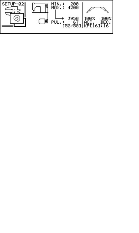
 ROTATION (SPEED, ACCELERATION)
Speed:
Through the 
 buttons move to “MIN.:”; this symbol shows the minimum speed of the sewing machine. Through the
  and
and  buttons it is possible to define the required value (usually 200 rpm).
COMELZ |
ARGO 42/A |
12 |
|
|
|
Through the 
 buttons move to “MAX.:”; through the
  and
and  buttons it is possible to define the value that limits the top speed of the sewing machine. The speed reached by the motor when the machine is turning at top speed is displayed on the lower line (this is only a reference value and it can not be changed).
Pulley:
The correct choice of the pulley is very important to obtain the best performances from the motor. With the cursor on the
“PUL.:” position, enter the diameter of the pulley fitted to the motor (this value is stamped on the pulley).
If the pulley was correctly chosen, the top speed of the machine is reached when the motor runs at 4500 rpm. If the motor runs much faster (6000 rpm) or much slower (less than 3000 rpm) it is advisable to replace the pulley following the suggestion in brackets. After replacing the pulley it is necessary to set again the “zero reference position”.
Acceleration:
While accelerating and decelerating, the motor can deliver its full power or a lower power (to comply with the requirements of the
machine). Move to the “ACC.:” and “DEC.:” symbols and, through the  and
and  buttons, define the value that will represent the percentage of power utilization (the first value for acceleration, the second one for deceleration). For the deceleration value it is possible to set a value greater than 100% (between 100% and 150%). Caution! Use values of DEC greater than 100% only if an extremely high deceleration is needed (in fact the machine may stop so quickly that the needle can bounce back, and the stitch counter may result inaccurate).
Quietness and accuracy when stopping:
In case of real need, it is possible to increase the quietness when stopping by reducing the accuracy (KP<16). Values bigger than 16 are not suggested since the stopping accuracy has already reached its best.
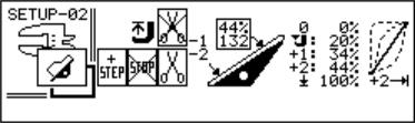
 TREADLE
When the treadle is released it is in the 0 position.
Heel to move to -1 and -2 positions. Position -1 is related to the presser foot lifting function (light heeling position). Position -2 is usually related to the thread trimming function (full heeling position).
The icons on the left will allow to:
−Activate the thread trimmer at -1 position or -2 position. Caution! Activate the thread trimmer at -1 position only if necessary; in fact it will not possible anymore to rise the presser foot in the middle of the seam.
−Activate an emergency stop at -2 position. By activating this feature it is possible to stop the rotation of motor when it is running in automatic or semi-automatic mode. Caution! Use this feature only if necessary; in fact accidental movement of the pedal to -2 position will interrupt the Sewing Program and the active stitch counter.
−Move to the next Step of the Sewing Program by moving the pedal at -2 position. Caution! Use this feature only if necessary; in fact accidental movement of the pedal to -2 position will cause an undesired
change of the Step of the Program.
Moving the treadle from 0 to +1 does not operate the motor. If the presser foot is up, it moves down when the value assigned to  is reached.
The motor runs at its minimum speed when the +1 position is reached and maintains this speed till the +2 position is reached. Positions  , +1 and +2 can be modified (standard values are shown in the picture above). These values represent the percentage of the treadle movement between 0 and
  .
.
Between +2 and  , the speed increases until it reaches its maximum. This variation occurs with the progression indicated in the treadle response curve. Besides the standard progression, it is possible to select instantaneous response (suitable for some serial operations), fast response (for over-lock machines or some chain-stitch machines), slow response (for improved control at low
speeds). Through the  and
and  buttons it is possible to select the required treadle response mode. The box above the pedal drawing contains two values:
The value on the top indicates the pedal position. That value is -2 when the pedal is at -2 position; it is -1 when the pedal is at -1 position; it is -9% to 99% when the pedal is from release position to all the way down position. When the pedal is released that
COMELZ |
ARGO 42/A |
13 |
|
|
|
value should be 0%. If not, it is possible to perform little adjustments to the tuning of the pedal by moving the cursor on this
percentage register and pressing the button twice. Major adjustments to the tuning of the pedal must be done using the two potentiometers installed on the pedal electronic board KK81.
The value on the bottom indicates the pedal position. That value should be below 30 when the pedal is all the way back, it should be about 108 (between 100 and 115) when the pedal is at rest position; it should be 255 when the pedal all the way down.
COVER PAGES
Cover Pages are pages displayed at motor on. They are linked to a Sewing Program and allow the operator to perform (in a simple way) changes only to those parameters that need to be adjusted.
Move the cursor on the “Cover Page” icon on page Setup -03 and use the 
 buttons to select the type of Cover Page desired. Choose among the above shown icons, which represent respectively:
−No Cover Pages active
−Standard Cover Page
−Band Cover Page (for automatic waist-band machines. See separate manual “Waist-band”)
−Back-Latch Cover Page (for over-lock machines with automatic back-latch device. See separate manual “Back-Latch”)
Standard Cover Page Setup: select the “Cover Page” icon and then recall the underlying page through the  button.
In this page it is possible to decide how many parameters the operator will be allowed to control (from 1 to 8). Move the cursor to each parameter and activate it with  or deactivate it with
  . After a parameter is active, it is possible to assign to it a 12 letter name (by moving the cursor on each character on the right of the parameter and then selecting the desired character with the
 buttons).
The “DEVICES” icon allows you to decide if in the cover page you want to display also the machine speed and the icons for needle position (up-down), presser foot (up-down) and trimmer (yes, no). Move the cursor to “DEVICES” and press  to display
the icons or  to hide them.
The “COVER N:” icon allows you to decide the maximum number of Cover Pages the operator can access. The default number is 100 but it can be reduced even to 1 to avoid the operator to change Cover Page and move to a Cover Page that executes the wrong Sewing Program.
Once the Cover Page is set-up see paragraph “USE OF STANDARD COVER PAGES” page 37 to learn how link a Cover Page to a Sewing Program and how to link a Cover Page parameter to a Sewing Program parameter.
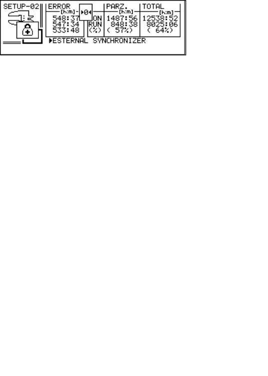
 MOTOR DIAGNOSIS
Motor Timers: The column on the right shows respectively: the total time the motor has been turned on (in hours and minutes) since it left the factory; the total time the motor has been running (in hours and minutes) since it left the factory; percentage of the running time versus motor-on time. The column in the middle shows respectively: the total time the motor has been turned on (in hours and minutes) since the last timer reset; the total time the motor has been running (in hours and minutes) since the last timer reset; percentage of the running time versus motor-on time.
Malfunctions: The column on the left in this page shows all the problems that caused the motor to stop running. They are listed in descending order by the time when the problem occurred (these times refer to the partial timer). See paragraph MAINTENANCE page 39. It is possible to reset the partial timers and the list of problems by moving the cursor on the “0” icon and by pressing the
 button.

COMELZ |
ARGO 42/A |
14 |
|
|
|
Running the machine without synchronizer: it is possible to run the machine without synchronizer. Move the cursor to
EXTERNAL SYNCHRONIZER and press the  button (then press the button to confirm). From now on the machine will not need anymore an external synchronizer to run, but it will use the motor internal encoder (that has a resolution of 1024 pulses/revolution). The stitch counting and speed control will remain valid and the transmission ratio will be 1:1. That means the number of stitches is the number of motor revolutions and the speed is the motor speed. If pulley and hand-wheel are the same size, everything will work fine except for the stopping positions; in fact the motor will not detect every little belt slipping and, as time goes by, the stopping positions will not be anymore accurate. Basically this feature is good to test run a motor (or machine) without the need to install a synchronizer; to run machines where stopping positions are not important; to run machines installed with ratio 1:1 and equipped with timing belt and pulleys (of course the speed of the machine must not exceed 6000RPM).

 PROTECTED ACCESS SETUP
Move the cursor on the “Code Setup” icon on page Setup -03 and press the  button to disable codes. When the codes are disabled it is possible to move from the Program area to the Set-up area, to write into the KK195 and to modify Sewing Programs without the need of entering any code.
Move the cursor on the “Code Setup” icon on page Setup -03 and press the  enable codes. When the codes are enabled it is required to enter the correct code to perform certain operations. There are two different codes (PRG code to protect the Sewing Programs and STP code to protect the machine Set-up); the default value for both codes is 000. For more protection it is possible to change the codes from 000 to one of the more than 50000 different possible codes. In order to do that, move the cursor on the
“Code Setup” icon on page Setup -03, press the  button and set the STP code or the PRG code or both codes to the desired value.
SETUP -03 / machine devices
This page shows all devices that can equip the sewing machine selected on page Setup -01. Parameters must be defined for each device actually available on the machine. Each device not available on the machine must be canceled (the cancellation is
necessary to prevent slowing down during operations). Select the device to be canceled and press the  button to deactivate it (a cross will appear on the icon).
To program available devices, select each one through the 

 buttons, press the
  button to activate it and then recall
the underlying page through the  button; define then the specific values as explained below. Press the same
  button to return to the main page. For the photocell and for the safety switch it is sufficient to select the required type by moving through the
options by means of the  button.
 THREAD TRIMMER
Select the “thread trimmer” icon on page Setup -03 and press the  button to access the parameters to be defined.
Many different types of thread trimmer are commonly used. For this reason two different pages have been defined, each one automatically displayed according to the type of machine selected on page Setup -01.
In case a lock-stitch machine (i.e. with thread trimmer triggered while the machine is rotating) was previously selected, the following page will be displayed:
COMELZ |
ARGO 42/A |
15 |
|
|
|
Defining parameters consists in setting the trimmer engagement phase, the trimmer disengagement phase and the trimming speed. To set the engagement position (or the disengagement position) move the needle to the desired position and confirm the
assigned value through the  button. Then the value can be modified through the
  and
and  buttons. Normally the engagement
position is the first stopping position (needle down); it is possible to set the engagement position value to “I” (press the  button until “I” will appear) in order to have the engagement position always in first stopping position.
For those machines with vertical axis rotary hook, it is necessary to stop the machine in engagement position for a certain time. Set
this delay in the second engagement option ( ).
).
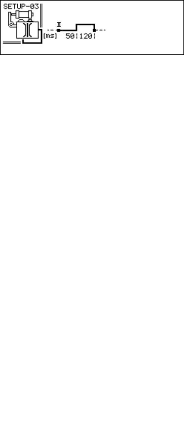
In case a chain-stitch machine (i.e. equipped with trimmer firing after machine is stopped with needle up) was previously selected, the following page will be displayed:
Defining parameters consists in setting the pause after stopping in the second position and before activating the trimmer and the trimmer duration signal.
Some machines are fitted with a second thread trimmer (upper), also independent; in this case the second thread trimmer must be
activated by moving on the upper trimmer icon and by pressing the  button; then its parameters have to be programmed in the same way as the first trimmer.
The “slow start” is defined by a number of stitches and a speed. When the number of stitches is different than ---, it is possible to activate the slow start within each single Sewing Program, by selecting the icon that indicates “thread trimmer followed by slow start”.
On those machines where the return of the thread trimmer is con trolled by a safety switch, it is necessary to activate the Safety Switch device as shown further on.
 TENSION RELEASE
Select the “tension release” icon on page Setup -03 and press the  button to access the parameters to be defined.
In case a lock-stitch machine was previously selected, the following page will be displayed:
Defining parameters consists in setting the signal start position and its duration after stopping.
In case a chain-stitch machine was previously selected, the following page will be displayed:
Defining parameters consists in setting the pause before activating the tension release after stopping in second position and the duration of the signal.
COMELZ |
ARGO 42/A |
16 |
|
|
|
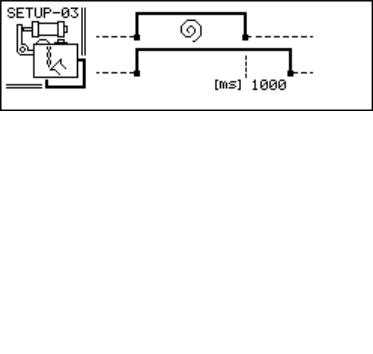
 THREAD WIPER
Select the “thread wiper” icon on page Setup -03 and press the |
button to access the parameters to be defined. |
Defining parameters consists in setting the pause before activating the wiper after stopping in second position, the duration of the signal, the pause before the presser foot rises (to allow the wiper to move back to home position). With an air blow thread wiper, the presser foot can rise as soon as the second position is reached. This operational mode is obtained by setting to “0” the pause before raising the presser foot.
 PRESSER FOOT LIFTER
Select the “presser foot lifter” icon on page Setup -03 and press the |
button to access the parameters to be defined. |
The presser foot is operated by a solenoid or by an air cylinder driven by a solenoid valve.
Defining parameters consists in setting the duration of the pickup signal (duration of 30V signal to rise the foot), the holding voltage (voltage high enough to hold up the foot and low enough not to burn the solenoid after long time), the duration of the holding voltage and at last the delay before starting the rotation (to allow the foot to be completely down before start running). The duration of the holding voltage can be indefinitely extended by entering the “ ” value. The holding duration and the holding voltage must be accurately defined for those presser foot lifters operated by an electric solenoid, to avoid over-heating (or, contrariwise, too low holding force).
For pneumatic presser foot lifters (operated by a solenoid valve) the holding voltage must be kept equal to the rated voltage of the solenoid valve.
For both types of presser foot lifter it is advised to delay the start of the machine to allow the presser foot to go down.
With the top right icon it is possible to select if, while sewing, the presser foot must lift as soon as the rotation stops or if it must
remain low (use the 
 buttons).
With the lower icon it is possible to select if the presser foot must remain low after operating the thread trimmer or if it must automatically rise (use the 
 buttons). This will also be the position of the presser foot when the machine is turned on.
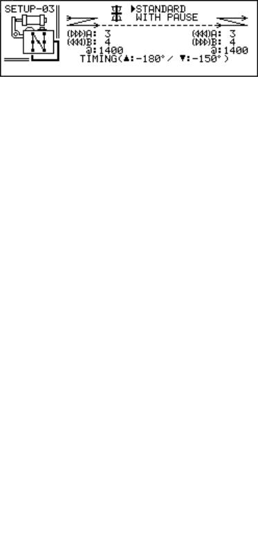
 BACK-TACK
Select the “back-tack” icon on page Setup -03 and press the |
button to access the parameters to be defined. |
The back-tack is obtained through the feed reversal, actuated by an electric or pneumatic device.
Defining parameters consists in defining two types of back-tack to be freely used within Sewing Programs.
The standard back-tack (fast back-tack) is defined by: number of stitches forward, number of stitches backward, back-tack speed and timing of the reversal point (it is necessary to define a correct advance depending upon the response time of the reversal mechanism and upon the back-tack speed).
COMELZ |
ARGO 42/A |
17 |
|
|
|
The back-tack with pauses (accurate back-tack, i.e. when the needle enters in the same holes made while sewing forward) is defined by: number of stitches forward, number of stitches backward, speed and stand-by pause for feed reversal.
For needle feed machines, the top right icon selects a specific operation mode. With these machines, it is necessary that the feed reversal is activated while the needle is outside the needle plate, therefore, also after a pause (back-tack with pauses), the reversal will occur only after restarting in the previous direction, according to the phase set for the standard back-tack.
Afterwards, during utilization, by using the MT800 console to write Sewing Programs it will be possible to select whether to sew a back-tack: standard or with pauses, at the beginning or at the end, simple or double.
Also with the MT600 console it is possible to make the same choices, with the exception of the choice between a standard backtack and one with pauses (this must be done while defining the configuration).
 NEEDLE COOLING
The needle cooling is a running signal. Select the “needle cooling” icon on page Setup -03 and press the  button to access the parameters to be defined.
Defining parameters consists in defining the delay before stopping the air blow after stopping the rotation and the minimum speed at which the machine must run in order to activate the needle cooling. If the minimum speed is set to 0 the needle cooling signal is active whenever the machine is running.
 CHAIN SUCTION (VENTURI)
(Only for over-lock machines). The chain suction is a running signal. Select the “chain suction” icon on page Setup -03 and press the  button to access the parameters to be defined.
Defining parameters consists in defining the delay before interrupting the suction after stopping the rotation.

 PHOTOCELL
Select the “photocell” icon on page Setup -03 and use the 
 buttons to select the photocell fitted to the machine. Choose among the above shown icons, that represent respectively:
•photocell with 0 V output signal when uncovered (and +5 V output signal when covered). This is the standard Comelz photocell.
•photocell with +5 V output signal when uncovered (and 0 V output signal when covered).
See USE OF THE PHOTOCELL page 31.

 SAFETY SWITCH
This functionality is generally used to check the thread trimmer return on some chain-stitch machines (but it can be used as an
emergency stop input). Select the “safety switch” icon on page Setup -03 and use the 
 buttons to select the operating mode (normally closed or normally open). The rotation of the machine is allowed only when the safety switch status agrees. In case this functionality is activated on machines that do not have it, the machine would then be waiting for a signal that could never come and therefore it could not be operated.
The device connected to this input must be a micro-switch (two wires) or a NPN type device.
Loading...