

Tri Tool 620SB User Manual
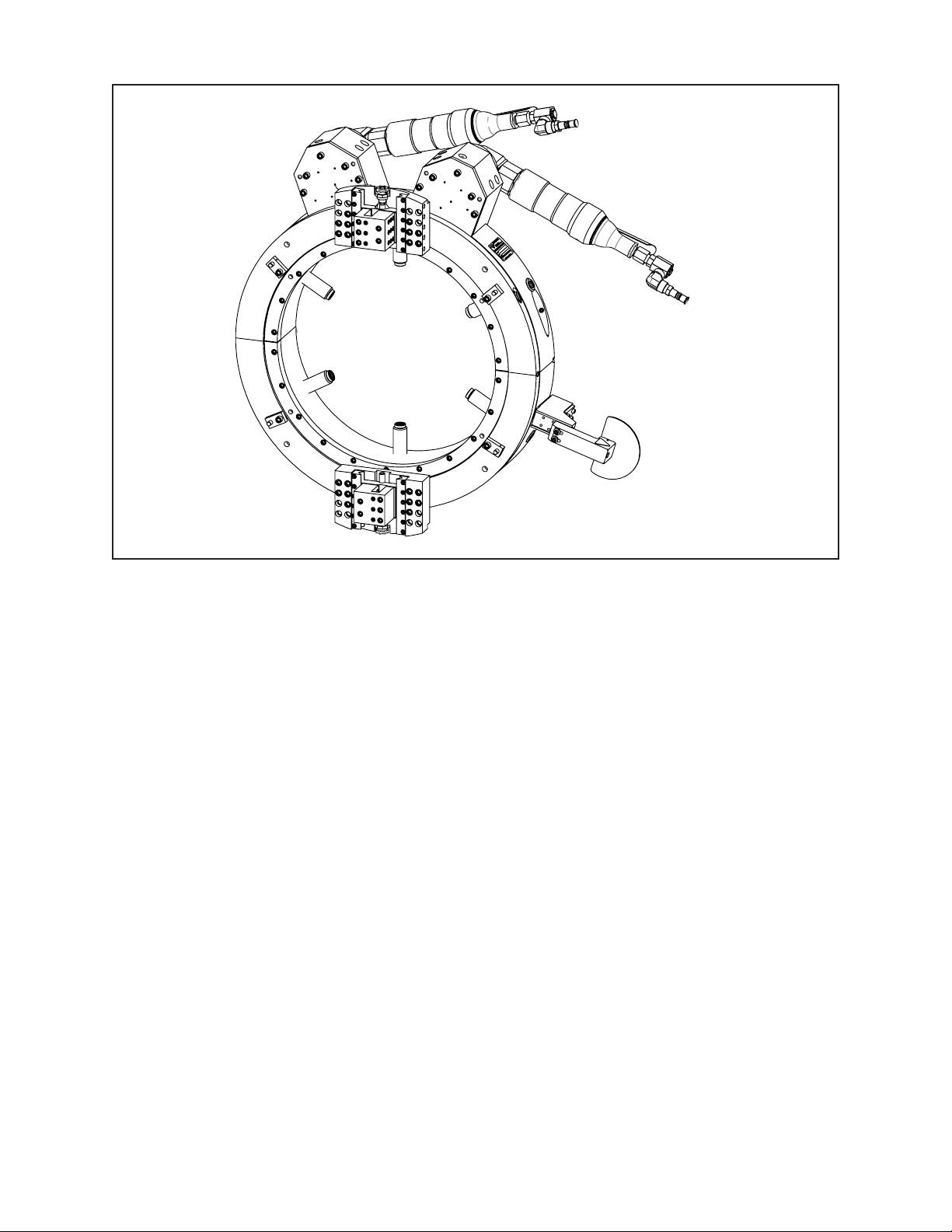
TABLE OF CONTENTS
CUSTOMER MESSAGE Inside Front Cover
SAFETY PRECAUTIONS 3
92-0220 Rev. 131230
Model 620SB Low Prole Clamshell, Air
GENERAL DESCRIPTION 6
SPECIFICATIONS 7
MAINTENANCE 9
OPERATION 18
CUTTING SPEEDS 31
TOOL BITS 32
CLAMPING PAD SETS 40
TROUBLE SHOOTING 41
ACCESSORIES 44
ILLUSTRATED PARTS BREAKDOWN 45
TOOL BIT RESHARPENING POLICY Inside Back Cover
WARRANTY INFORMATION Inside Back Cover

Copyright 2013
Proprietary property of TRI TOOL Inc.
No reproduction, use, or duplication of the information
shown hereon is permitted without the express written
consent of TRI TOOL Inc.

SAFETY PRECAUTIONS
IN GENERAL
When using rotating head cutting equipment, basic safety precautions should always
be followed to reduce the risk of personal injury.
Operate this tool only in accordance with specic operating instructions.
Do not override the deadman switch on the power unit. Locking down,
WARNING:
DRESS CONSIDERATIONS
obstructing, or in any way defeating the deadman switch on the power drive
unit may result in serious injury.
Model 620SB Low Prole Clamshell, Air
Use standard safety equipment. Hard hats, safety shoes, safety harnesses,
protective clothes, and other safety devices should always be used when
appropriate.
Use safety glasses. Do not operate cutting tools without eye protection.
Dress properly. Do not wear loose clothing or jewelry. They can be caught in
rotating and moving parts. Avoid slippery oors or wear nonskid footwear. If you
have long hair, wear protective hair covering to contain it.
WORK AREA
Keep the work area clean.
Keep the area well lit. Keep electrical cords, cables, rags, rigging straps, and etc.
clear of rotating equipment. Do not use power-cutting tools in the presence of
ammable liquids and gasses.
Keep visitors away. Do not let visitors or untrained personnel at or near operating
tools. Enforce eye protection requirements for all observers.
Do not over reach. Keep proper footing at all times.
Stay alert. Watch what you are doing. Use common sense. Do not operate tools
when you are tired.
92-0220 : Rev. 131230
3

TRI TOOL INC.
TOOL CARE
Maintain tools with care. Keep tools in good operating condition. Sharp tool bits
perform better and safer than dull tool bits. Well maintained tools function properly
when needed.
Check for damaged parts. If a tool has malfunctioned, been dropped or hit, it
must be checked for damage. Run no-load tests and feed function checks. Do a
complete visual inspection.
Electric motors. Use only with proper AC voltage power sources and observe all
normal electric shock hazard procedures.
Do not abuse power and control cords. Pulling or running over cords and cables can
result in electrical shock hazards and malfunctions. Keep control and power cords
out of all cutting uids and water.
Hydraulic drives. Observe proper procedures for electrically driven power sources.
Avoid damage to hydraulic lines. Keep quick-disconnects clean. Grit contamination
causes malfunctions.
Air tools. Check the exhaust mufer. Broken or damaged mufers can restrict
air ow or cause excessive noise. Use air motors only with a ltered, lubricated
and regulated air supply. Dirty air, low-pressure air or over pressure air will cause
malfunctions, including delayed starting.
AREA EQUIPMENT
Secure work. Whenever possible use clamps, vises, chains and straps to secure
pipe.
Make sure the tool is secured; it is safer to have both hands free to operate the tool.
TOOL USE
Use the right tool and tool bit for the job. Do not use a tool, which is incorrect for the
job you are doing.
Keep the tool bits fully engaged in the tool bit holders. Loose bits are a safety
hazard.
4
92-0220 : Rev. 131230

Model 620SB Low Prole Clamshell, Air
Disconnect power supply during setup and maintenance. Use all ‘Stop’ or Shut off’
features available when changing or adjusting tool bits, maintaining the tool, or when
the tool is not in use.
Remove adjusting keys and wrenches before applying power to the equipment.
Develop a habit of checking the tool before turning it on to make sure that all keys
and wrenches have been removed.
Do not force tools. Tools and tool bits function better and safer when used at the
feed and speed rate for which they were designed.
Do not reach into rotating equipment. Do not reach into the rotating head stock to
clear chips, to make adjustments, or to check surface nish. A machine designed to
cut steel will not stop for a hand or an arm.
Handle chips with care. Chips have very sharp edges and are hot. Do not try to pull
chips apart with your hands; they are very tough.
Avoid unintentional starts. Do not carry or handle tools with your hand on the
operating switches or levers. Do not lay the tool down in a manner that will start the
drive. Do not allow the tool to ip around or move when adjusting or changing tool
bits.
Store idle tools properly. Disconnect tools from the power source and store in a safe
place. Remove tool bits for safe handling of the tool.
92-0220 : Rev. 131230
5

TRI TOOL INC.
GENERAL DESCRIPTION
The Model 620SB Low-Prole Clamshell (P/N 01-1146) is a split-frame pipe lathe
designed for severing and beveling in-line pipe with a minimum range of 16” through
20” pipe with minimal radial and axial clearance.
Using standard Tool Blocks the Model 620SB may be congured to perform the
following operations:
Sever in-line pipe.
Sever and bevel in-line pipe.
Sever and double bevel in-line pipe.
DESIGN AND OPERATING FEATURES
The easily adjustable precision bearing surfaces pre-load and stabilize the rotating
head to provide long life, low maintenance, stability, and precision.
The Clamshell splits into two halves for mounting on closed loop systems.
All parts are secured to the two halves, thus avoiding the loss of parts and at the
same time providing maximum ease of handling.
The Clamshell is equipped with Adjustable Clamping Pads and Jackscrews for
out-of-round pipe conditions.
Dual Tool Blocks with Auto-feed Sprockets and Adjustable Slides provide maximum
maintainability, life, and operator safety, with a minimum of operator training.
The Auto-feed Sprockets provide .004” (.10 mm) of radial feed per revolution of the
Headstock for a controlled depth of cut.
The drive gears and bearing surfaces are covered for operator safety and are sealed
to provide protection from dust and chips.
The operator’s controls are located away from the rotating Headstock for the
operator’s safety.
A modular design concept provides quick, easy maintenance and maximum
versatility in the drive and tooling options.
Two detachable right angle Air Motors provide maximum handling ease and low
axial clearance.
6
92-0220 : Rev. 131230
Model 620SB Low Prole Clamshell, Air
123.4
SPECIFICATIONS
Model 620SB with the standard Air Motors.
Weight: 377 lbs. (171 kg) without the Air Motors attached.
Power Requirements: 150 cfm at 90 psi with the standard Air Motor.
(71 L/s at 6.3 kg/cm2)
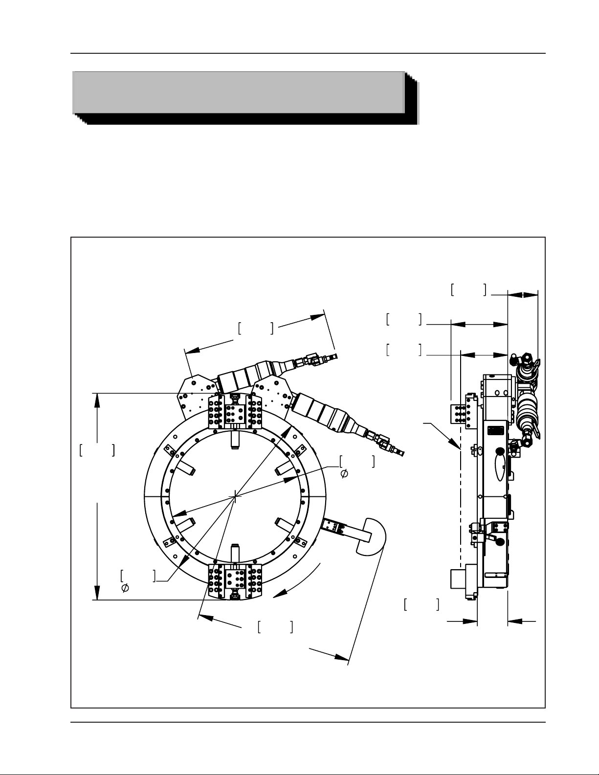
Envelope, Model 620SB, Air, Clamshell
4.86
844.6
33.25
MAX
PARTS
741.7
29.20
591.4
23.28
640.6
25.22
MAX HEIGHT
ROTATION
538.5
21.20
231.9
9.13
192.5
7.58
NOMINAL
SEVER
LINE
124.5
4.90
BASIC
MACHINE
92-0220 : Rev. 131230
7

TRI TOOL INC.
Cutting Capacities* on 12" through 20" Pipe
Note: Capacity may exceed the maximum wall thickness for small pipe sizes
Severing with standard procedures 2.50" (63.5 mm) wall
Severing and single beveling 1.25" (31.8 mm) wall
Severing and double beveling 1.25" (31.8 mm) wall
Severing and beveling with special procedures 2.00" (50.8 mm) wall
Clearances
Rotating parts diameter 33.25" (844.6 mm)
Main Frame diameter 29.20" (741.7 mm)
Axial clearance required relative to center-line of the cut:
Mounting side 7.58" (192.5 mm)
Side opposite of the frame 1.56" (39.6 mm)
Radial Clearance Over the Pipe or Tube
Pipe Size True Diameter Clearance Tool Blocks
20" 20.00" 508 mm 6.63" 168.4 mm
18" 18.00" 457 mm 6.63" 168.4 mm
16" 16.00" 406 mm 6.63" 168.4 mm
8
92-0220 : Rev. 131230
Model 620SB Low Prole Clamshell, Air
MAINTENANCE
All components should be cleaned and coated with a light lm of oil prior to use. Use
a clean, non-detergent oil, preferable SAE 10 (90 SSU or lighter).
Air supply for the Model 620SB Clamshell with dual Air Motors requires an adequate
lter/regulator/lubricator (FRL) to be used.
The Motor warranty is void if damage occurs from contaminated air or lack of
NOTE:
lubrication.
Clean Up
If the Clamshell is operated in such a manner that the Tool Blocks collect debris
while cutting, the Tool Blocks and the Feed Screws should be cleaned after each
cutting operation.
RECOMMENDED MAINTENANCE SCHEDULE
Daily maintenance when the unit is in operation:
Wipe the unit down and spray with rust preventative under severe humidity
conditions.
Visually inspect for loose screws, missing screws, damage, etc.
After every 20 hours of actual operation:
Check adjustment of the Main Bearing pre-load.
Lubricate the male and female Tool Block Slides and the Feed Screw. Refer
to Tool Block Maintenance located later in this section.
92-0220 : Rev. 131230
9

TRI TOOL INC.
After every 40 hours of actual operation:
Thoroughly clean and lubricate Main Gear, Drive Gear, male and female Tool
Slides, Feed Screws, and Tripper Block Assy.
Non-scheduled maintenance:
Readjust the Main Bearing pre-load if the Clamshell generates excessive
heat or if the Main Bearing becomes loose. Refer to Adjustment of the Main
Bearing pre-load.
Thoroughly clean and check the Tool Blocks in the event of feed problems.
STORAGE
If the Clamshell is to be stored or if it will remain out of service for a signicant
period of time (30 days or more), it should be thoroughly cleaned lubricated and
sprayed with a rust preventative prior to storage.
Remove the airline Quick Disconnect and spray it with a lightweight oil.
Squirt oil into the male Quick Disconnect.
Reconnect the airline and turn on the Air Motor for 1 or 2 seconds to disperse oil
throughout the vanes and rotor.
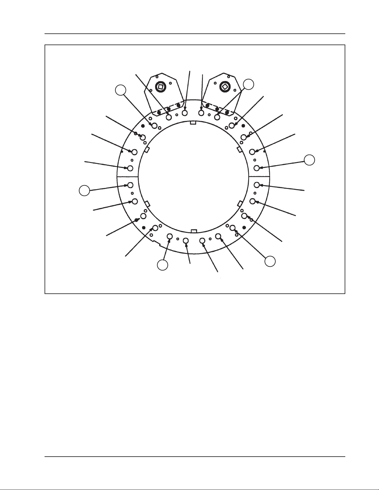
ADJUSTMENT OF THE MAIN BEARING PRE-LOAD
Loosen all Bearing Adjustment Lock Screws about 1/2 turn (1 through 24).
Turn in Bearing Adjustment Screws (1, 5, 9, 13, 17, and 21) so that they are
snugged tightly.
This insures that the Bearings are fully pushed forward. Refer to the Bearing
Adjustment Screw locations.
Lightly turn in the remaining Bearing Adjustment Screws in the order shown until all
of the Bearings make contact with the Headstock.
Relax Bearing Adjustment Screws (1, 5, 9, 13, 17, and 21) and resnug them so that
all of the Bearing Adjustment Screws are evenly loaded against the Bearings.
Connect the air supply and apply power to the Clamshell so that it is running at full
speed.
10
92-0220 : Rev. 131230
Model 620SB Low Prole Clamshell, Air
Bearing Adjustment Screw Locations
20
19
18
24
23
1
21
22
2
3
4
5
6
7
17
16
15
14
13
12
11
10
9
8
Adjust the Bearing Adjustment Screws (1 through 24) so that the Clamshell rotation
slows slightly.
Listen for a change in the sound of the Air Motors.
Adjust the Bearing Adjustment Screws in small increments so that the Bearings are
loaded evenly.
All of the Bearing Adjustment Screws should be snugged to ensure that the
Bearings are uniformly loaded.
The safe torque range on the Bearing Adjustment Screws is 1 to 3 in-lbs.
(.1 to .3 N-m).
Over-tightening the Bearing Adjustment Screws will result in accelerated bearing
wear and lower available power.
92-0220 : Rev. 131230
11
TRI TOOL INC.
Lock the Bearing pre-load by tightening the Bearing Adjustment Lock Screws.
(1 through 24).
The safe torque should be 8 to 10 ft-lbs. (11 to 14 N-m).
Too much torque may crack the Bearing while too little torque may allow the
WARNING:
Bearing pre-load to relax.
INSPECTION OF THE MAIN GEAR
If the Headstock does not run smoothly, even after adjustment, inspect the Main
Gear to ensure that no chips, dirt or dust has damaged the gear.
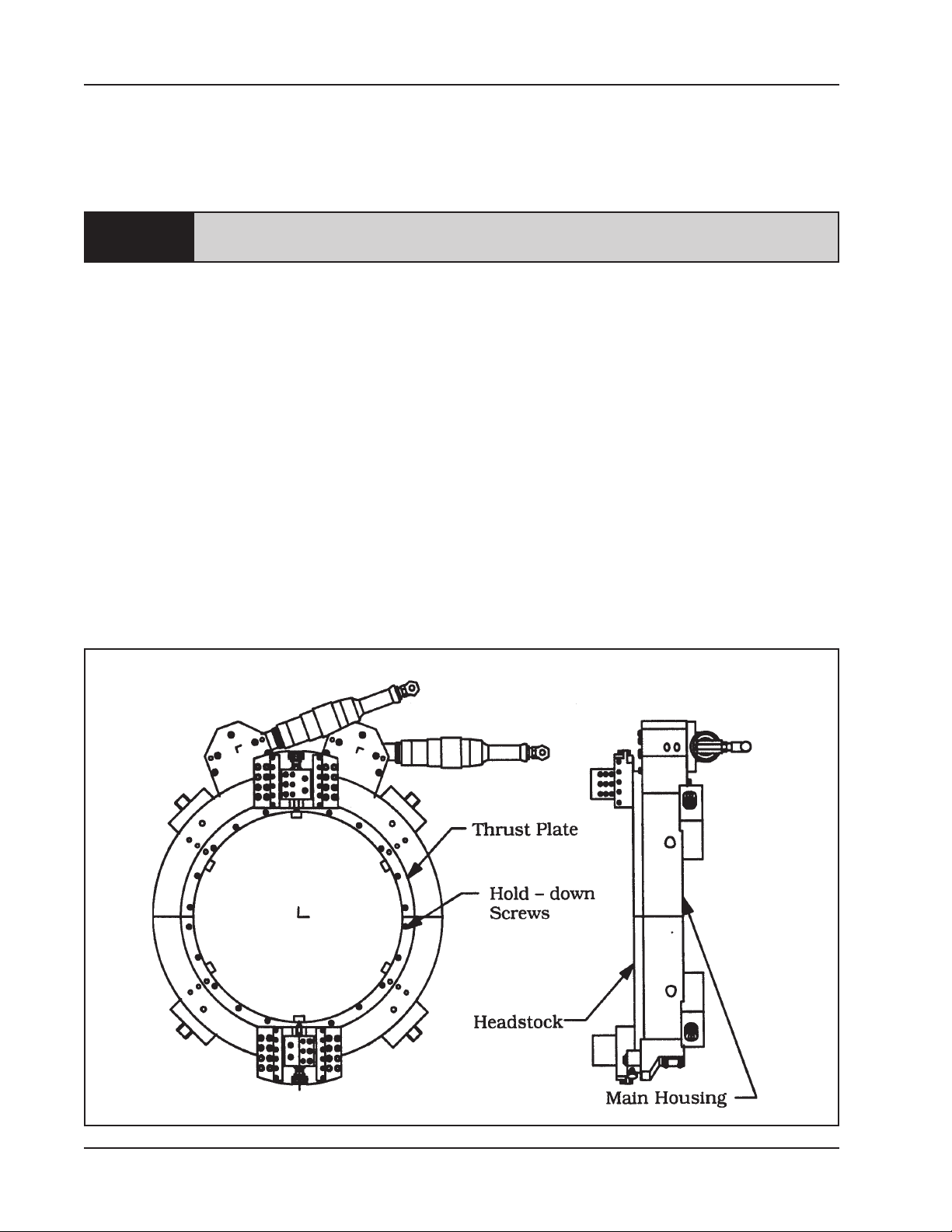
Remove both of the front Thrust Plates by removing the twenty-two (22) Hold Down
Screws.
Lift the Headstock from the Housing. Refer to the 'Clamshell Nomenclature'.
The Main Gear and the Main Bearing may now be inspected.
Check the Bearing, Housing, and the race on the Gear.
All surfaces should be smooth, without scratches, and they should feature even
wear patterns over the entire surface.
Clamshell Nomenclature
12
92-0220 : Rev. 131230
Model 620SB Low Prole Clamshell, Air
Check the Housing cavity for chips, dirt and/or corrosion.
To reassemble, wipe clean all of the Bearing surfaces and clean the Housing cavity.
Regrease the Gear using a lubricant approved by TRI TOOL Inc. Refer to the
Lubricant Recommendations located later in this section.
Place the Headstock carefully back into the Housing.
Bolt the Front Thrust Plates back into place.
If the bearing pre-load was properly adjusted before being disassembled, then it will
still be adjusted when reassembled.
DRIVE GEAR AND MAIN GEAR LUBRICATION
Remove the Drive Housing.
Inspect both Drive and Main Gears for chips or burrs and clean as required.
Coat the teeth of the Drive Gear and the Main Gear with a grease which is approved
by TRI TOOL. Refer to the 'Tripper Block Assy. Lubrication and Tripper Shaft
adjustment' located later in this section.
TOOL BLOCK MAINTENANCE
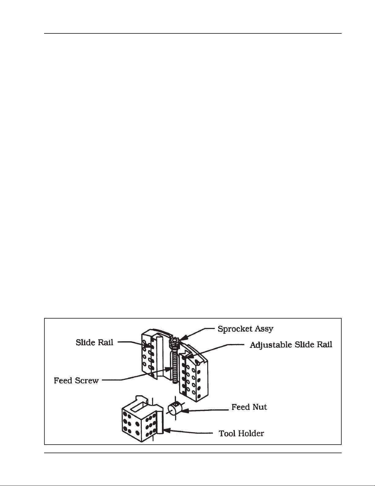
Clean the Slide Rails, the Feed Nut, the Sprocket Assy. and the Feed Screw.
Inspect these parts for damage and replace as required.
Lubricate and reassemble the Tool Block. Refer to the 'Tool Block Assembly'.
Tool Block Assembly
92-0220 : Rev. 131230
13
TRI TOOL INC.
Use lubricant on the Feed Screw sparingly or wipe to a lm condition.
NOTE:
Excess lubricant will collect grit and/or chips and tend to cause thread jamming
and/or damage.
Adjust the Adjustable Slide Rail to provide a rm, but not excessive rotational
pressure on the Sprocket.
The Slide Rails must be over-tightened to squeeze the oil into a thin lm against the
male and female surfaces of the Slide Rails.
Reset for proper operation.
If the Mounting Bracket has been overstressed, the Slide Rails may appear to
NOTE:
loosen when mounted if they were adjusted off of the Clamshell.
Adjustment when mounted provides the most satisfactory results.
TOOL HOLDER ADJUSTMENT
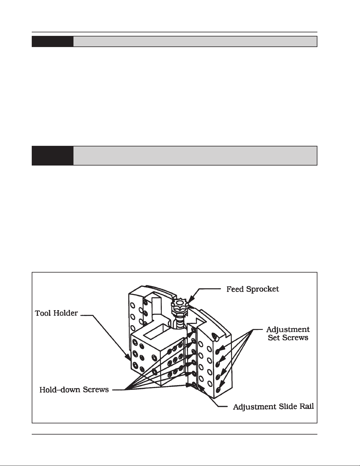
Loosen the Hold-down Screws on the Adjustable Slide Rail.
Run the Tool Holder to the most outward position.
Using the Adjustment Set Screws, apply a light force to the side of the Adjustable
Slide Rail so that it is in positive contact with the Tool Holder.
Tool Holder Adjustment
14
92-0220 : Rev. 131230

Model 620SB Low Prole Clamshell, Air
Adjust only those screws, which bear directly in line with the Tool Holder.
Tighten the Hold down Screws to about 12 to 24 in-lbs. (1.4 to 2.7 N-m). (Finger tight
using a hex key)
Using the Spanner Wrench, run the Tool Holder to the inward most position.
Note any changes in the feed pressure.
Adjust the remaining Adjustment Set Screws so that the Tool Holder has a smooth,
even feel.
Run the Tool Holder the full length of the Slide Rail.
Tightly lock the Adjustable Slide Rail in place with the Hold-down Screws and fully
snug the Adjustment Set Screws.
Check that the Tool Holder runs smoothly and evenly for the full length of travel.
Readjust as necessary.
The Tool Holder should move snugly.
In general, when the Slide Rail is set correctly, the Feed Sprocket cannot be turned
by hand but may be turned easily with the Spanner Wrench.
The torque on the Spanner Wrench should be about 2 to 5 ft-lbs. (2.7 to 6.8 N-m).
AIR MOTOR LUBRICATION
No direct maintenance is normally required on the Air Motors.
However, the air supply must ow through a lter/regulator/lubricator (FRL) unit or
separate units before arriving at the motor.
The FRL unit must be maintained as required (frequency dependent on the basic air
supply) to keep the water trap drained, lter cleaned and the lubrication oil reservoir
lled so that a drop of oil every 2 to 5 seconds is owing.
If the Clamshell is to be left idle for 24 hours or more after being run on ‘wet’ air, it
is advisable to squirt oil directly into the motor inlet and run the motor for 2 to 3
seconds. This will prevent rusting and ‘freezing’ of the rotor vanes.
92-0220 : Rev. 131230
15
TRI TOOL INC.
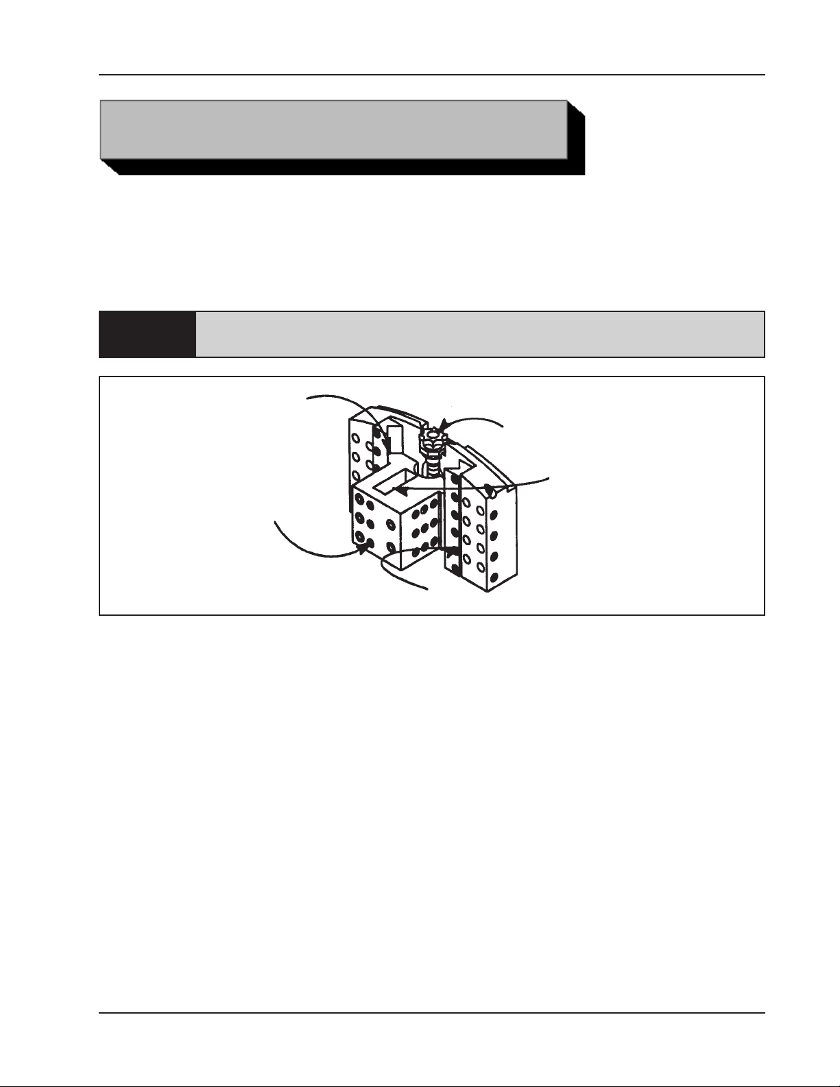
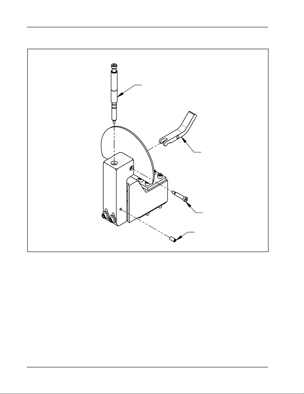
BALL PLUNGER
TRIPPER BLOCK ASSY LUBRICATION AND TRIPPER SHAFT ADJUSTMENT
Tripper Shaft Installation
TRIPPER SHAFT
ASSEMBLY
TRIPPER
LEVER
SHOULDER
BOLT
SET SCREW
Back off the Ball Plunger Set Screw until it disengages from the Tripper Shaft
Assembly.
Remove the Shoulder Bolt, and then remove the Tripper Lever.
Remove the Tripper Shaft Assembly from the block, and then degrease and clean all
parts.
Apply fresh lubrication to the Tripper Shaft Assembly and to the Shoulder Bolt.
Reassemble in reverse order.
16
92-0220 : Rev. 131230

Model 620SB Low Prole Clamshell, Air
LUBRICANT RECOMMENDATIONS
The Drive Gears require a high string lubrication grease such as “Chevron Utility
Grease, light, high string for gears” (P/N 68-0020).
The Slide Rails and Tool Blocks require a light oil such as SAE 10 light machine oil.
The Feed Screw for the Tool Block and the Tripper Block Assy require a SAE 10
light machine oil for normal conditions and under dusty conditions a silicone,
graphite or molybdenum disulde ‘dry’ lubricant.
A light lm of all-purpose grease may be used, but it must be checked for grit
NOTE:
contamination frequently.
The Air Motor requires a Class 2 lubricant, viscosity of 100 to 200 SSU at 100OF
(38OC) minimum aniline point of 200OF (93OC).
Tri Tool Inc.– Air Tool Lubricant (P/N 68-0022)
AMOCO – American Industrial Oil No. 32
Atlantic Richeld – Duro Oil S-150
Chevron – A.W. Machine Oil 32
Exxon – Nuto H32
Shell – Tellus Oil 32
The bearings in the Air Motor are sealed and do not require any lubrication.
92-0220 : Rev. 131230
17
TRI TOOL INC.
OPERATION
Read the operation instructions carefully before attempting to operate the Model
620SB Low Prole Clamshell.
Congure the Clamshell for the specic task required.
Mount the Tool Blocks and Tripper Bracket onto the Clamshell.
Select and install the proper Clamping Pad Set into the Clamshell. Refer to the
section on ‘Clamping Pad Sets’ later in this booklet.
Do not install the Tool Bits until the Clamshell has been installed on the pipe.
INSTALLATION OF THE CLAMSHELL ON AN IN-LINE PIPE
Separate the two halves of the Clamshell.
Disengage the Air Motors by removing the Motor Hold-down Bolts and removing
both of the Air Motors from the drive sockets.
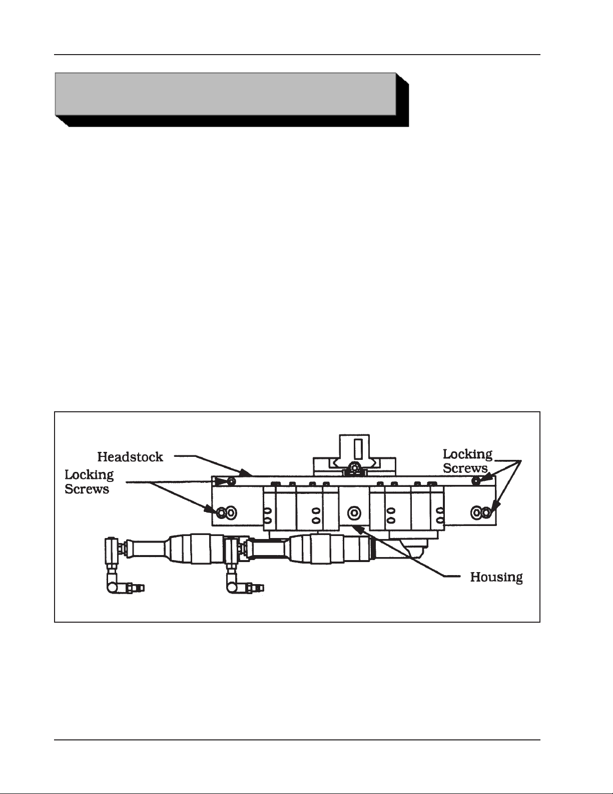
Locking Screw Locations
Rotate the Headstock by hand until the split-lines of the Headstock match the
split-lines of the Housing.
Fasten the two Lock Blocks from the Headstock to the Thrust Plate on each half of
the Clamshell.
18
92-0220 : Rev. 131230
 Loading...