

Page 1
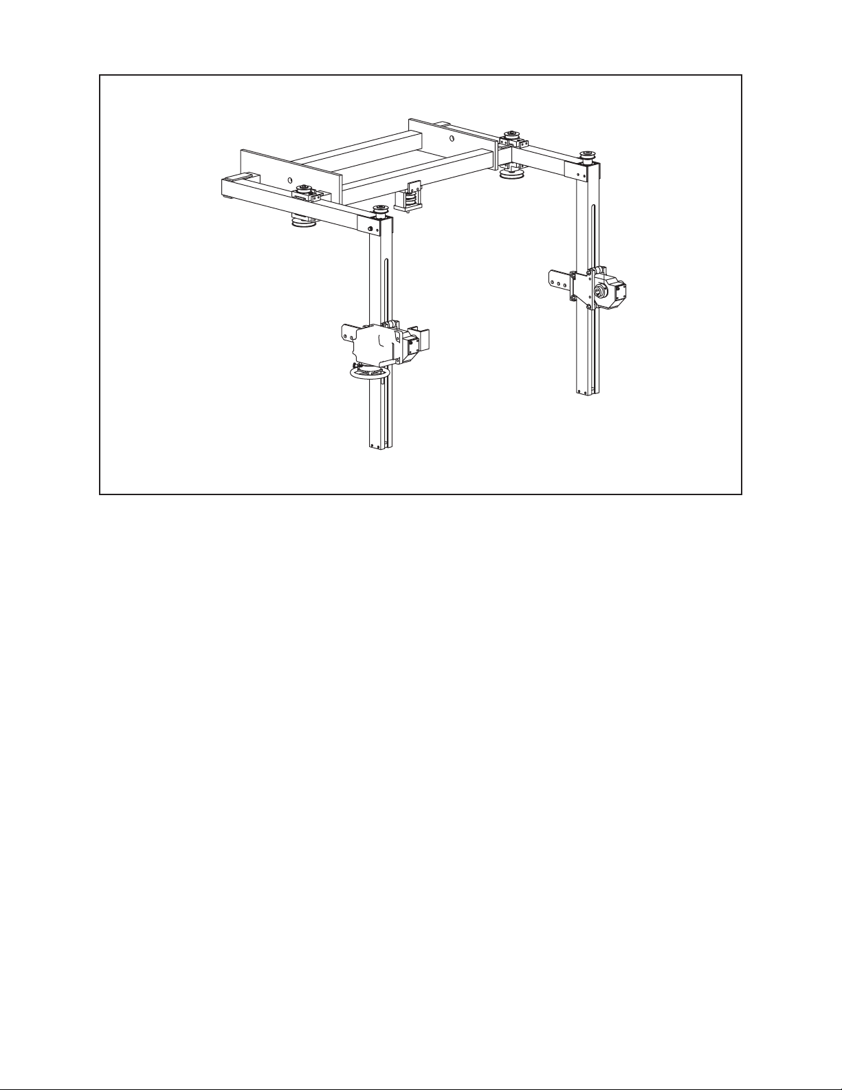
TABLE OF CONTENTS
CUSTOMER MESSAGE Inside Front Cover
SAFETY PRECAUTIONS 3
GENERAL DESCRIPTION 6
92-1058 Orig. 021204
Model 230B Lifting Frame
SPECIFICATIONS 8
MAINTENANCE 9
INSTALLATION 10
OPERATION 11
TROUBLE SHOOTING 12
ILLUSTRATED PARTS BREAKDOWN 14
TOOL BIT RESHARPENING POLICY Inside Back Cover
WARRANTY INFORMATION Inside Back Cover
Page 2

Copyright 2002
Proprietary property of TRI TOOL Inc.
No reproduction, use, or duplication of the information
shown hereon is permitted without the express written
consent of TRI TOOL Inc.
Page 3
SAFETY PRECAUTIONS
IN GENERAL
When using rotating head cutting equipment, basic safety precautions should always
be followed to reduce the risk of personal injury.
Operate this tool only in accordance with specific operating instructions.
Do not override the deadman switch on the power unit. Locking down, ob-
WARNING:
DRESS CONSIDERATIONS
structing, or in any way defeating the deadman switch on the power drive unit
may result in serious injury.
Model 230B Lifting Frame
Use standard safety equipment. Hard hats, safety shoes, safety harnesses, protective clothes, and other safety devices should always be used when appropriate.
Use safety glasses. Do not operate cutting tools without eye protection.
Dress properly. Do not wear loose clothing or jewelry. They can be caught in rotating and moving parts. Avoid slippery floors or wear nonskid footwear. If you have
long hair, wear protective hair covering to contain it.
WORK AREA
Keep the work area clean. Cluttered work areas and benches invite injuries.
Consider the work area environment. Keep the area well lit. Keep electrical cords,
cables, rags, rigging straps, and etc. clear of rotating equipment. Do not use powercutting tools in the presence of flammable liquids and gasses.
Keep visitors away. Do not let visitors or untrained personnel at or near operating
tools. Enforce eye protection requirements for all observers.
Do not over reach. Keep proper footing at all times.
Stay alert. Watch what you are doing. Use common sense. Do not operate tools
when you are tired.
92-1052 : Orig. 021204
3
Page 4

TRI TOOL INC.
TOOL CARE
Maintain tools with care. Keep tools in good operating condition. Sharp tool bits
perform better and safer than dull tool bits. Well maintained tools function properly
when needed.
Check for damaged parts. If a tool has malfunctioned, been dropped or hit, it must
be checked for damage. Run no-load tests and feed function checks. Do a complete visual inspection.
Electric motors. Use only with proper AC voltage power sources and observe all
normal electric shock hazard procedures.
Do not abuse power and control cords. Pulling or running over cords and cables
can result in electrical shock hazards and malfunctions. Keep control and power
cords out of all cutting fluids and water.
Hydraulic drives. Observe proper procedures for electrically driven power sources.
Avoid damage to hydraulic lines. Keep quick-disconnects clean. Grit contamination
causes malfunctions.
Air tools. Check the exhaust muffler. Broken or damaged mufflers can restrict air
flow or cause excessive noise. Use air motors only with a filtered, lubricated and
regulated air supply. Dirty air, low-pressure air or over pressure air will cause malfunctions, including delayed starting.
AREA EQUIPMENT
Secure work. Whenever possible use clamps, vises, chains and straps to secure
pipe.
Make sure the tool is secured; it is safer to have both hands free to operate the tool.
TOOL USE
Us the right tool and tool bit for the job. Do not use a tool, which is incorrect for the
job you are doing.
Keep the tool bits fully engaged in the tool bit holders. Loose bits are a safety hazard.
4
92-1058 : Orig. 021204
Page 5

Model 230B Lifting Frame
Disconnect power supply during setup and maintenance. Use all ‘Stop’ or Shut off’
features available when changing or adjusting tool bits, maintaining the tool, or when
the tool is not in use.
Remove adjusting keys and wrenches before applying power to the equipment.
Develop a habit of checking the tool before turning it on to make sure that all keys
and wrenches have been removed.
Do not force tools. Tools and tool bits function better and safer when used at the
feed and speed rate for which they were designed.
Do not reach into rotating equipment. Do not reach into the rotating head stock to
clear chips, to make adjustments, or to check surface finish. A machine designed to
cut steel will not stop for a hand or an arm.
Handle chips with care. Chips have very sharp edges and are hot. Do not try to pull
chips apart with are hands; they are very tough.
Avoid unintentional starts. Do not carry or handle tools with your hand on the operating switches or levers. Do not lay the tool down in a manner that will start the
drive. Do not allow the tool to flip around or move when adjusting or changing tool
bits.
Store idle tools properly. Disconnect tools from the power source and store in a safe
place. Remove tool bits for safe handling of the tool.
92-1052 : Orig. 021204
5
Page 6

TRI TOOL INC.
GENERAL DESCRIPTION
This lifting device attaches to the crane in the welding station of the J-lay tower on
the Heerema vessel Balder. The lifting device enables either the pipe cut-off
clamshell tool or the end preparation tool (230B) to be easily lifted and positioned on
the pipe in the tower. The lifting motion is powered by a hand-held drive that has on/
off and up/down control. This device attaches to the crane in a way that keeps the
orientation of the vertical positioners always aligned with the crane and thus the axis
of pipe. The lifting device is attached to the crane by pinning to two of the padeyes
on the bottom of the crane. The pipe cut-off clamshell tool is attached to the lifting
device with two slings. These slings attach to two lifting rings on the clamshell tool
and to plates with four attachment holes on the vertical positioners. The end preparation tool attaches to the lifting device with two pillow blocks. The orientation of the
end preparation tool is adjustable to allow operation on the pipe end coming through
either the floor or the ceiling of the welding station. This lifting device is made up of
three major assemblies, the crane attachment assembly, the yoke assembly, and the
vertical positioner assembly.
Crane Attachment Assembly
The crane attachment assembly secures the lifting device to the crane and maintains the device in alignment with the crane. As the crane stays in alignment with the
pipe, the lifting device and end preparation tool will also be in alignment with the
pipe. Pins are used to secure the two end plates of the crane attachment assembly
to padeyes on the crane. Structural members connect the two end plates creating a
secure foundation for the lifting device. The top surface of the forward end plate is in
close proximity to the bottom surface of the crane. This keeps the assembly aligned
with the crane as the J-lay tower angle is changed.
Yoke Assembly
The yoke assembly provides the structural connection between the vertical
positioner and the crane attachment assembly. This assembly is sized to allow the
lifting device to accommodate either the pipe cut-off tool or the end preparation tool.
This assembly also contains the power transmission components that connect the
vertical position to the vertical positioner drive.
6
92-1058 : Orig. 021204
Page 7

Vertical Positioner
The vertical positioner consists of two components each of which contains an acme
screw and the associated nuts, bearings, and power transmission hardware to
securely lift and position either the pipe cut-off clamshell or the end preparation tool.
A series of holes allow adjustment in attaching the slings to the pipe cut-off
clamshell. Spring-centering pillow blocks provide a compliant attachment of the end
preparation tool to the vertical positioner, allowing the tool to be easily aligned with
the axis of the pipe. A worm gear driven mechanism is used to provide control of the
orientation of the end preparation tool for use on pipes coming through either the
ceiling or the floor.
Model 230B Lifting Frame
92-1052 : Orig. 021204
7
Page 8

TRI TOOL INC.
Lifting Capacity: 1600 lbs
Range of Motion: 42"
Unloaded Speed of Travel:
High Speed (No Load): 50 in/min
Low Speed (No Load): 13 in/min
Crane Attachment Hole Size: 1.38" DIA
Distance Between Crane Attachment Holes: 57"
SPECIFICATIONS
Clamshell Attachment Hole Size: .78" DIA
Motor Power Requirements: 120 VAC, 60 Hz, 16.3 A
maximum
8
92-1058 : Orig. 021204
Page 9

Cleaning
The lifting screw surfaces should be inspected periodically for contamination from
metal chips and debris. Any contamination should be removed immediately to prevent damage to the screw and nut.
Lubrication
The lifting screw must always be kept well lubricated with a quality EP grease such
as Chevron Ultra Duty Grease EP, NLGI 2. The gearbox of the 230B rotator mechanism must be maintained full of Mobil SHC 634 Bearing and Gear Oil, ISO VG 460,
or equivalent.
Model 230B Lifting Frame
MAINTENANCE
Belt Tension
Belt tension should be checked periodically and adjusted as needed to maintain
about a 1/2" belt deflection when 10 pounds of force is applied mid-way between the
pulleys. When adjusting the belt tension it is important to adjust both the upper and
lower tensioning bolts equally to keep the pulley shaft perpendicular to the frame.
92-1052 : Orig. 021204
9
Page 10

TRI TOOL INC.
Attach the lifting device to the overhead crane using the two 1.38 inch diameter
holes in the frame of the lifting device.
230B attachment: Remove the two adjustable length square tubes from the frame of
the 230B. Insert the 2 inch diameter pins welded to each of the square tubes in to
the two sleeves in the lifting device pillow blocks. One of the square tubes will engage the yolk attached to the rotator mechanism. Lift the 230B and install the frame
over the two adjustable length square tubes. Position the 230B so that its center-ofgravity is at the 2 inch diameter pins in the pillow block sleeves. Install the pins that
secure the square tubes to the 230B frame.
Clamshell attachment: The clamshell is attached to the lifting device carriage using
short slings and shackles. These connect between the lifting eyes on the clamshell
and the holes in the 11.5 x 4 x ½ inch thick plates on the lifting device carriage.
INSTALLATION
10
92-1058 : Orig. 021204
Page 11

Model 230B Lifting Frame
OPERATION
A two-speed, reversible, hand-held drill motor is used power the lifting device. Attached to the drill motor is a 3’ extension with a 1/2" deep-socket. This assembly is
held by the operator, who uses the on/off trigger switch, forward/reverse switch, and
low/high-speed switch to control the motion of the lifting device. A hand crank is
attached to the rotator mechanism to enable changing the orientation of the 230B. A
swing-energized locking pin holds the hand crank in position. The pin must be
manually pulled out to disengage the lock, allowing the hand crank to be turned.
CAUTION: The locking pin must be engaged whenever the hand crank is not in use
to prevent uncontrolled rotation of the 230B.
To perform a lifting or lowering operation, the operator sets the drill motor to the
desired speed and direction and engages the 1/2" socket over the 1/2" hex protruding from the bottom of the center pulley assembly. The drill motor is then energized,
causing the pulleys and timing belts to rotate the two acme screws, resulting in lifting
carriage motion. CAUTION: The lifting carriage should not be allowed to run to its
hard-stops at either end of its travel. Carriage motion should be stopped once it
reaches the area marked with caution tape.
92-1052 : Orig. 021204
11
Page 12

TRI TOOL INC.
TROUBLE SHOOTING
Problem: The Tool Bit Chatters
The tool bit is loose or overextended.
The tool bit is damaged.
The tool holder is too loose in the slides.
The cutting speed is too fast.
The clamping pads are loose on the pipe or tube.
Cutting fluid is required.
The main bearing pre-load is loose.
Problem: There is excessive Tool Bit wear
The pipe or tube material is too hard or abrasive.
The cutting speed is too fast.
Cutting fluid is required.
A dull Tool Bit is causing surface hardening conditions (Stainless pipe or
tubing).
There is scale or other foreign matter on the pipe or tube, which is dulling the
tool bit at the start of the cut.
The tool bit is incorrect for the material being cut.
Problem: The surface finish is rough
The tool bit is dull, chipped, etc.
Metal build-up on the cutting edge of the tool bit is creating a false cutting
edge.
Cutting fluid is required.
Problem: The tool holder is not feeding
12
The feed pin is broken or out of position.
The feed sprocket shear pin is broken.
The feed screw is stripped.
The feed nut is stripped.
The slide rails are too tight.
92-1058 : Orig. 021204
Page 13

Problem: There is a loss of air power
The air supply pressure is too low.
The air filter is plugged.
The air line size is insufficient.
The air line is too long.
Problem: There is a loss of hydraulic power
The hydraulic supply pressure is too low.
The hydraulic filter is plugged.
The hydraulic line size is insufficient.
The hydraulic line is too long.
Problem: The tool bit will not reach the work
Model 230B Lifting Frame
Incorrect tool blocks are installed for the size of the pipe or tube being
worked on.
Incorrect tool bit is installed.
Problem: The hydraulic motor will not start
The hydraulic power supply is shut off.
The hydraulic motor is damaged and will not run free.
92-1052 : Orig. 021204
13
Page 14
TRI TOOL INC.
ILLUSTRATED PARTS BREAKDOWN
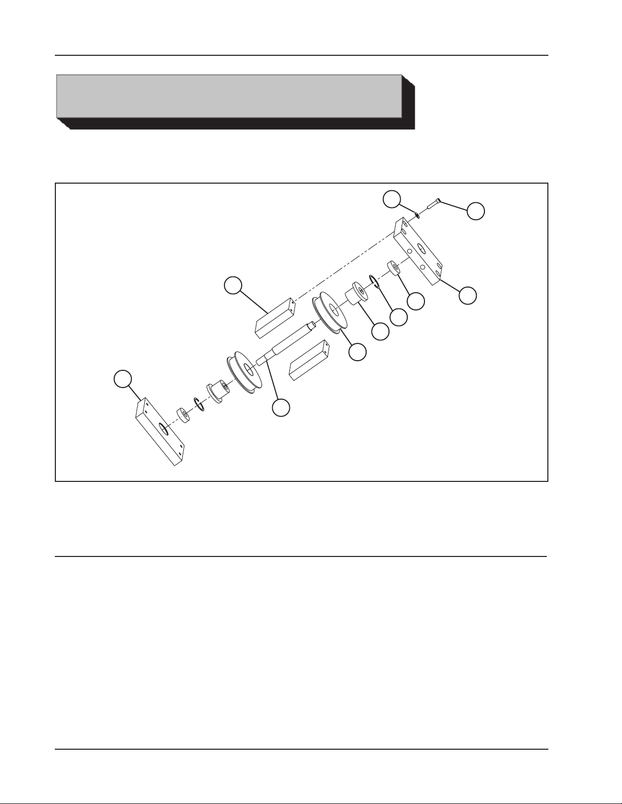
CENTER PULLEY ASSEMBLY
2
9
10
8
7
6
1
5
3
4
Parts List, Center Pulley Assembly
Item Part
No. No. Description Qty
1. 48-1652 BLOCK, BASE PLATE 1
2. 24-2131 PLATE, SIDE, PULLEY ASSY 2
3. 48-1651 BLOCK, BASE PLATE, WITHOUT HOLES 1
4. 20-0918 SHAFT, CENTER PULLEY 1
5. 6495K318 PULLEY, TIMING BELT, 3/8" PITCH, 32 TOOTH 2
6. 6086K13 BUSHING, SDS, 3/4" BORE 2
7. 98409A233 RETAINING RING 2
8. 202PP BEARING, RADIAL 2
9. 90107A029 WASHER, 1/4", SST 8
10. 92196A543 SHCS, 1/4-20 X 1 1/8, SST 8
14
92-1058 : Orig. 021204
Page 15
Model 230B Lifting Frame
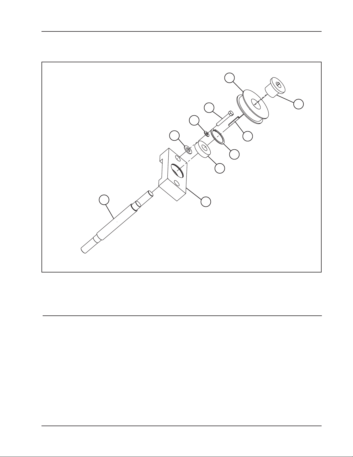
SIDE PULLEY ASSEMBLY
4
6
8
10
9
2
1
5
7
3
Parts List, Side Pulley Assembly
Item Part
No. No. Description Qty
1. 48-1650 BLOCK, BOTTOM, PULLEY ASSY 1
2. 20-0919 SHAFT, PULLEY 1
3. 1610-3/4" BUSHING, TAPERED, 3/4" BORE 1
4. TB30L075 PULLEY, TIMING BELT, 3/8 PITCH, 30 TOOTH 1
5. 31-0221 KEY, 3/16" SQ X 1.5" L 1
6. 93190A591 HHCS, 5/16-18 X 2, SST 2
7. 98409A244 RETAINING RING 1
8. 90107A030 WASHER, 5/16", SST 2
9. 204PP BEARING, RADIAL 1
10. 91950A033 WASHER, 1/2", SST 2
92-1058 : Orig. 021204
15
Page 16
TRI TOOL INC.
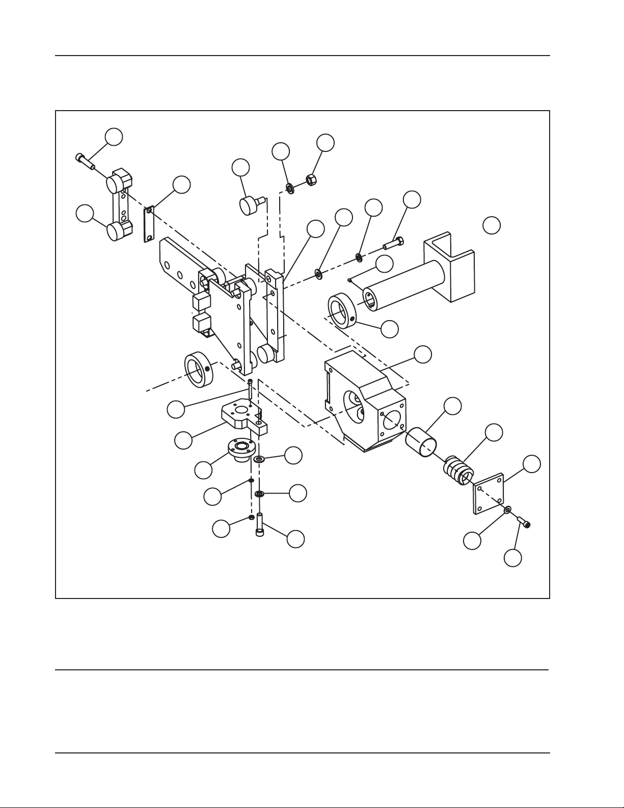
CARRIAGE ASSEMBLY (1 OF 2)
16
13
12
15
5
A
28
6
25
7
14
23
22
1
24
3
42
11
2
17
18
19
29
30
26
27
20
21
Parts List, Carriage Assembly
Item Part
No. No. Description Qty
1. 71-0053 FRAME, CARRIAGE 1
2. 48-1646 BLOCK, PILLOW, MAIN BODY 1
3. 14-0098 SHAFT, ASSEMBLY, LIFTING FRAME ROTATOR 1
4. HV30-7B-15 SPEED REDUCER 1
16
92-1058 : Orig. 021204
Page 17
Model 230B Lifting Frame
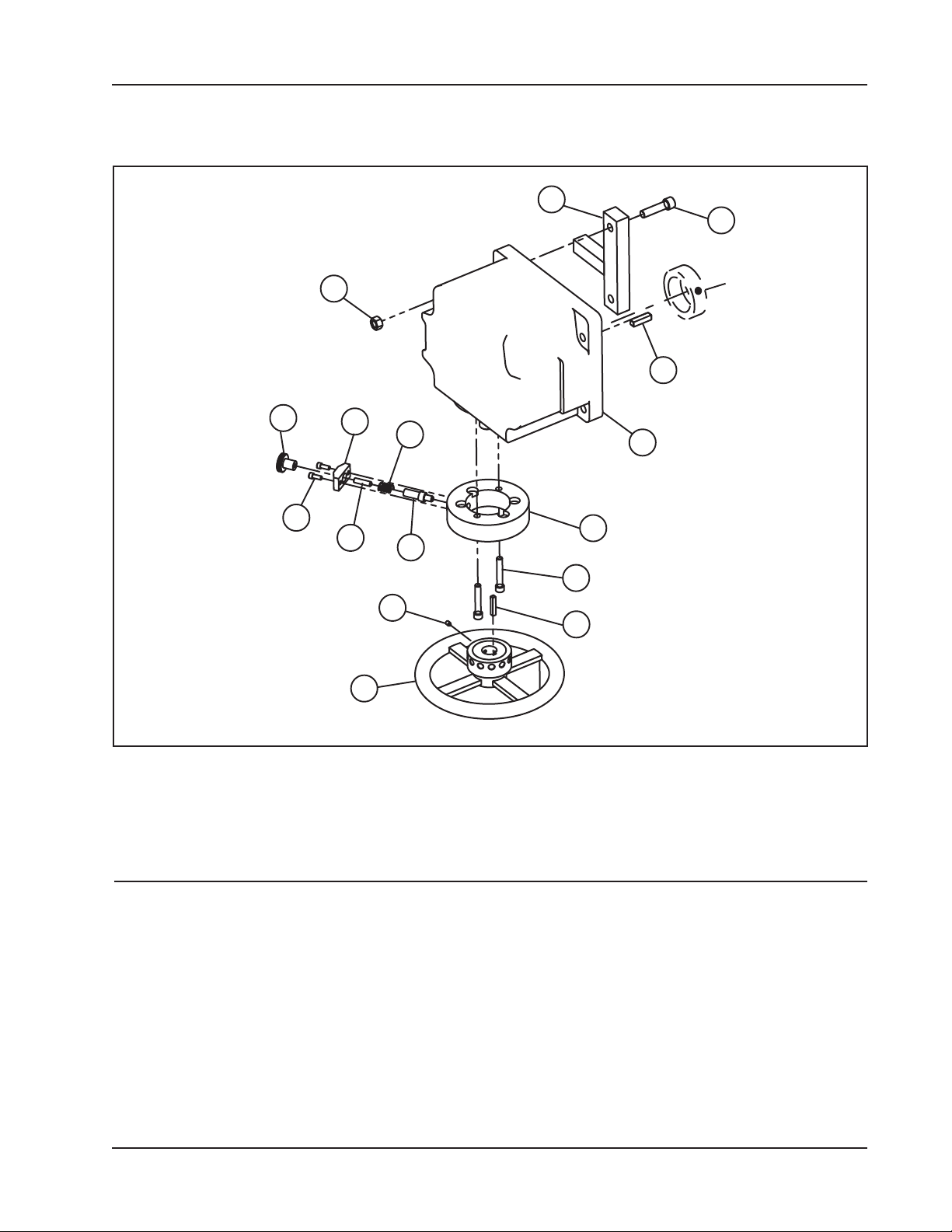
CARRIAGE ASSEMBLY (2 OF 2)
10
31
39
38
32
37
36
REF TO A
33
35
8
34
40
42
41
9
4
Parts List, Carriage Assembly Continued
Item Part
No. No. Description Qty
5. 48-1654 BLOCK, ROLLER CARRAGE 2
6. 24-2126 PLATE, ACME, NUT CARRIER 1
7. 35-0661 NUT, ACME 1
8. 47-1544 BRACKET, WHEEL LOCK 1
9. 61-0165 WHEEL, ROTATION 1
10. 71-0054 FRAME, ANTI-ROTATION WELDMENT 1
11. 6432K47 COLLAR 2
12. 3649K21 ROLLER, TRACK, URETHANE COATED 8
13. 92147K035 LOCKWASHER, 5/8", SST 8
92-1058 : Orig. 021204
17
Page 18

TRI TOOL INC.
Parts List, Carriage Assembly Continued
Item Part
No. No. Description Qty
14. 94804A355 NUT, 5/8-18, SST 8
15. 24-2140 PLATE, SHIM, ROLLER CARRIER 2
16. 33-0109 SCREW, CAP, 1/2-13 X 2" 4
17. 1878K58 DIE SPRING CAGE 3
18. 9295K93 DIE SPRING 3
19. 24-2127 PLATE, COVER, SPRING DIE 3
20. 91950A031 WASHER, 3/8", SST 12
21. 33-0072 SCREW, CAP, 3/8-16 X 1 1/4" 12
22. 91950A033 WASHER, 1/2", SST 4
23. 92147A033 LOCKWASHER, 1/2", SST 4
24. 92186A718 HHCS, 1/2-13 X 1.75, SST 4
25. 92147A033 LOCKWASHER, 1/2", SST 1
26. 92186A718 HHCS, 1/2-13 X 1.75, SST 1
27. 33-0109 SCREW, CAP, 1/2-13 X 2" 1
28. 33-0046 SCREW, CAP, 1/4-20 X 2" 4
29. 92147A029 LOCKWASHER, 1/4", SST 4
30. 35-0017 NUT, HEX, 1/4-20 4
31. 33-0109 SCREW, CAP, 1/2-13 X 2" 2
32. 35-0021 NUT, HEX, 1/2-13 2
33. 31-0067 KEY, 3/8" SQ X 1.5 1
34. 32-0656 PIN, WHEEL LOCK 1
35. 40-0267 SPRING, COMPRESSION, .60"ODX1" LG X .045WD 1
36. 33-0521 SCREW, SET, 5/16-18 X 1 1/4, CUP PT 1
37. 48-1206 BLOCK, PIN RETAINING 1
38. 33-0039 SCREW, CAP,1/4-20 X 5/8" 2
39. 42-0193 KNOB, KNURLED, SS 1
40. 33-0240 SCREW, CAP, 3/8-24 X 2 1/4" 2
41. 31-0074 KEY, 1/4" SQ X 1.5 1
42. 33-1458 SCREW, SET, MOD., 1/4-20 X 3/8, BRASS TIP 6
18
92-1058 : Orig. 021204
Page 19
Model 230B Lifting Frame
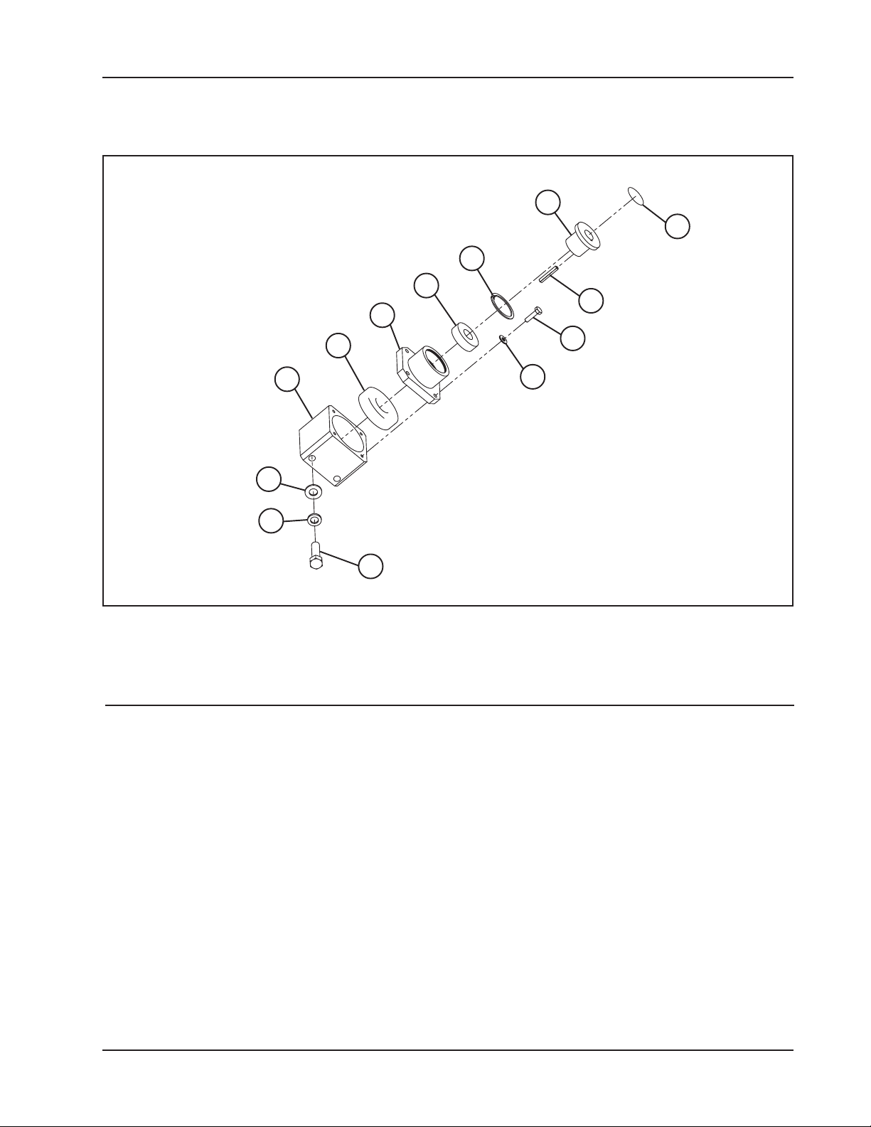
SCREW SUPPORT ASSEMBLY
6
5
4
3
2
9
7
8
1
13
12
11
10
Parts List, Screw Support Assembly
Item Part
No. No. Description Qty
1. 48-1645 BLOCK, UPPER BEARING SUPPORT 1
2. 7306WN BEARING, ANGULAR CONTACT 1
3. 48-1644 BLOCK, UPPER, BEARING COVER 1
4. 204PP BEARING, RADIAL BALL 1
5. 98409A244 RETAINING RING 1
6. 1610-3/4" BUSHING, TAPERED, 3/4" BORE 1
7. TB30L075 PULLEY, TIMING BELT, 3/8 PITCH, 30 TOOTH 1
8. 31-0221 KEY, 3/6" SQ X 1.5 L 1
9. 93190A542 HHCS, 1/4-20 X 1 L, SST 4
10. 90107A029 WASHER, 1/4", SST 4
11. 92186A718 HHCS, 1/2-13 X 1.75 L, SST 4
12. 92147A033 LOCKWASHER, 1/2", SST 4
13. 91950A033 WASHER, 1/2", SST 4
92-1058 : Orig. 021204
19
 Loading...