

Page 1
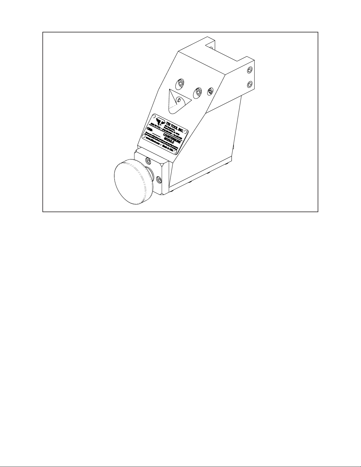
TABLE OF CONTENTS
CUSTOMER MESSAGE Inside Front Cover
SAFETY PRECAUTIONS 3
GENERAL DESCRIPTION 6
92-0177 Rev. 140226
Model CBM-2, Counterbore Module
SPECIFICATIONS 7
MAINTENANCE 9
OPERATION 10
CUTTING SPEEDS 12
TOOL BITS 13
TROUBLE SHOOTING 14
ILLUSTRATED PARTS BREAKDOWN 16
TOOL BIT RESHARPENING POLICY Inside Back Cover
WARRANTY INFORMATION Inside Back Cover
Page 2

Copyright 2014
Proprietary property of TRI TOOL INC.
No reproduction, use, or duplication of the information
shown hereon is permitted without the express written
consent of TRI TOOL INC.
Page 3
SAFETY PRECAUTIONS
IN GENERAL
When using rotating head cutting equipment, basic safety precautions should always
be followed to reduce the risk of personal injury.
Operate this tool only in accordance with specic operating instructions.
Do not override the deadman switch on the power unit. Locking down, ob-
WARNING:
DRESS CONSIDERATIONS
structing, or in any way defeating the deadman switch on the power drive unit
may result in serious injury.
Model CBM-2, Counterbore Module
Use standard safety equipment. Hard hats, safety shoes, safety harnesses, protective clothes, and other safety devices should always be used when appropriate.
Use safety glasses. Do not operate cutting tools without eye protection.
Dress properly. Do not wear loose clothing or jewelry. They can be caught in rotat-
ing and moving parts. Avoid slippery oors or wear nonskid footwear. If you have
long hair, wear protective hair covering to contain it.
WORK AREA
Keep the work area clean. Keep the area well lit. Keep electrical cords, cables,
rags, rigging straps, and etc. clear of rotating equipment. Do not use power-cutting
tools in the presence of ammable liquids and gasses.
Keep visitors away. Do not let visitors or untrained personnel at or near operating
tools. Enforce eye protection requirements for all observers.
Do not over reach. Keep proper footing at all times.
Stay alert. Watch what you are doing. Use common sense. Do not operate tools
when you are tired.
92-0177 : Rev. 140226
3
Page 4

TRI TOOL INC.
TOOL CARE
Maintain tools with care. Keep tools in good operating condition. Sharp tool bits
perform better and safer than dull tool bits. Well maintained tools function properly
when needed.
Check for damaged parts. If a tool has malfunctioned, been dropped or hit, it must
be checked for damage. Run no-load tests and feed function checks. Do a complete visual inspection.
Electric motors. Use only with proper AC voltage power sources and observe all
normal electric shock hazard procedures.
Do not abuse power and control cords. Pulling or running over cords and cables can
result in electrical shock hazards and malfunctions. Keep control and power cords
out of all cutting uids and water.
Hydraulic drives. Observe proper procedures for electrically driven power sources.
Avoid damage to hydraulic lines. Keep quick-disconnects clean. Grit contamination
causes malfunctions.
Air tools. Check the exhaust mufer. Broken or damaged mufers can restrict air
ow or cause excessive noise. Use air motors only with a ltered, lubricated and
regulated air supply. Dirty air, low-pressure air or over pressure air will cause malfunctions, including delayed starting.
AREA EQUIPMENT
Secure work. Whenever possible use clamps, vises, chains and straps to secure
pipe.
Make sure the tool is secured; it is safer to have both hands free to operate the tool.
TOOL USE
Use the right tool and tool bit for the job. Do not use a tool, which is incorrect for the
job you are doing.
Keep the tool bits fully engaged in the tool bit holders. Loose bits are a safety
hazard.
4
92-0177 Rev. 140226
Page 5

Model CBM-2, Counterbore Module
Disconnect power supply during setup and maintenance. Use all 'Stop' or 'Shut off'
features available when changing or adjusting tool bits, maintaining the tool, or when
the tool is not in use.
Remove adjusting keys and wrenches before applying power to the equipment. Develop a habit of checking the tool before turning it on to make sure that all keys and
wrenches have been removed.
Do not force tools. Tools and tool bits function better and safer when used at the
feed and speed rate for which they were designed.
Do not reach into rotating equipment. Do not reach into the rotating head stock to
clear chips, to make adjustments, or to check surface nish. A machine designed to
cut steel will not stop for a hand or an arm.
Handle chips with care. Chips have very sharp edges and are hot. Do not try to pull
chips apart with your hands; they are very tough.
Avoid unintentional starts. Do not carry or handle tools with your hand on the operating switches or levers. Do not lay the tool down in a manner that will start the
drive. Do not allow the tool to ip around or move when adjusting or changing tool
bits.
Store idle tools properly. Disconnect tools from the power source and store in a safe
place. Remove tool bits for safe handling of the tool.
92-0177 : Rev. 140226
5
Page 6

TRI TOOL INC.
GENERAL DESCRIPTION
The C’bore Module Kit is a mechanical accessory for the Model 604SB through
612SB Clamshell.
The C’bore Module provides the capability to counterbore pipe after an in-line spool,
valve or tting has been removed.
The C’bore Module is mounted directly to the Clamshell.
No repositioning or modication of the Clamshell is necessary after the in-line spool
has been removed.
The C’bore Module features a manual “easy grip” axial feed and innitely adjustable
radial positioning.
The C’bore Module uses Form Tooling Tool Bits that are available in various
standard congurations.
6
92-0177 Rev. 140226
Page 7
Model CBM-2, Counterbore Module
SPECIFICATIONS
Weight 5.6 lbs. (2.6 Kg)
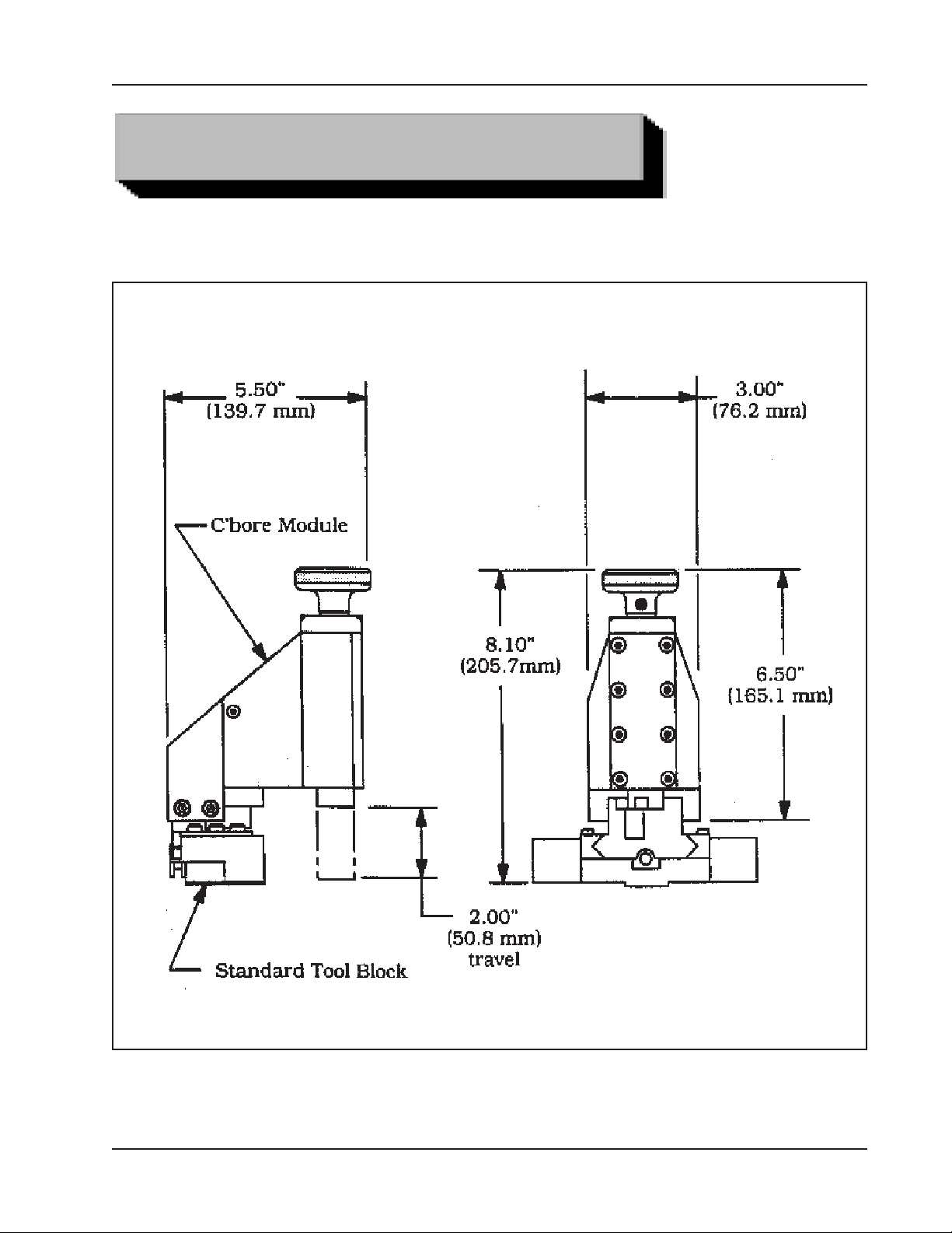
Envelope, Model CBM-2, Counterbore Module
92-0177 : Rev. 140226
7
Page 8

TRI TOOL INC.
Basic Pipe Sizes
Equal to the full range of the Clamshell to which the C’bore Module has been
mounted.
Approximately 3” pipe through 12” pipe, all schedules.
C’bore Depth
Up to 2.00” (50.8 mm) plus lead-out.
Clearances
Rotating Parts DIA
Rotating DIA of the Clamshell
Length
8.10” (205.7 mm) from the face of the Clamshell.
Axial Feed Length
2.00” (50.8 mm)
Axial Feed Rate
.031” (.78 mm) per revolution.
8
92-0177 Rev. 140226
Page 9

DAILY
Model CBM-2, Counterbore Module
MAINTENANCE
All components should be cleaned and coated with a light lm of oil prior to storage.
Use a clean, non-detergent oil, preferable SAE 10 (90 SSU or lighter) or oil which is
specied for the air motor.
If the C’bore Module is operated in such a way that the Module collects chips
or debris near the tool holder, the C’bore Module should be cleaned after
each cutting operation.
Wipe the unit down and spray with rust preventative under severe humidity
conditions.
Visually inspect for loose screws, missing bolts, or damage due to impact.
Tighten or replace screws or other parts as required.
Contact Tri Tool Inc. if a major repair is required.
MONTHLY
Thoroughly clean and lubricate the Feed Screw and the Boring Bar.
Feed the Boring Bar out of the Tool Bracket.
With a clean, dry rag, thoroughly wipe down the Boring Bar and the Feed Screw. Be
sure that all old lubrication, chips, and dirt are completely removed.
Lubricate the Feed Screw and Boring Bar with a light machine oil.
Reassemble the Boring Bar into the Tool Bracket.
92-0177 : Rev. 140226
9
Page 10
TRI TOOL INC.
Read the operating instructions carefully before attempting to operate the C’bore
Module.
Use eye protection at all times when operating the C’bore Module.
Install the Clamshell on the pipe and remove the in-line spool, tting etc. as described in the appropriate Clamshell operating instructions.
Refer to the Operator’s Manual for operation of the 600SB Series Clamshell,
which is to be used.
Slide the Mounting Adapter into the Tool Holder. Tighten all mounting screws.
OPERATION
CONFIGURING THE COUNTERBORE MODULE
Select the appropriate Tool Bit. Refer to the ‘Tool Bits' section.
Use of dull or improperly designed Tool Bits or Tool Bits not manufactured by
WARNING:
Install the Tool Bit in the Boring Bar. Be sure the cutting edge lies along the radial
centerline in the direction of rotation.
Adjust the counterbore diameter.
Radially adjust the Feed Tube using the Feed Sprocket.
Tri Tool Inc. may result in poor performance and may constitute abuse of this
machine and therefore voids the Tri Tool Inc. factory warranty.
MACHINING SEQUENCE
Check to insure that the Tool Bits are clear of the pipe and that the Clamshell Feed
Pin is retracted.
10
Slowly rotate the clamshell to insure that the Form Tooling Bit clears the pipe.
Increase the Clamshell RPM to cutting speed. Refer to the section on ‘Cutting
Speeds’.
To feed the Tool Bit in, hold the Feed Knob.
92-0177 Rev. 140226
Page 11

Model CBM-2, Counterbore Module
WARNING:
WARNING:
When the counterbore is nished, release the Feed Knob and allow the Clamshell to
rotate 2 or 3 times to release the chip.
Retract the Tool Bit.
Remove the C’bore Module from the Clamshell.
Remove the Clamshell from the pipe as described in the appropriate Clamshell
instruction manual.
Do not use a wrench or lever to obtain extra holding strength.
Do not force the feed.
If the feed pressure builds up too high, release the knob for 2 or 3 revolutions
before continuing.
92-0177 : Rev. 140226
11
Page 12
TRI TOOL INC.
CUTTING SPEEDS AND FEEDS
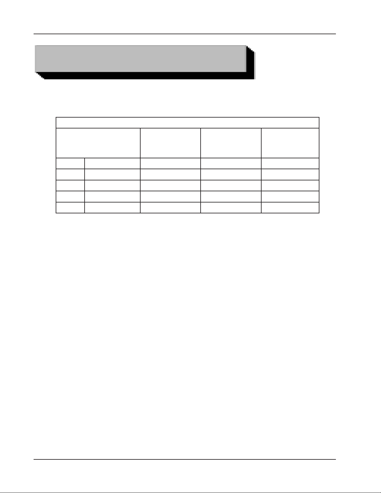
The chart shows RPM to obtain specied Tool Bit surface cutting speed on the
surface of the pipe.
CUTTING SPEEDS APPROXIMATE
RPM for
DIA
12.00" 304.8 mm 5 7 8
10.00" 254.0 mm 6 8 10
8.00" 203.2 mm 8 10 12
6.00" 152.4 mm 11 13 16
4.00" 101.3 mm 16 20 24
Use 200 surface inches per minute (508 surface centimeters per minute) for:
Stainless steels in general when no coolant is allowed, all heavy-wall tube
and some of the chrome/molybdenum steels.
Use 250 surface inches per minute (635 surface centimeters per minute) for:
Mild steels and some thin wall stainless steels when coolants are permitted
and applied.
200 in/min
(508 cm/min)
RPM for
250 in/min
(635 cm/min)
RPM for
300 in/min
(762 cm/min)
12
Use 300 surface inches per minute (762 surface centimeters per minute) for:
Aluminum and thin-wall mild steel and tube with coolants.
92-0177 Rev. 140226
Page 13
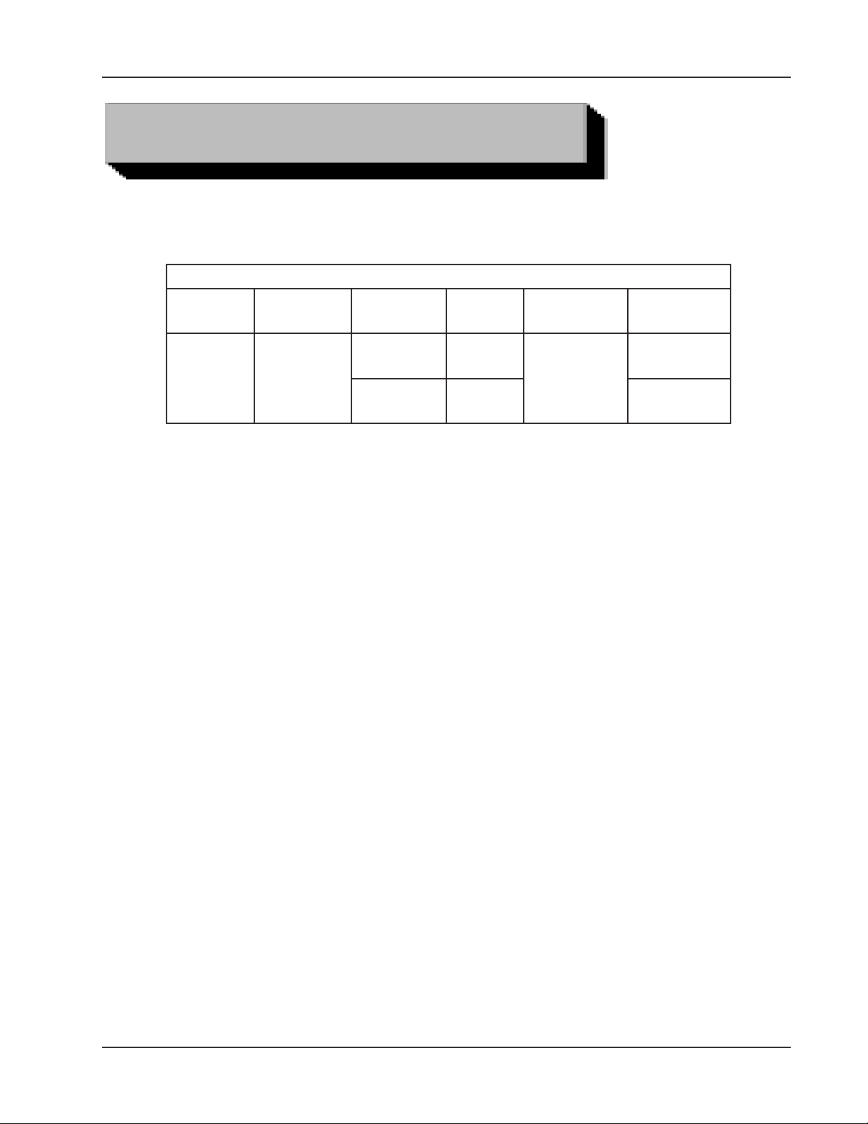
TOOL BITS
C'bore
Angle
14.5° C S , S S
Pipe or
Tube Mat'l
Tool Bits
Tool Bit
Length
1.38"
(35.1 mm)
2.25"
(57.2 mm)
Model CBM-2, Counterbore Module
Double
End
NO
YES 99-2670
Radius
.070"
(1.8 mm)
C'bore Tool
Bit P/N
99-2669
92-0177 : Rev. 140226
13
Page 14

TRI TOOL INC.
TROUBLE SHOOTING
Problem: The Tool Bit Chatters
The tool bit is loose or overextended.
The tool bit is damaged.
The tool holder is too loose in the slides.
The cutting speed is too fast.
The clamping pads are loose on the pipe or tube.
Cutting uid is required.
The main bearing pre-load is loose.
Problem: There's Excessive Tool Bit Wear
The pipe or tube material is too hard or abrasive.
The cutting speed is too fast.
Cutting uid is required.
A dull Tool Bit is causing surface hardening conditions (Stainless pipe or
tubing).
There is scale or other foreign matter on the pipe or tube, which is dulling the
tool bit at the start of the cut.
The tool bit is incorrect for the material being cut.
Problem: The Surface Finish is Rough
The tool bit is dull, chipped, etc.
Metal build-up on the cutting edge of the tool bit creates a false cutting edge.
Cutting uid is required.
Problem: The Tool Holder is Not Feeding
The feed pin is broken or out of position.
The feed sprocket shear pin is broken.
The feed screw is stripped.
The feed nut is stripped.
The slide rails are too tight.
14
92-0177 Rev. 140226
Page 15

Model CBM-2, Counterbore Module
Problem: There's a Loss of Air Power
The air supply pressure is too low.
The air lter is plugged.
The air line size is insufcient.
The air line is too long.
Problem: There's a Loss of Hydraulic Power
The hydraulic supply pressure is too low.
The hydraulic lter is plugged.
The hydraulic line size is insufcient.
The hydraulic line is too long.
Problem: The Tool Bit Will Not Reach the Work
Incorrect tool blocks are installed for the size of the pipe or tube being
worked on.
Incorrect tool bit is installed.
Problem: The Hydraulic Motor Will Not Start
The hydraulic power supply is shut off.
The hydraulic motor is damaged and will not run free.
92-0177 : Rev. 140226
15
Page 16
TRI TOOL INC.
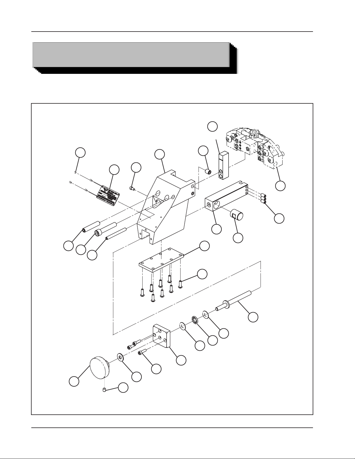
ILLUSTRATED PARTS BREAKDOWN
MODEL CBM-2, COUNTERBORE MODULE (P/N 82-0047)
22
REF.
11
12
6
14
20
4
15
10
23
REF.
9
21
18
2
7
13
16
19
17
3
17
1
5
16
8
92-0177 Rev. 140226
Page 17

Model CBM-2, Counterbore Module
Parts List, Model CBM-2, Counterbore Module (P/N 82-0047)
Item Part
No. No. Description Qty
1 24-0693 PLATE, TOP 1
2 24-0694 PLATE, COVER 1
3 29-0190 BEARING, THRUST, 5/16" X 3/4" X 5/64" 1
4 30-0886 PLATE, DATA, CBM 1
5 33-0029 SCREW, CAP, #10 - 24 X 5/8" 3
6 33-0075 SCREW, CAP, 3/8 - 16 X 2" 1
7 33-0280 SCREW, BUTTON, #10 - 24 X 5/8" 8
8 33-0500 SCREW, SET, 1/4 - 20 X 5/16", CUP PT. 1
9 33-0503 SCREW, SET, 1/4 - 20 X 1/2", CUP PT. 3
10 33-0529 SCREW, SET, 3/8 - 16 X 1/2", CUP PT. 4
11 33-0537 SCREW, SET, 3/8 - 16 X 2", CUP PT. 2
12 33-0995 SCREW, DRIVE, #2 X 3/16" 4
13 33-1507 SCREW, FEED 1
14 33-1508 SCREW, SET, 1/4 - 20 X 2 1/2", CUP PT. 1
15 33-3954 SCREW, CAP, #8 - 32 X 5/16" 1
16 34-0108 WASHER, THRUST, 5/16" X 3/4" X 1/16" 1
17 34-0202 WASHER, THRUST, 5/16" X 3/4" 2
18 35-0261 NUT, FEED 1
19 42-0099 KNOB, FEED, MOD. 1
20 47-0414 BRACKET, TOOL 1
21 49-0075 HOLDER, TOOL 1
REF:
22 27-0275 ADAPTER, MOUNTING REF
23 08-0037 BLOCK ASSY., TOOL REF
08-0040 BLOCK ASSY., TOOL, EXTENDED REF
08-0214 BLOCK ASSY., TOOL, 3 POSITION REF
92-0177 : Rev. 140226
17
Page 18

TRI TOOL INC.
Parts List, NOT SHOWN - Counterbore Module Kit (P/N 82-0047)
Item Part
No. No. Description Qty
1. 27-0275 ADAPTER, MOUNTING 1
2. 82-0047 C'BORE MODULE ASSEMBLY 1
3. 99-2669 TOOL BIT, C'BORE 1
4. 99-2670 TOOL BIT, C'BORE, LARGE 1
18
92-0177 Rev. 140226
 Loading...