

Page 1
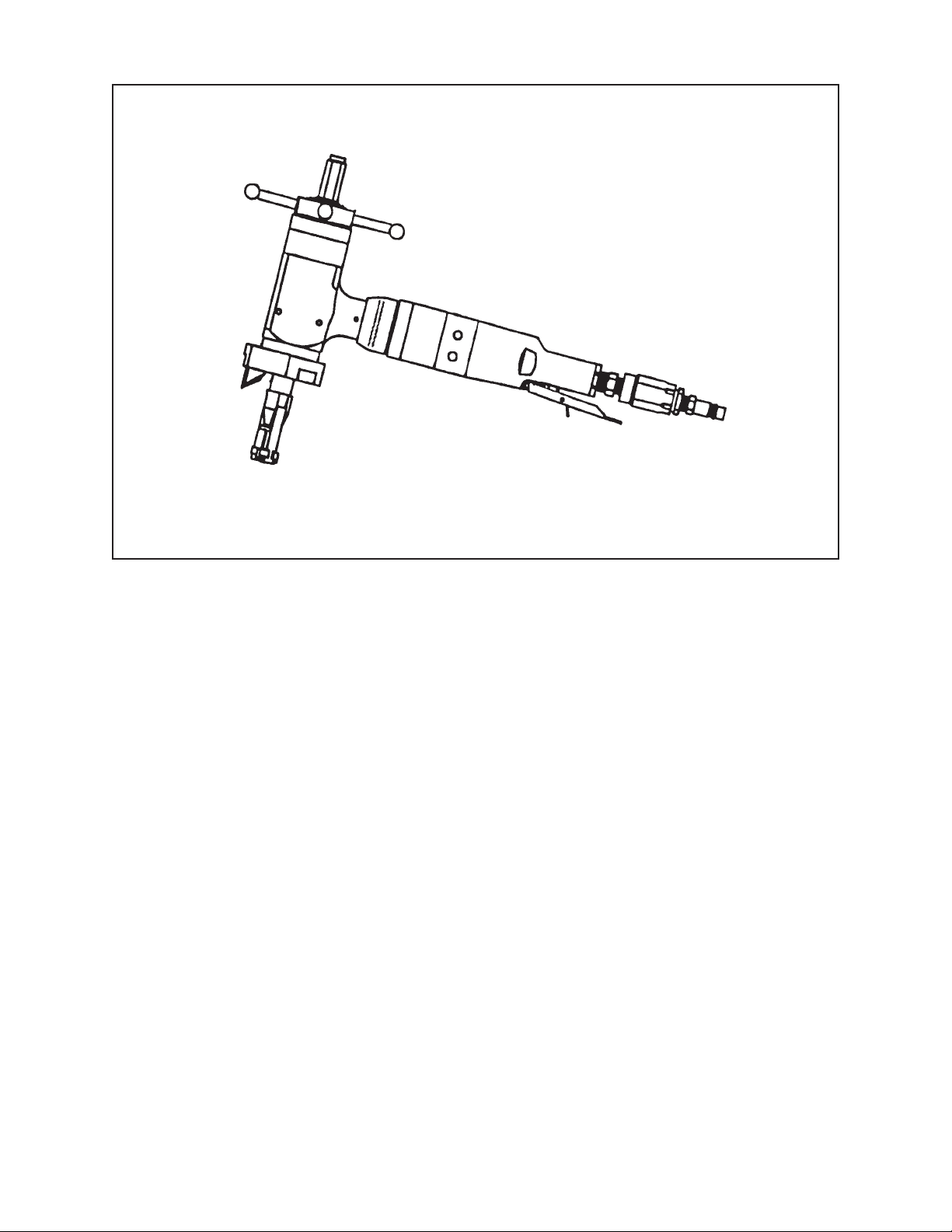
TABLE OF CONTENTS
CUSTOMER MESSAGE Inside Front Cover
SAFETY PRECAUTIONS 3
92-0699 Rev. 060412
Model 204B BEVELMASTER™
GENERAL DESCRIPTION 6
SPECIFICATIONS 7
MAINTENANCE 14
OPERATION 17
CUTTING SPEEDS AND FEEDS 22
JAW BLOCKS AND RAMP SETS 24
TOOL BITS 28
TROUBLE SHOOTING 32
ACCESSORIES 34
ILLUSTRATED PARTS BREAKDOWN 35
TOOL BIT RESHARPENING POLICY Inside Back Cover
WARRANTY INFORMATION Inside Back Cover
Page 2

Copyright 2006
Proprietary property of TRI TOOL Inc.
No reproduction, use, or duplication of the information
shown hereon is permitted without the express written
consent of TRI TOOL Inc.
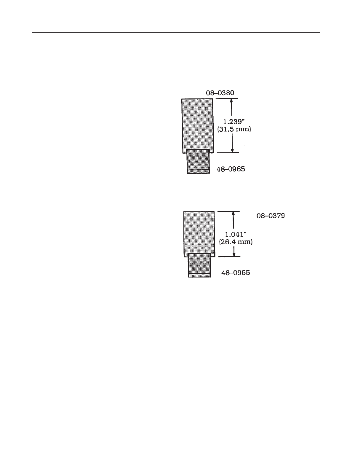
Page 3

SAFETY PRECAUTIONS
IN GENERAL
When using rotating head cutting equipment, basic safety precautions should always
be followed to reduce the risk of personal injury.
Operate this tool only in accordance with specific operating instructions.
Do not override the deadman switch on the power unit. Locking down, ob-
WARNING:
DRESS CONSIDERATIONS
structing, or in any way defeating the deadman switch on the power drive unit
may result in serious injury.
Model 204B BEVELMASTER™
Use standard safety equipment. Hard hats, safety shoes, safety harnesses, protective clothes, and other safety devices should always be used when appropriate.
Use safety glasses. Do not operate cutting tools without eye protection.
Dress properly. Do not wear loose clothing or jewelry. They can be caught in rotating and moving parts. Avoid slippery floors or wear nonskid footwear. If you have
long hair, wear protective hair covering to contain it.
WORK AREA
Keep the work area clean. Cluttered work areas and benches invite injuries.
Consider the work area environment. Keep the area well lit. Keep electrical cords,
cables, rags, rigging straps, and etc. clear of rotating equipment. Do not use powercutting tools in the presence of flammable liquids and gasses.
Keep visitors away. Do not let visitors or untrained personnel at or near operating
tools. Enforce eye protection requirements for all observers.
Do not over reach. Keep proper footing at all times.
Stay alert. Watch what you are doing. Use common sense. Do not operate tools
when you are tired.
92-0699 : Rev. 060412
3
Page 4

TRI TOOL INC.
TOOL CARE
Maintain tools with care. Keep tools in good operating condition. Sharp tool bits
perform better and safer than dull tool bits. Well maintained tools function properly
when needed.
Check for damaged parts. If a tool has malfunctioned, been dropped or hit, it must
be checked for damage. Run no-load tests and feed function checks. Do a complete visual inspection.
Electric motors. Use only with proper AC voltage power sources and observe all
normal electric shock hazard procedures.
Do not abuse power and control cords. Pulling or running over cords and cables
can result in electrical shock hazards and malfunctions. Keep control and power
cords out of all cutting fluids and water.
Hydraulic drives. Observe proper procedures for electrically driven power sources.
Avoid damage to hydraulic lines. Keep quick-disconnects clean. Grit contamination
causes malfunctions.
Air tools. Check the exhaust muffler. Broken or damaged mufflers can restrict air
flow or cause excessive noise. Use air motors only with a filtered, lubricated and
regulated air supply. Dirty air, low-pressure air or over pressure air will cause malfunctions, including delayed starting.
AREA EQUIPMENT
Secure work. Whenever possible use clamps, vises, chains and straps to secure
pipe.
Make sure the tool is secured; it is safer to have both hands free to operate the tool.
TOOL USE
Use the right tool and tool bit for the job. Do not use a tool, which is incorrect for the
job you are doing.
Keep the tool bits fully engaged in the tool bit holders. Loose bits are a safety hazard.
4
92-0699 : Rev. 060412
Page 5

Model 204B BEVELMASTER™
Disconnect power supply during setup and maintenance. Use all ‘Stop’ or Shut off’
features available when changing or adjusting tool bits, maintaining the tool, or when
the tool is not in use.
Remove adjusting keys and wrenches before applying power to the equipment.
Develop a habit of checking the tool before turning it on to make sure that all keys
and wrenches have been removed.
Do not force tools. Tools and tool bits function better and safer when used at the
feed and speed rate for which they were designed.
Do not reach into rotating equipment. Do not reach into the rotating head stock to
clear chips, to make adjustments, or to check surface finish. A machine designed to
cut steel will not stop for a hand or an arm.
Handle chips with care. Chips have very sharp edges and are hot. Do not try to pull
chips apart with are hands; they are very tough.
Avoid unintentional starts. Do not carry or handle tools with your hand on the operating switches or levers. Do not lay the tool down in a manner that will start the
drive. Do not allow the tool to flip around or move when adjusting or changing tool
bits.
Store idle tools properly. Disconnect tools from the power source and store in a safe
place. Remove tool bits for safe handling of the tool.
92-0699 : Rev. 060412
5
Page 6

TRI TOOL INC.
GENERAL DESCRIPTION
The Model 204B BEVELMASTER™ is a Pipe Beveler designed for facing, beveling
and/or counterboring the ends of pipe or tubing in preparation for welding.
These machining operations may be performed either simultaneously or separately.
Pipe weld end preparations that meet all existing conventional codes including the
more stringent nuclear codes may be machined.
The various interchangeable jaw blocks and ramps will secure the Model 204B
BEVELMASTER™ to pipe and tubing having an inside diameter ranging from 1.25”
(31.8 mm) through 4.33” (110.0 mm).
The expanding mandrel provides fast, accurate self-centering and alignment to the
pipe or tubing to be machined.
The Model 204B BEVELMASTER™ accepts the reaction torque generated by the
machining operations through the mandrel.
No additional restraining devices are required.
6
92-0699 : Rev. 060412
Page 7
Model 204B BEVELMASTER™
SPECIFICATIONS
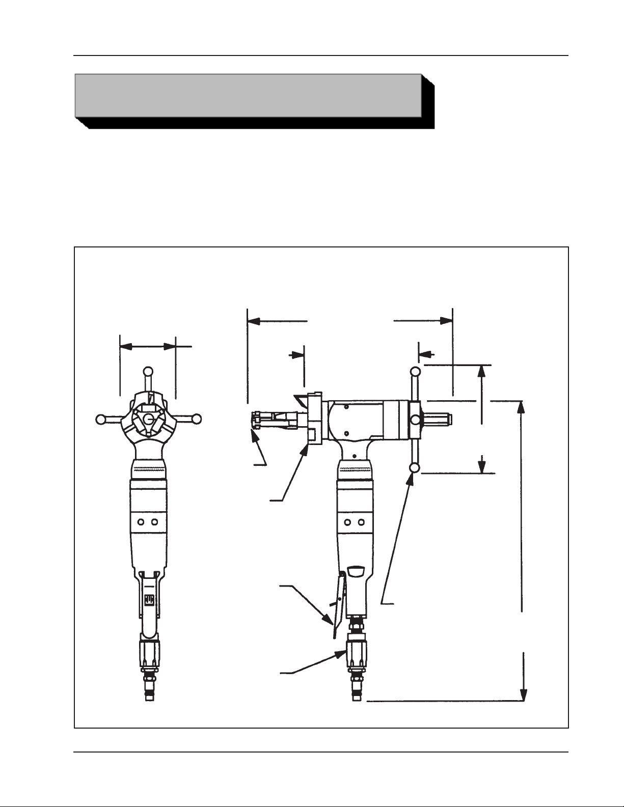
MODEL 204B BEVELMASTER™ with an AIR MOTOR
Weight 18 lbs (8.1 kg)
Power Requirements 55 cfm at 90 psi (26 L/s at 621 kPn)
Envelope Drawing
16.42"
(417.1 mm)
4.00"
(101.6 mm)
Mandrel
Cutting Head
(Travel 1.5"
maximum)
Safety Lever
8.97"
(227.8 mm)
7.18"
(182.4 mm)
On/Off
Inline Feed
19.88"
(505.0 mm)
Control Valve
92-0699 : Rev. 060412
Air Flow
(Speed)
7
Page 8

TRI TOOL INC.
PIPE CUTTING CAPACITIES
Basic Pipe Sizes
All schedules of 1 1/4” through 4” pipe.
Some schedules may require optional equipment.
Basic Tube Size
Up to .531” ( 13.5mm ) wall tubing with a maximum O.D. of 4.50” ( 114.3mm )
and a minimum I.D. of 1.25” ( 31.7mm ) may be beveled with standard
mandrel.
Wall Thickness Capacity
Wall thickness of all standard pipe schedules [.531” (13.5mm) maximum] in
the range listed. Contact Tri Tool for heavier wall procedures.
Counterboring Operations
The tool will counterbore pipe and tubing with an I.D. range of 1.50” (38.1mm)
to 4.33” ( 110.2mm ).
Material Cutting Capabilities
Mild steels, Chrome steels ( Rc 35 max ), stainless steel, copper-nickel alloys
and aluminum without limitations except size and wall thickness as specified
in paragraph #2.
Inconel and some other high temperature alloys may require special procedures as a function of wall thickness and type of end preparation. Contact
Tri Tool’s Engineering Department for details.
CLEARANCE AND DIMENSIONS
Rotating Head DIA. 4.00” ( 101.6mm )
Length Over Motor 19.88” ( 505.0mm )
Length (of machine ) 8.97” ( 227.8mm )
Available Feed Travel 1.50” ( 38.1mm )
8
92-0699 : Rev. 060412
Page 9

DRIVE SYSTEM
Final Drive Gear Driven
Pneumatic Motor
Free speed 325 rpm
Max. H.P. speed 162 rpm
POWER SUPPLY
Pneumatic motor requires 55 cfm ( 26 L/s ) air supply at 90 psi ( 621 kPa ) for
maximum horsepower delivery.
Note: Air Supply must have a filter/regulator/lubricator ( FRL ) system to protect the
warranty on the air motor.
Model 204B BEVELMASTER™
CUTTING HEAD SPEEDS
Maximum Cutting Head Speed 162 rpm
Cutting Head Speed @ Maximum H.P. 82 rpm
Functional Speed Range 20-100 rpm
RPM at 300 Surface Inches Per Minute
4.50” ( 114.3mm ) 21 rpm
1.25” ( 31.8mm ) 76 rpm
SPEED CONTROL
On/off safety lever valve and twist-type air flow control valve.
MOUNTING
Manually actuated draw rod expands mandrel ramps and jaw blocks.
FEED
Manual-Feed Handle is in line at the back of the machine. Feed rate is
.100” (2.5mm ) per revolution of the feed handle.
92-0699 : Rev. 060412
9
Page 10
TRI TOOL INC.
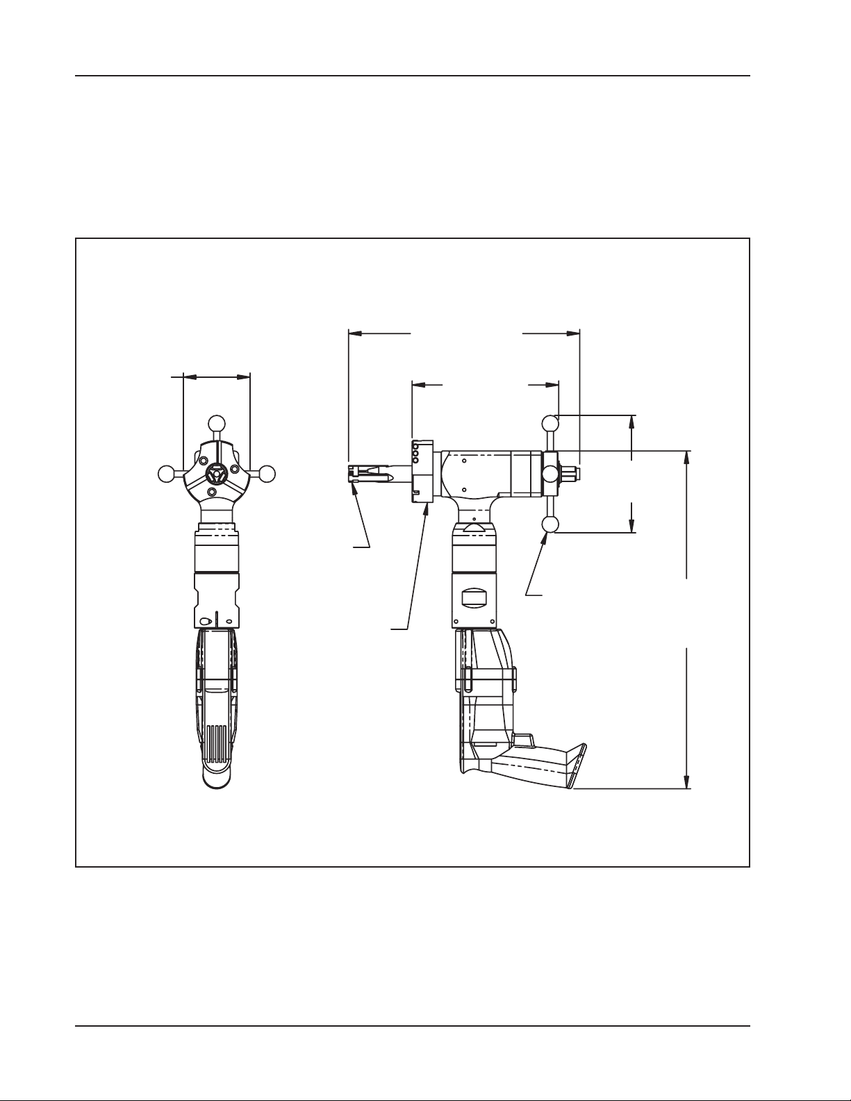
MODEL 204B BEVELMASTER™ with an ELECTRIC MOTOR
Weight 18 lbs (8.1 kg)
Power Requirements 115 VAC, 28 to 60 Hz 5.25 amp
Envelope Drawing
16.57"
(420.88 mm)
4.00"
(101.60 mm)
Mandrel
Cutting Head
(Travel 1.5"
maximum)
8.79"
(223.27 mm)
7.03"
(178.56 mm)
In-line Feed
20.25"
(514.35 mm)
10
92-0699 : Rev. 060412
Page 11

PIPE CUTTING CAPACITIES
Basic Pipe Sizes
1” Pipe
Schedule 40 (Small Mandrel required to mount in 1” schedule 80 and
above.)
1 1/4” through 2 1/2” Pipe
Up to Schedule 80
3” through 4” Pipe
Up to Schedule 40
* Some Schedules may require optional equipment.
Model 204B BEVELMASTER™
Basic Tube Sizes
Up to .250” (6.4 mm) wall tubing with a maximum OD of 4.50” (114.3 mm)
and a minimum ID of 1.25” (31.7 mm) may be beveled with standard mandrel.
Wall Thickness Capacity (Limitations)
Wall thickness of schedules listed, .276” (7 mm) maximum, in the range listed
can be machined without limitations.
Wall thicknesses greater than .276” (7 mm) require special procedures and
are subject to Duty Cycle limitations to prevent motor damage. Contact Tri
Tool Inc. for heavier wall procedures.
Counterboring Operations
The tool will counterbore pipe and tubing with an ID of 1.50” (38.1 mm) to
4.33” (110.2 mm).
DUTY CYCLE
The 204BE with an electric motor (P/N 58-0147 or equivalent) duty cycle on high
cutting load applications (see above), is limited to 50% ‘On’ time with a maximum of
five (5) minutes continuos ‘On’ time.
92-0699 : Rev. 060412
11
Page 12

TRI TOOL INC.
MATERIAL CUTTING CAPABILITIES
Mild steels, chrome steels, (Rc 35 max), stainless steel, copper-nickel alloys and
aluminum without limitations except size and wall thickness as specified in the
above paragraphs.
Inconel and some other high temperature alloys may require special procedures as
a function of wall thickness and type of end preparations. Contact Tri Tool’s
Engineering Department for details.
CLEARANCE AND DIMENSIONS
Rotating Head DIA. 4.00” (101.6 mm)
Length 8.97” (227.8 mm)
Length Over Motor 20.25” (514.35 mm)
Available Feed Travel 1.50” (38.1 mm)
DRIVE SYSTEM
Final Drive Gear Driven
Electric Motor - 2 speed Ranges & 6:1 Gear Reduction
Free speed
Max. HP Speed
Low Range 112 rpm
High range 210 rpm
Low Range 168 rpm
High Range 316 rpm
POWER SUPPLY
115 VAC, 5.25 Amps, 28 to 60 Hz.
12
92-0699 : Rev. 060412
Page 13

CUTTING HEAD SPEEDS
Max. Cutting Head Speed
Low Range 84 rpm
High Range 156 rpm
Cutting Head Speed @ Max. H.P.
Low Range 56 rpm
High Range 105 rpm
Functional Speed Range 20 to 100 rpm
Speed Control
Model 204B BEVELMASTER™
MOUNTING
Manually actuated draw rod expands mandrel ramps and jaw blocks.
FEED
Manual-Feed Handle is in line at the back of the machine. Feed rate is .100”
(2.5mm) per revolution of the feed handle.
On/Off Trigger control with Variable Speed.
92-0699 : Rev. 060412
13
Page 14
TRI TOOL INC.
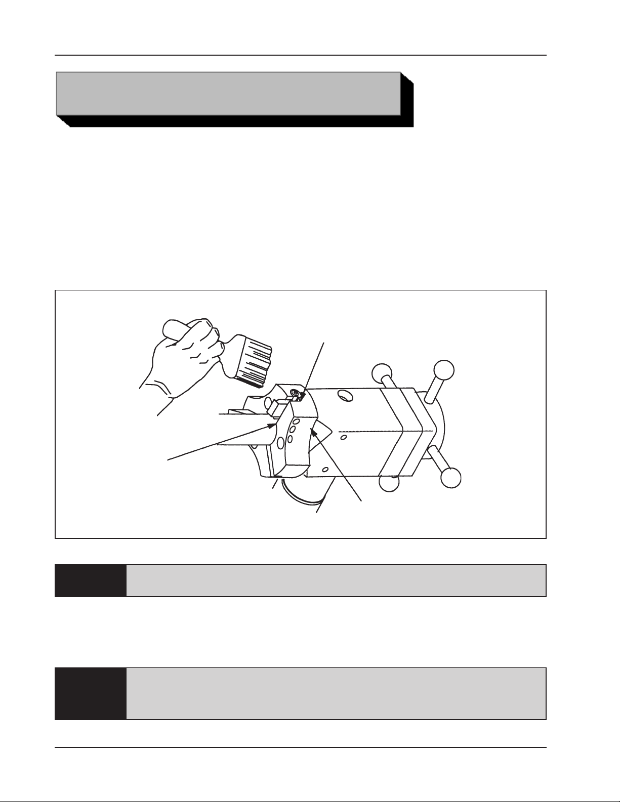
All components should be cleaned and coated with a light film of oil prior to use.
Use a clean, non-detergent oil, preferably SAE 10 (90 SSU) or lighter or oil as
specified for the air motor.
Air supply for the Model 204B BEVELMASTER™ with an Air Motor requires an
adequate filter/regulator/lubricator (FRL) to be used.
A maximum of 90 psi (621 kPa) line pressure is recommended.
MAINTENANCE
Clean Up
Clean Up
Clean Up
NOTE:
When the Model 204B BEVELMASTER™ is operated in the vertical position, cutting
head up, it should be turned upside down and the chips and/or other debris removed
after each bevel has been completed.
NOTE:
The motor warranty is void if damage occurs from contaminated air or lack of
lubrication.
Tool life may be severely shortened, unless chips and/or other debris that
have been deposited on the cutting head during the machining operations are
removed.
14
92-0699 : Rev. 060412
Page 15
Model 204B BEVELMASTER™
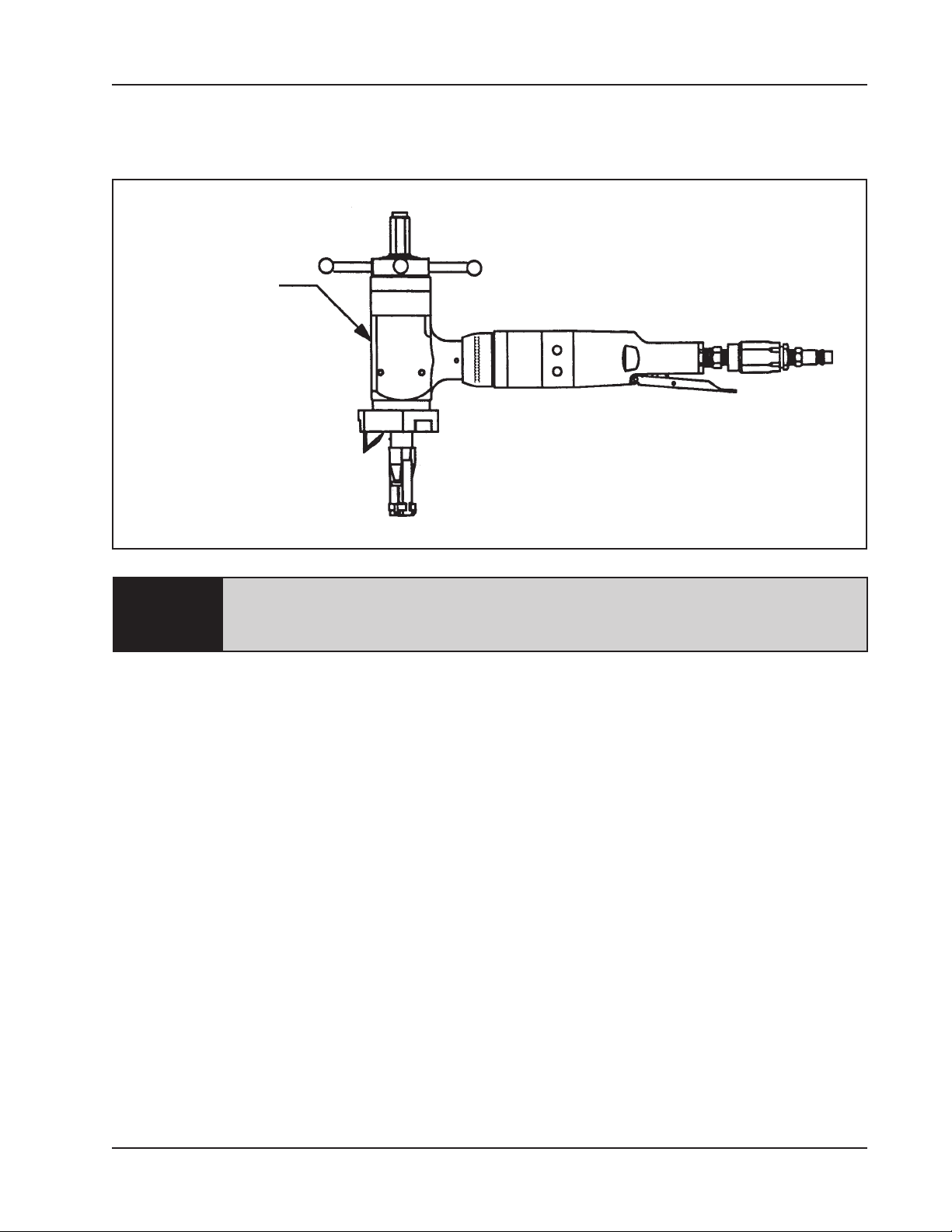
Verify that there is adequate grease in the gear box. Gears and bearings are to be
lubricated using a lithium based grease.
Grease Port
Disassembly of a power unit voids warranty, except when performed by a
NOTE:
AIR MOTOR LUBRICATION
No direct maintenance is normally required on the air motor.
The FRL unit must be maintained as required, frequency dependent on the basic air
supply, to keep the water trap drained, filter cleaned and the lubricator oil reservoir
filled so that a drop of oil every two (2) to five (5) seconds is flowing.
TRI TOOL INC. designated repair technician. A letter of designation is
required.
However, the air supply must flow through a filter/regulator/lubricator (FRL)
unit or separate units before arriving at the air motor.
If the Model 204B BEVELMASTER™ is to be left idle for 24 hours or more
after being run on ‘wet’ air, it is advisable to squirt oil directly into the air motor
inlet and run the motor for two (2) to three (3) seconds.
This will prevent rusting and ‘freezing‘ of the rotor vanes.
92-0699 : Rev. 060412
15
Page 16

TRI TOOL INC.
Lubricant Recommendations
The air motor requires a Class 2 lubricant, viscosity of 100 to 200 SSU at
100
TRI TOOL Inc. – Air Tool Lubricant (P/N 68-0022)
The bearings in the Air and Electric Motor are sealed and do not require any
lubrication.
The drive gears require a lithium based grease.
°
F (38° C) minimum aniline point of 200° F (93° C).
• AMOCO – American Industrial Oil No. 32
• Atlantic Richfield – Duro Oil S 150
• Chevron – A. W. Machine Oil 32
• Exxon – Nuto H32
• Shell – Tellus Oil 32
16
92-0699 : Rev. 060412
Page 17
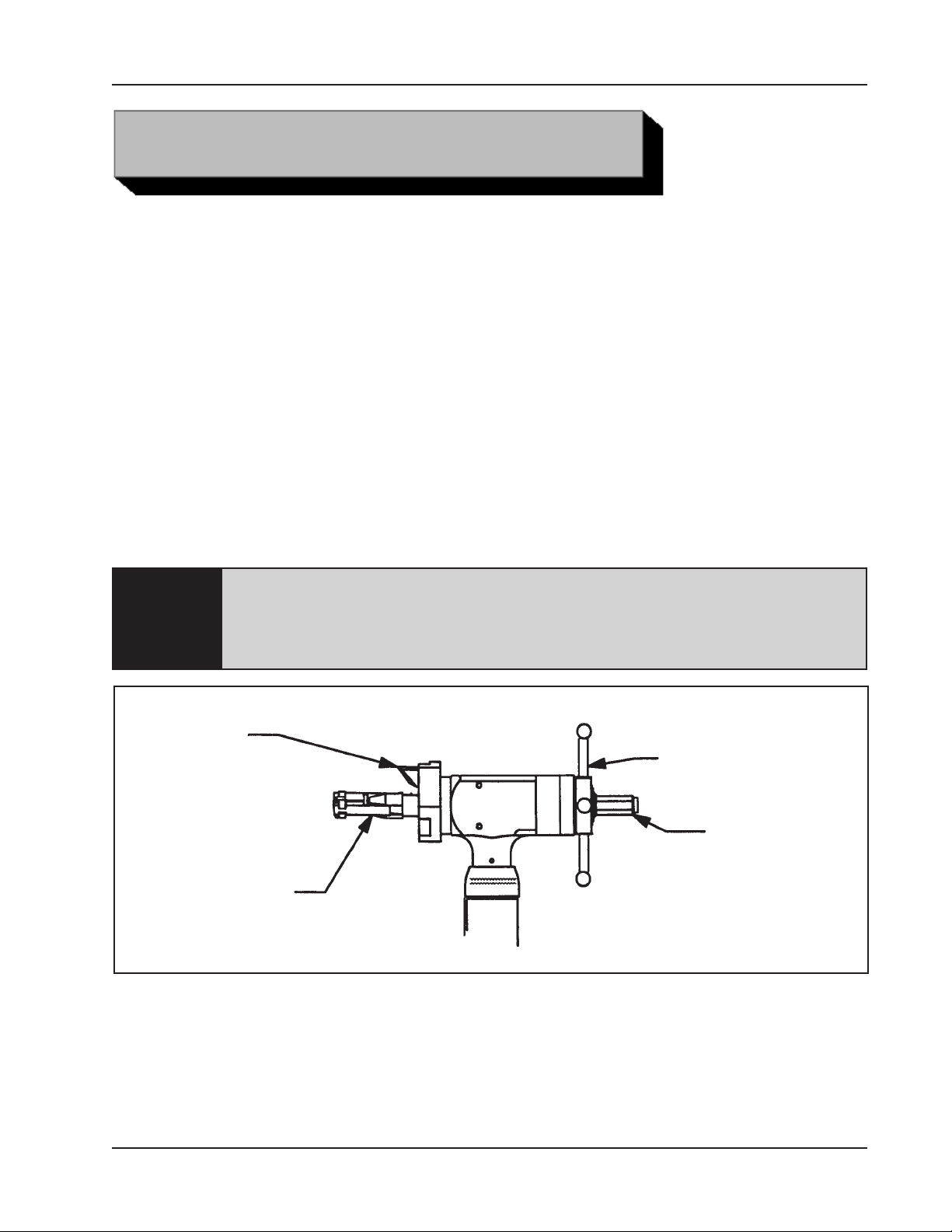
Read the operating instructions carefully before attempting to operate the Model
204B BEVELMASTER™
Use eye protection at all times when operating the Model 204B BEVELMASTER™
INSTALLATION
Select the recommended jaw blocks for the pipe size to be machined.
Gently slide the mandrel assembly into the Model 204B BEVELMASTER™ until it
comes to a stop against the torque acceptance key.
Rotate the mandrel assembly as required to engage the torque acceptance key of
the Model 204B BEVELMASTER™ with the slot in the mandrel shaft.
Model 204B BEVELMASTER™
OPERATION
Since the mandrel shaft will contact the torque acceptance key before the
NOTE:
Rotate the feed handle clockwise to engage the feed nut with the thread on the
mandrel shaft.
feed nut engages the mandrel shaft threads, caution should be taken not to
force, or allow, the machine to impact the lead threads of the feed nut with the
lead threads of the mandrel.
Tool Bit
Feed
Handle
Draw Nut
Mandrel
Assembly
The Model 204B BEVELMASTER™ with the mandrel assembly installed maybe
mounted into the pipe or tube as one unit.
92-0699 : Rev. 060412
17
Page 18
TRI TOOL INC.
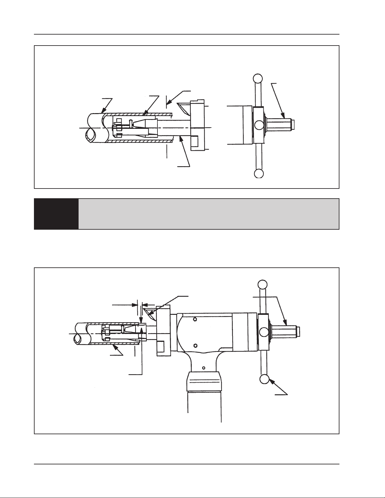
Pipe
Jaw Block
and/or
Ramp
Mandrel Assembly
Final Prep
Location
Draw Nut
In order to avoid cutting the ramps and/or jaw blocks during the machining
NOTE:
operation, the mandrel must be installed beyond the final preparation
location.
Tighten the draw nut to force the jaw blocks out to the inside diameter of the pipe or
tube.
18
1/8" (3 mm)
Clearance
Pipe
Mandrel
Clearance
Tool Bit
Draw Nut
Feed Handle
92-0699 : Rev. 060412
Page 19
Verify a clearance of 1/8” (3 mm) minimum between the tool bit and the pipe face.
Select the tool bit(s) required to machine the pipe to the configuration desired.
WARNING:
Model 204B BEVELMASTER™
Use of dull or improperly designed tool bits or tool bits not manufactured by
TRI TOOL INC. may result in poor performance and may constitute abuse of
the machine and therefore voids the TRI TOOL INC. factory warranty.
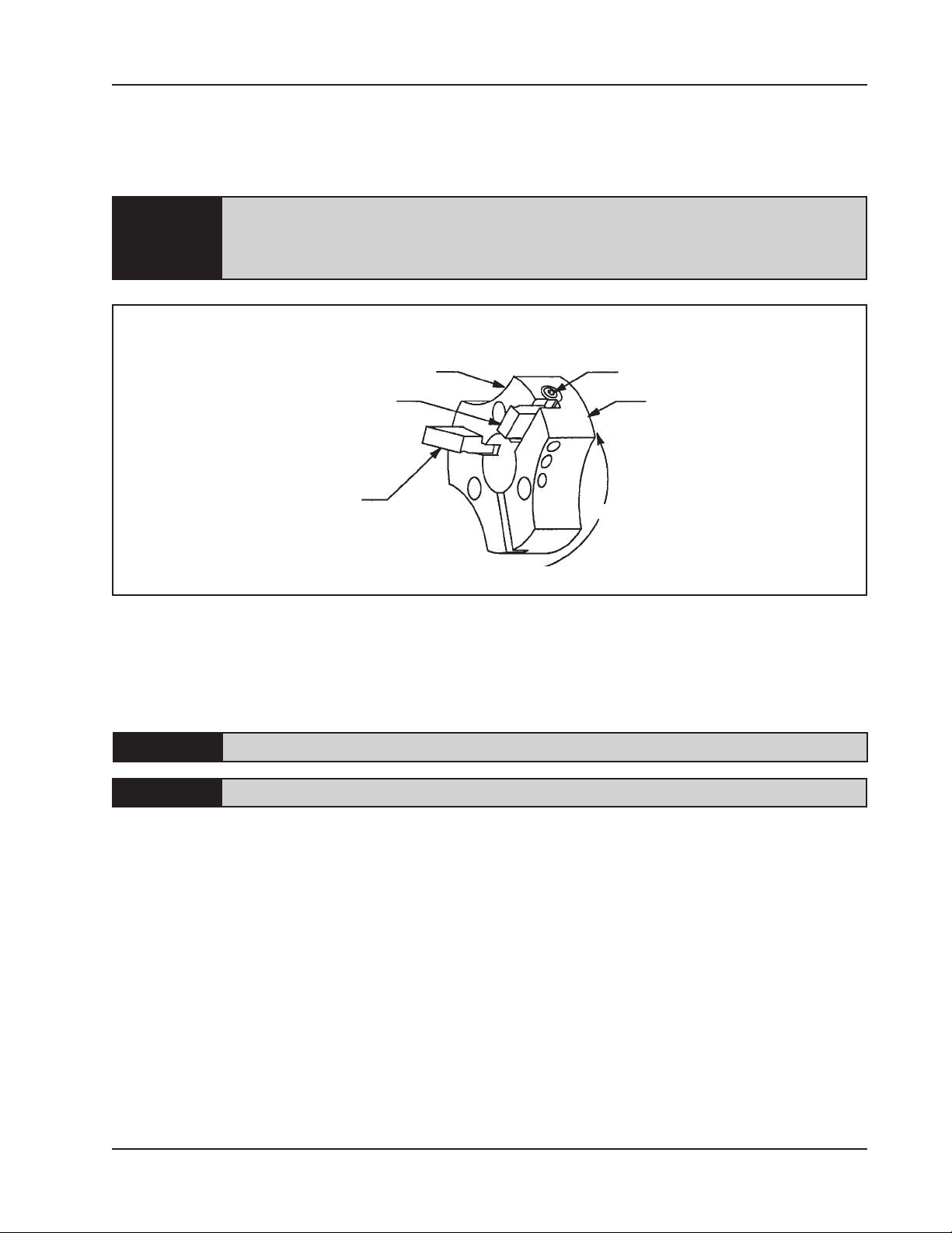
Cam Adjustment
Lock (On the Side)
Cam Adjustment
Cutting Edge, Tool Bit,
Facing (Land)
Cutting Edge,
Tool Bit, Beveling
When performing any multiple machining operation such as facing and beveling, the
facing tool bit should be installed as shown.
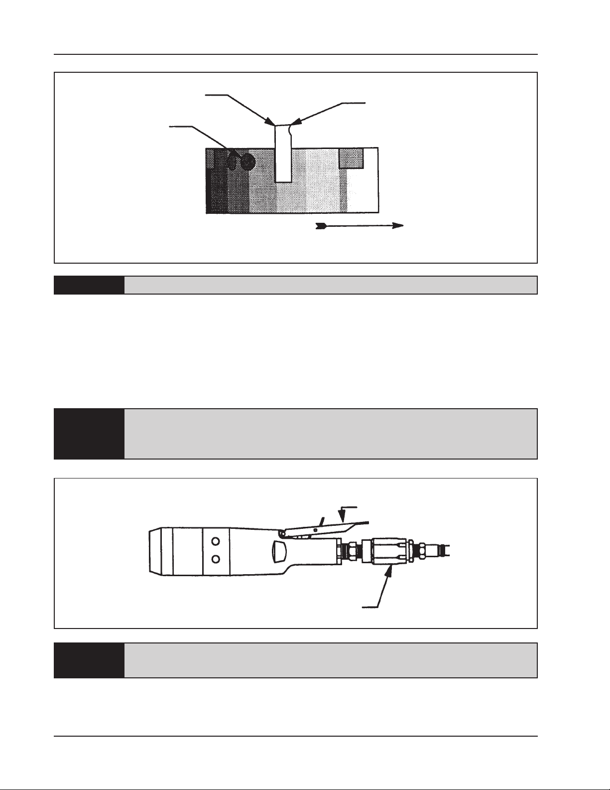
Insert the tool bit(s) into the slot(s) in the cutting head.
CAUTION:
CAUTION:
Make sure that there is a clearance between the tool bit(s) and the mandrel.
The cutting edge of the tool bit(s) must be located on the radial centerline.
Insure that no tool bit is installed backwards.
Rotation
Cutting Head
Tighten the setscrews to secure the tool bit in the tool bit slot.
Adjust the bevel tool bit radially to control the land width.
Adjust the cam to alter the width of the land with the facing tool bit.
Attach the proper air supply line to the Model 204B BEVELMASTER™
92-0699 : Rev. 060412
19
Page 20
TRI TOOL INC.
Tool Bit
Set Screws
NOTE:
Check that the filter/regulator/lubricator (FRL) is installed and set properly.
MACHINING SEQUENCE
Depress the air motor trigger. Adjust the cutting speed by rotating the flow valve at
the air connection.
Cutting Edge
Rotation
Rotate the feed handle clockwise to bring the tool bit(s) and pipe closer together.
WARNING:
CAUTION:
DO NOT OVERRIDE THE DEADMAN SWITCH ON THIS UNIT. Locking
down, obstructing, or in any way defeating the deadman switch on this unit
may result in serious injury.
Deadman Switch
Flow Control Valve
The actual machining operation will begin when the first tool bit contacts the
pipe.
20
When the pipe end is not square to the pipe axis, the Tool Bit will contact only a
small segment of the pipe during each revolution.
92-0699 : Rev. 060412
Page 21

Model 204B BEVELMASTER™
To avoid tool bit damage, the feed rate should be very slow until the tool bit(s) is in
contact with the pipe continually during at least one full revolution.
Continue rotating the feed handle clockwise until the end of the pipe is completely
machined.
Discontinue feed and allow the head to rotate one (1) to three (3) revolutions to
improve finish of the prep surface.
Release the air motor trigger to stop the head rotation.
Rotate the feed handle counterclockwise to separate the tool bit(s) from the pipe.
Rotate the feed handle counterclockwise until the tool bit to pipe relationship is the
same as described.
Loosen the draw nut on the mandrel to release the mandrel from the pipe.
The mandrel assembly may be left in the Model 204B BEVELMASTER™ and
installed as a complete assembly.
92-0699 : Rev. 060412
21
Page 22
TRI TOOL INC.
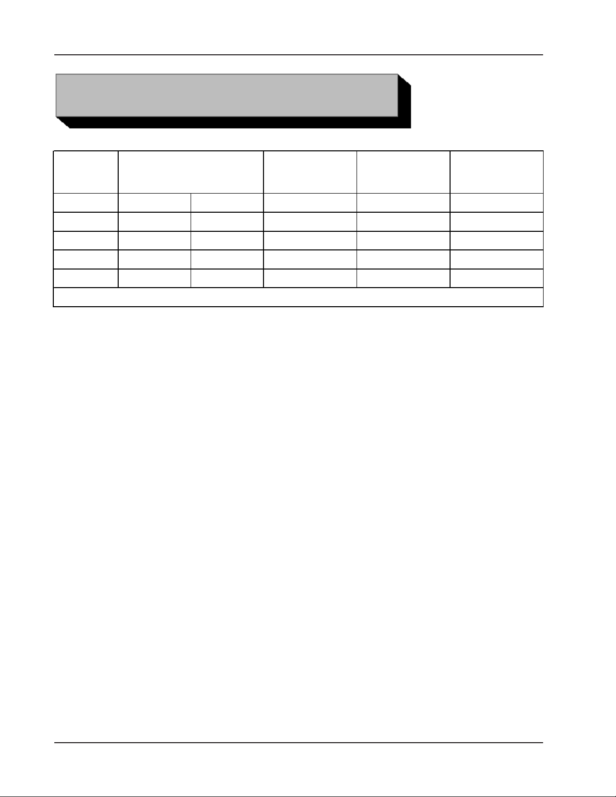
CUTTING SPEEDS AND FEEDS
RPM for
Pipe Size True DIA
1" 1.315" 33.4 mm 48 61 73
2" 2.375" 60.3 mm 27 34 40
3" 3.500" 88.9 mm 18 23 27
3 1/2" 4.000" 101.6 mm 16 20 24
4" 4.500" 114.3 mm 14 18 21
Cutting Speed (Approximately)
200 in/min
(5080 mm/min)
RPM for
250 in/min
(6350 mm/min)
Use 200 surface inches per minute (5080 surface millimeters per minute) for:
Stainless steels in general when no coolant is allowed, all heavy-wall tube
and some chrome/molybdenum steels.
Use 250 surface inches per minute (6350 surface millimeters per minute) for:
Mild steels and some thin-wall stainless steels when coolants are permitted
and applied.
RPM for
300 in/min
(7620 mm/min)
Use 300 surface inches per minute (7620 surface millimeters per minute) for:
Aluminum and some thin-wall mild steel and tube with coolants.
BASIC FEED RECOMMENDATION
Use very light feed for initial beveling or until a continuous cut is established.
This is very important for longer tool bit life when cutting through flame cut or out of
square pipe ends.
Use adequate feed, .003” to .006” (.08 mm to .15 mm) per revolution thereafter, to
establish a continuous chip cut.
If the feed is too light, only light stringer chips will be removed.
22
92-0699 : Rev. 060412
Page 23

Model 204B BEVELMASTER™
If the feed is too heavy the drive will start to overload and the chip will start to
have a rough or torn appearance.
Stainless steel, which work hardens, must be worked with a heavy enough feed to
stay under the work hardened surface .003" (.08 mm) to .006" (.15 mm).
Never allow the Tool Bit to burnish the surface.
Reduced feeds and speeds will normally minimize chatter problems.
92-0699 : Rev. 060412
23
Page 24
TRI TOOL INC.
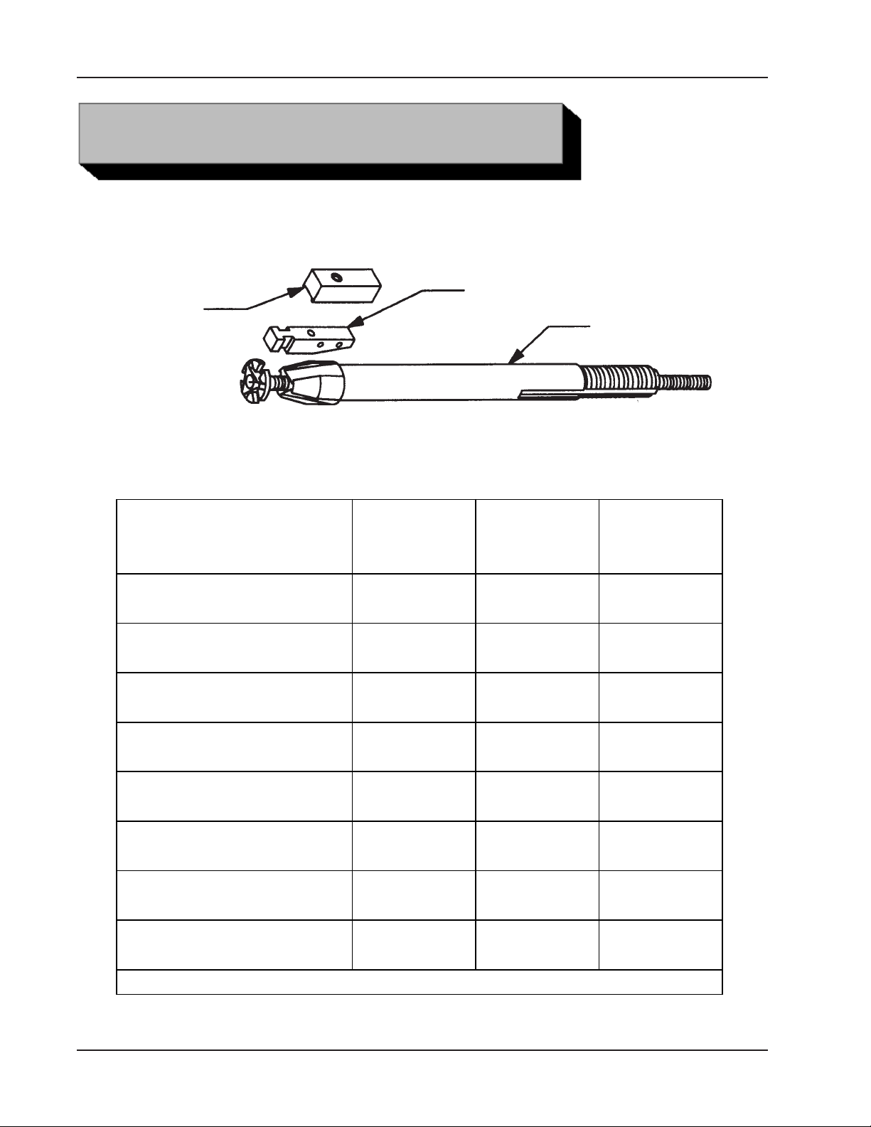
JA W BLOCKS AND RAMP SETS
Block
STEEL JAW BLOCKS AND RAMPS
Ramp
Mandrel Assembly
Used with Mandrel Assembly (P/N 06-0419)
ID
Mounting
Range
1.250" to 1.630"
(31.8 mm to 41.4 mm)
1.560" to 2.000"
(39.6 mm to 50.8 mm
1.930" to 2.390"
(49.0 mm to 60.7 mm)
2.320" to 2.780"
(58.9 mm to 70.6 mm)
2.710" to 3.160"
(68.8 mm to 80.3 mm)
3.090" to 3.550"
(78.5 mm to 90.2 mm)
3.480" to 3.940"
(88.4 mm t o 100.1 mm)
Standard
Ramp
(3 Req 'd)
48-0965
48-0966 N/A
48-0965
48-0965
48-0965
48-0965
Jaw Block
Assembly
( 3 Req'd)
N/A
N/A
08-0376
08-0377
08-0378
08-0379
Block
Height
N/A48-0964
N/A
N/A
.442"
(11.2 mm)
.645"
(16.4 mm)
.841"
(21.4 mm)
1.041"
(26.4 mm)
3.870" to 4.330"
(98.3 mm t o 110.0 mm)
NOTE: Blocks can only be mounted on the #2 Ramp (P/N 48- 0965)
48-0965
08-0380
24
1.239"
(31.5 mm)
92-0699 : Rev. 060412
Page 25
Model 204B BEVELMASTER™
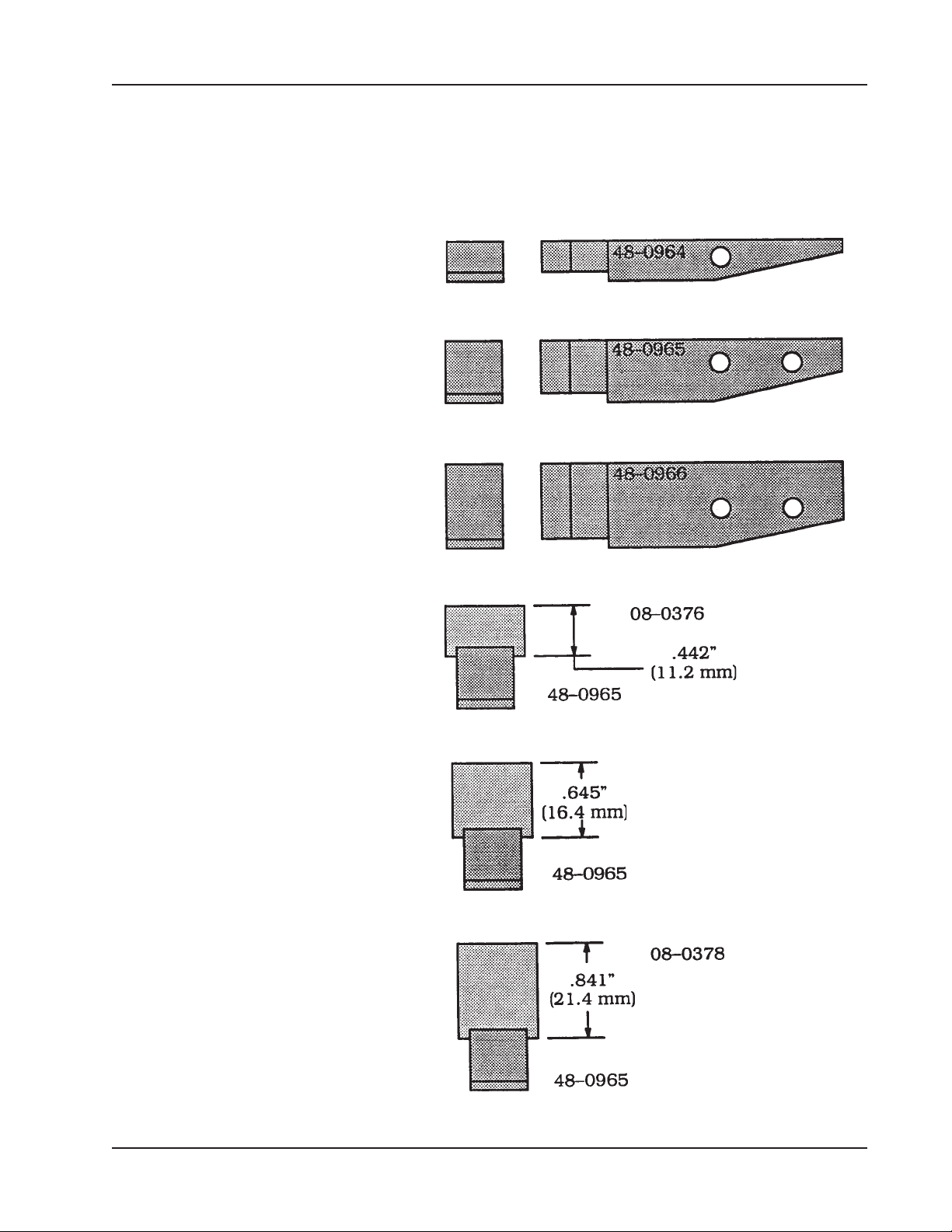
STEEL JAW BLOCK AND RAMP PROFILES - STANDARD MANDREL
Mounting ID Ramp and Block Combination
1.250" to 1.630"
(31.8 mm to 41.4 mm)
1.560" to 2.000"
(39.6 mm to 50.8 mm)
1.930" to 2.390"
(49.0 mm to 60.7 mm)
2.320" to 2.780"
(58.9 mm to 70.6 mm)
2.710" to 3.160"
(68.8 mm to 80.3 mm)
3.090" to 3.550"
(78.5 mm to 90.2 mm)
92-0699 : Rev. 060412
25
Page 26
TRI TOOL INC.
STEEL JAW BLOCK AND RAMP PROFILES - STANDARD MANDREL
Mounting ID Ramp and Block Combination
3.480" to 3.940"
(88.4 mm to 100.1 mm)
3.870" to 4.330"
(98.3 mm to 110.0 mm)
26
92-0699 : Rev. 060412
Page 27
Model 204B BEVELMASTER™
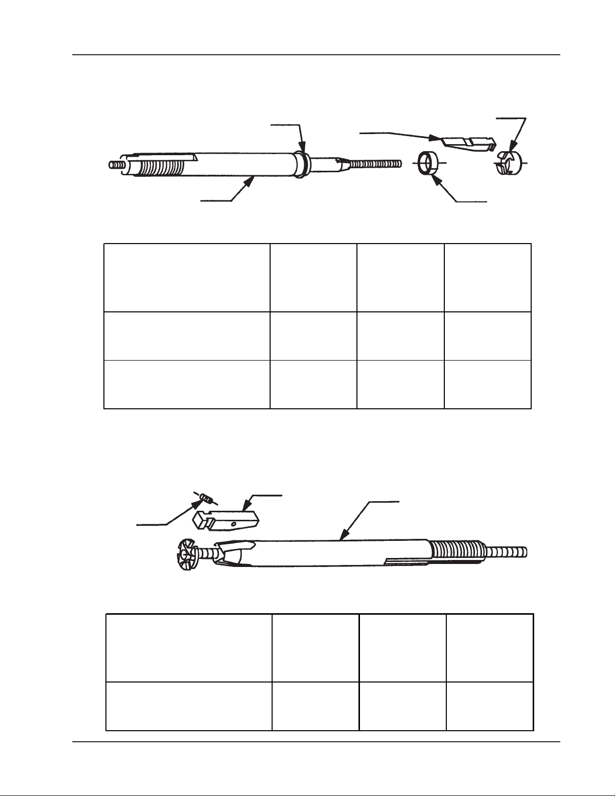
BUTT PLATE, SPRING AND RAMPS
Mandrel Sleeve
Mandrel Assembly
Used with Mandrel Assembly (P/N 06-0413)
ID
Mounting
Range
.610" to .800"
(15.5 mm to 20.3 mm)
.800" to 1.000"
(20.3 mm to 25.4 mm)
Butt Plate
Ramp
Spring
Butt
Spring
Ramp
Plate
P/N
P/N
P/N
24-1463 40-0130 48-0596
24-1464 40-0136 48-0597
Spring
ID
Mounting
Range
1.000" to 1.250"
(25.4 mm to 31.8 mm)
BUTT PLATE, SPRING AND RAMP
Ramp
Mandrel Assembly
Used with Mandrel Assembly (P/N 06-0414)
Butt
Spring
Plate
P/N
P/N
24-1462 40-0108 48-0976
Ramp
P/N
92-0699 : Rev. 060412
27
Page 28
TRI TOOL INC.
Pipe
TOOL BITS
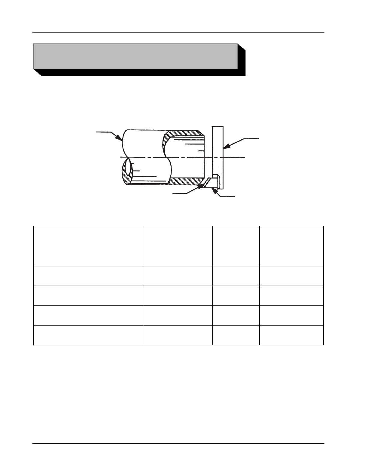
TOOL BIT, 37.5° BEVELING
Cutting Head
Range
1 1/4" ID thru 3" pipe
(31.8 mm ID thru 88.9 mm OD )
1 1/4" ID thru 3" pipe
(31.8 mm ID thru 88.9 mm OD )
3" thru 4" pipe
(2.11 mm ID thru 114.3 mm OD)
3" thru 4" pipe
(2.11 mm ID thru 114.3 mm OD)
Cutting Edge
Thickness
.531" (13.5 mm) 99-0333
.531" (13.5 mm) 99-3111
.531" (13.5 mm) 99-3711
.531" (13.5 mm) 99-3712
Max.
Wall
Tool But, Beveling
Pipe
or
Tube
Mat'l
CS
SS
CS
SS
37.5°
Beveling
Tool Bit
P/N
28
92-0699 : Rev. 060412
Page 29
Pipe
Model 204B BEVELMASTER™
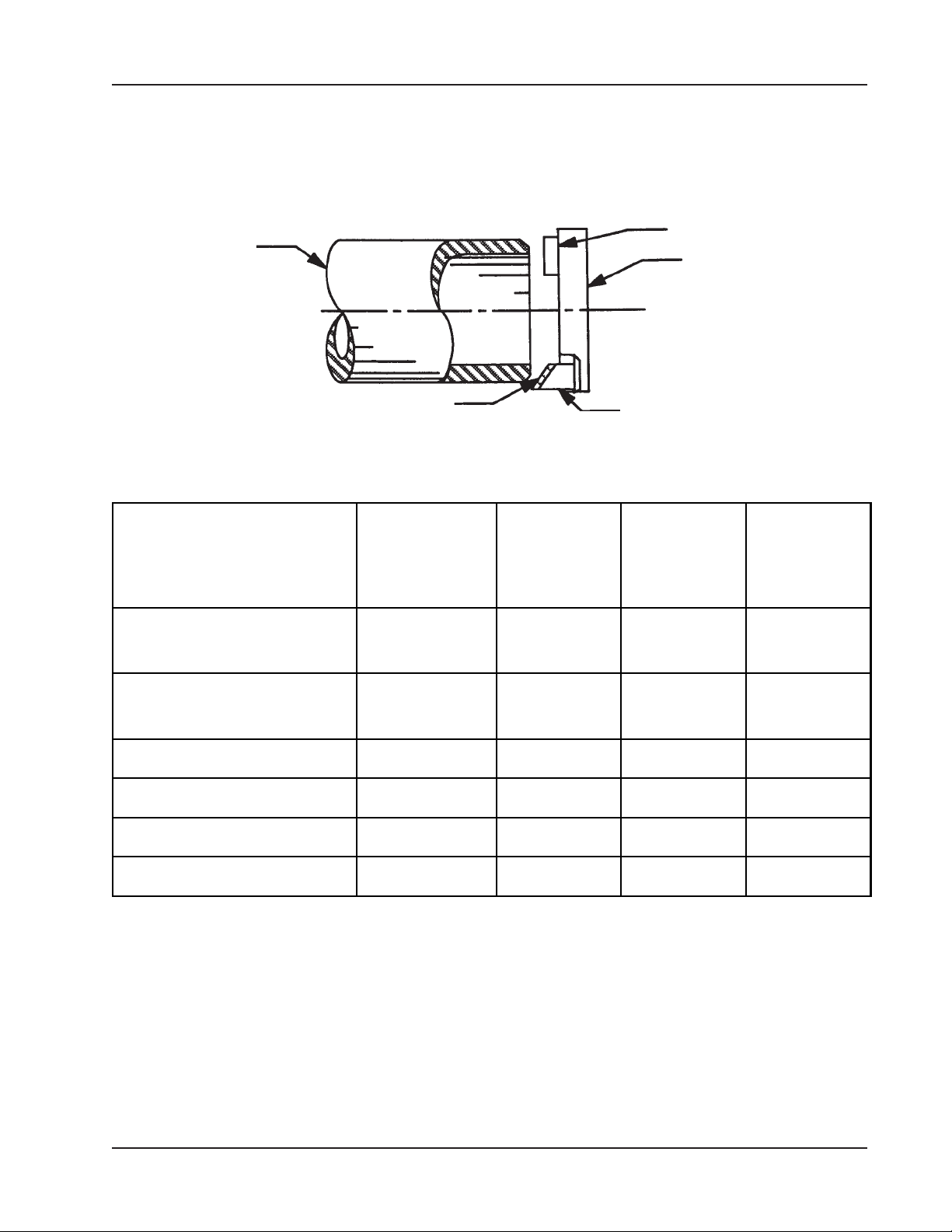
TOOL BIT, BEVELING AND FACING
Facing Tool Bit
Cutting Head
Cutting Edge
Max.
Range
1 1/4" pipe - sch 10 thru 40
up to
2 1/2" pipe - all schs
1 1/4" pipe - sch 10 thru 40
up to
2 1/2" pipe - all schs
3" and 3 1/2" pipe - all schs .531" (13.5 mm) CS 99-3711 99-3571
3" and 3 1/2" pipe - all schs .531" (13.5 mm) SS 99-3712 99-0714
4" pipe - sch 40 thru 160 .531" (13.5 mm) CS 99-3711 99-3571
Wall
Thickness
.531" (13.5 mm) CS 99-0333 99-0257
.531" (13.5 mm) SS 99-3111 99-0789
Pipe
or
Tube
Mat'l
Tool Bit, Beveling
37.5°
Beveling
Tool Bit
P/N
Facing
Tool Bit
P/N
4" pipe - sch 40 thru 160 .531" (13.5 mm) SS 99-3712 99-0714
92-0699 : Rev. 060412
29
Page 30
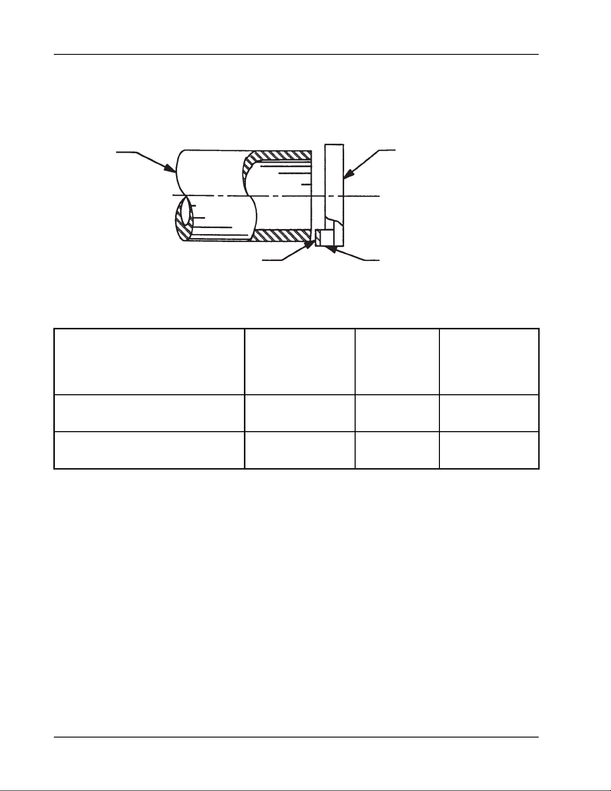
TRI TOOL INC.
TOOL BIT, FACING (LAND)
Pipe
Cutting Edge
Range
1 1/4" ID thru 4" pipe
(31.8 mm ID thru 114.3 mm OD)
Cutting Head
Tool Bit, Facing (Land)
Max.
Wall
Thickness
.531" (13.5 mm) 99-0485
Pipe or
Tube
Mat'l
CS
Facing
Tool Bit
P/N
1 1/4" ID thru 4" pipe
(31.8 mm ID thru 114.3 mm OD)
.531" (13.5 mm) 99-0277
SS
30
92-0699 : Rev. 060412
Page 31
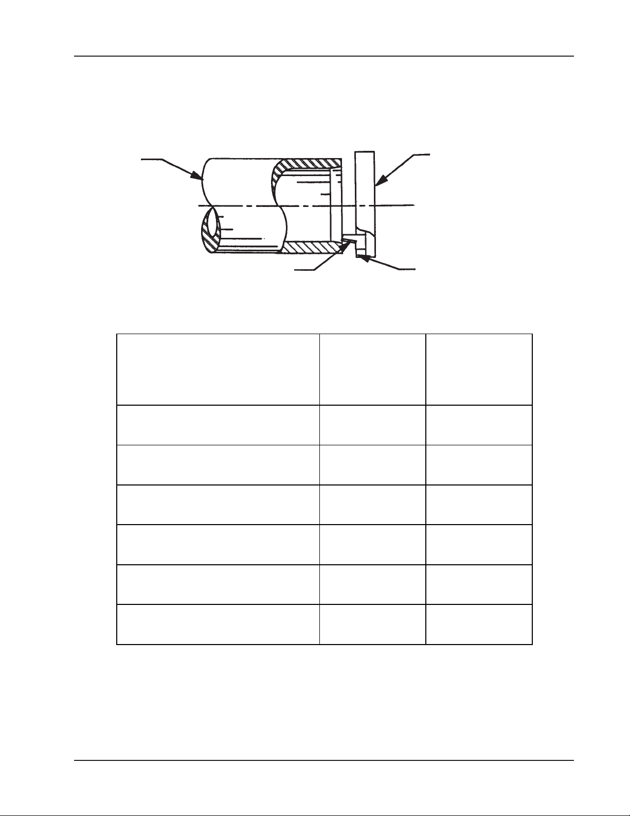
Model 204B BEVELMASTER™
TOOL BIT, ID CHAMFER
Pipe
Cutting Edge Tool Bit, ID Chamfer
Range
1.60" ID thru 2.66" ID
(40.6 mm thru 67.6 mm)
Pipe
or Tube
Material
CS
Cutting Head
ID Chamfer
Tool Bit
P/N
99-0168
1.60" ID thru 2.66" ID
(40.6 mm thru 67.6 mm)
2.14" ID thru 3.32" ID
(54.4 mm thru 84.3 mm)
2.14" ID thru 3.32" ID
(54.4 mm thru 84.3 mm)
2.90" ID thru 4.19" ID
(73.7 mm thru 106.4 mm)
2.90" ID thru 4.19" ID
(73.7 mm thru 106.4 mm)
SS
CS
SS
CS
SS
99-3713
99-0833
99-3714
99-0320
99-0288
92-0699 : Rev. 060412
31
Page 32

TRI TOOL INC.
TROUBLE SHOOTING
Problem: The Tool Bit Chatters
The tool bit is loose or overextended.
The tool bit is damaged.
The tool holder is too loose in the slides.
The cutting speed is too fast.
The clamping pads are loose on the pipe or tube.
Cutting fluid is required.
The main bearing pre-load is loose.
Problem: There is excessive Tool Bit wear
The pipe or tube material is too hard or abrasive.
The cutting speed is too fast.
Cutting fluid is required.
A dull Tool Bit is causing surface hardening conditions (Stainless pipe or
tubing).
There is scale or other foreign matter on the pipe or tube, which is dulling the
tool bit at the start of the cut.
The tool bit is incorrect for the material being cut.
Problem: The surface finish is rough
The tool bit is dull, chipped, etc.
Metal buildup on the cutting edge of the tool bit is creating a false cutting
edge.
Cutting fluid is required.
Problem: There is a loss of air power
32
The air supply pressure is too low.
The air filter is plugged.
The air line size is insufficient.
The air line is too long.
92-0699 : Rev. 060412
Page 33

Problem: There is a loss of hydraulic power
The hydraulic supply pressure is too low.
The hydraulic filter is plugged.
The hydraulic line size is insufficient.
The hydraulic line is too long.
Problem: The hydraulic motor will not start
The hydraulic power supply is shut off.
The hydraulic motor is damaged and will not run free.
Model 204B BEVELMASTER™
92-0699 : Rev. 060412
33
Page 34

TRI TOOL INC.
The following accessories are recommended for use with the Model 204B
BEVELMASTER™ and are available from TRI TOOL INC.
1. Portable Air Caddy (P/N 75-0115)
2. Tool Bits
3. Mandrel Assembly (P/N 06-0413) .610" to 1.00" Range
4. Mandrel Assembly (P/N 06-0414) 1.00" to 1.25" Range
5. Mandrel Kit, Elbow (P/N 05-0293)
ACCESSORIES
6. Squaring Plate Kit, Elbow Mandrel (P/N 05-1330)
7. Flange Facer Kit (P/N 05-0292)
8. Pointer Kit, Elbow Mandrel 204B (P/N 05-0316)
9. Indicator Kit, Dial (P/N 05-0317)
10. Adjustable Pin Kit, Elbow Mandrel (P/N 05-0355)
A portable Air Caddy (FRL) is required to protect the warranty on all TRI TOOL INC
air driven tools.
34
92-0699 : Rev. 060412
Page 35
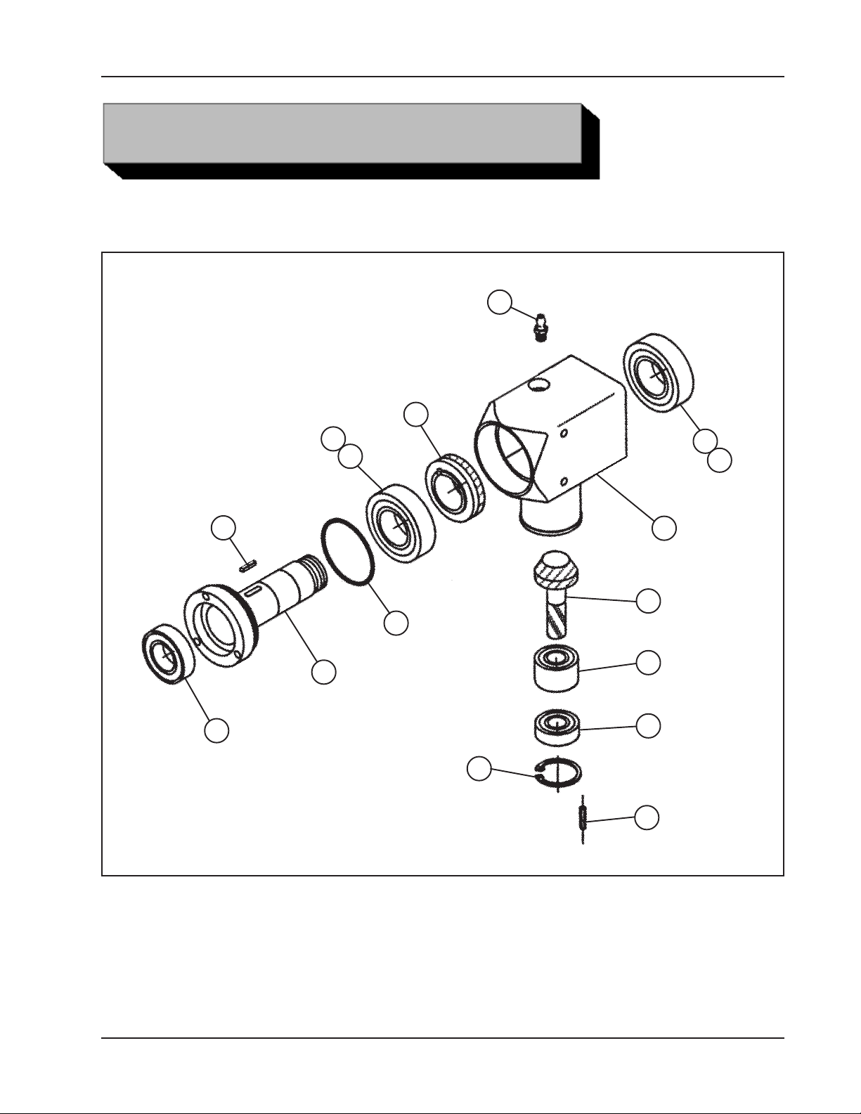
Model 204B BEVELMASTER™
ILLUSTRATED P ARTS BREAKDOWN
MODEL 204B BEVELMASTER™ SUB-ASSEMBLY (P/N 02-2222)
31
28
A
16
8
3
10
9
9
1
27
5
11
7
14
19
10
92-0699 : Rev. 060412
35
Page 36
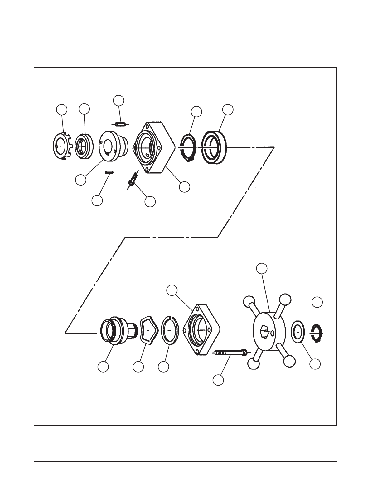
TRI TOOL INC.
MODEL 204B BEVELMASTER™ SUB-ASSEMBLY (P/N 02-2222) Con't
18
A
23
30
24
12
4
6
17
25
29
20
15
26
2
13
22
21
36
92-0699 : Rev. 060412
Page 37

Model 204B BEVELMASTER™
Parts List, Model 204B BEVELMASTER™ Sub-Assembly (P/N 02-2222)
Item Part
No. No. Description Qty
1. 19-0764 HOUSING, MAIN 1
2. 19-0729 HOUSING, FEED 1
3. 20-1025 SHAFT, MAIN 1
4. 27-0513 ADAPTER, FEED 1
5. 28-0248 O-RING 1
6. 29-0005 BEARING, BALL 1
7. 29-0326 BEARING, BALL 1
8. 29-0327 BEARING, BALL 1
9. 29-0328 BEARING, TAPER, CONE 2
10. 29-0329 BEARING, TAPER, CUP 2
11. 29-0345 BEARING, BALL 1
12. 30-0309 RING, RETAINING, EXTERNAL 1
13. 30-0411 RING, RETAINING, EXTERNAL 1
14. 30-2358 RING, RETAINING, INTERNAL 1
15. 30-2359 SHIM 1
16. 31-0103 KEY, SQUARE, ROUND ENDS 1
17. 31-0155 KEY, SQUARE 1
18. 32-0081 PIN, DOWEL, 3/16" DIA X 3/4" 2
19. 32-0493 PIN, DOWEL, 1/8" DIA X 7/8" 1
20. 33-0030 SCREW, CAP, #10-24 X 3/4" 1
21. 33-0047 SCREW, CAP, 1/4-20 X 2 1/4" 4
22. 34-0236 WASHER, THRUST 1
23. 34-0310 WASHER, LOCK 1
24. 35-0443 NUT, LOCK 1
25. 35-0444 NUT, FEED 1
26. 41-0136 HANDLE ASSEMBL Y 1
27. 39-0754 GEAR, BEVEL, PINION 1
28. 39-0755 GEAR, BEVEL 1
29. 40-0227 SPRING, WAVE 1
30. 45-0248 BUSHING, FEED ADAPTER 1
31. 54-0375 FITTING, GREASE 1
92-0699 : Rev. 060412
37
Page 38

TRI TOOL INC.
Parts List, Model 204B BEVELMASTER™ Sub-Assembly (P/N 02-2222) Con't
Item Part
No. No. Description Qty
NOT SHOWN
05-1327 WRENCH KIT, 204B
36-0004 WRENCH, L, 7/64" HEX 1
36-0006 WRENCH, L, 9/64" HEX 1
36-0007 WRENCH, L, 5/32" HEX 1
36-0010 WRENCH, L, 1/4" HEX 1
36-0018 WRENCH, T, 1/8" HEX 1
36-0020 WRENCH, T, 5/32" HEX 1
36-0076 WRENCH, COMBINATION, 9/16" 1
86-0214 CARRYING CASE 1
38
92-0699 : Rev. 060412
Page 39
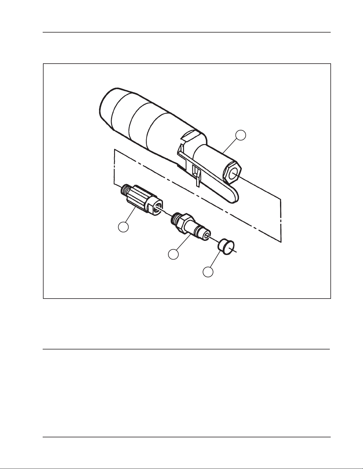
Model 204B BEVELMASTER™
MOTOR ASSEMBLY, AIR (P/N 57-0224)
4
1
2
3
Parts List, Motor Assembly, Air (P/N 57-0224)
Item Part
No. No. Description Qty
1. 53-0046 VALVE, FLOW CONTROL 1
2. 54-0126 COUPLING, MALE QD 1
3. 54-0201 CAP, YELLOW 1
4. 57-0223 MOTOR, INLINE AIR 1
92-0699 : Rev. 060412
39
Page 40
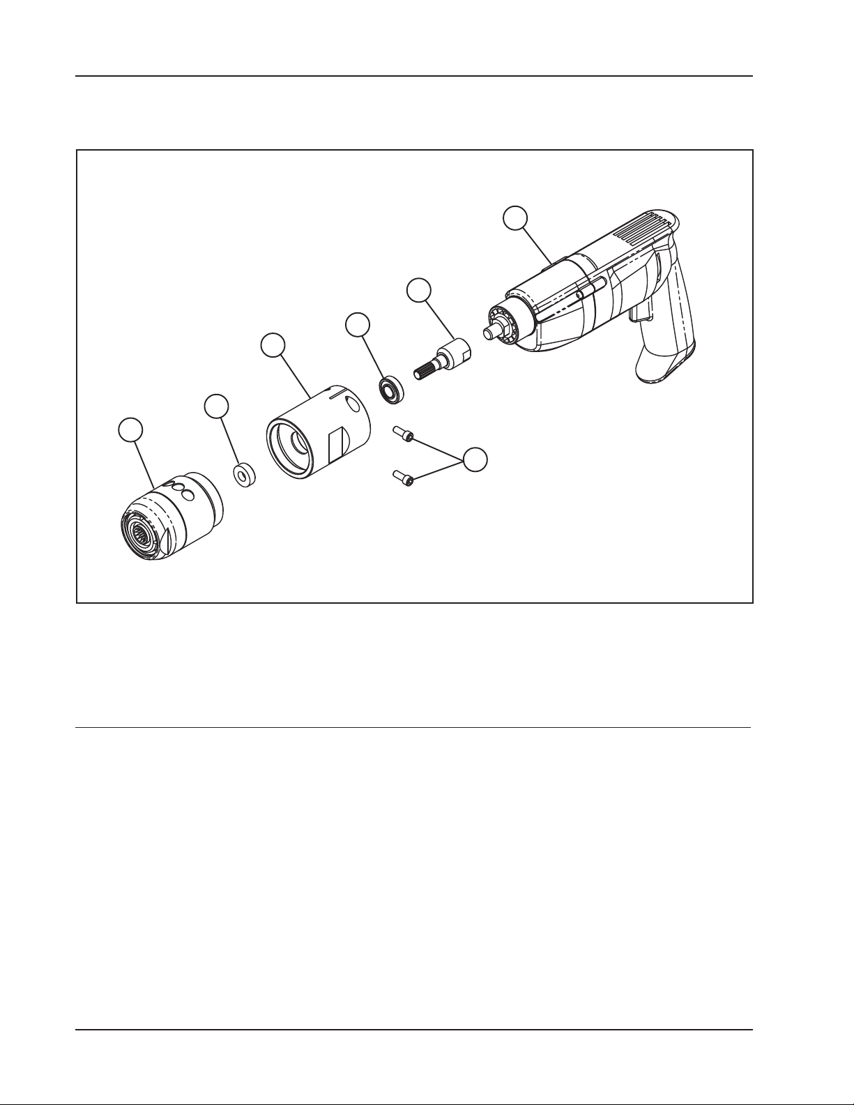
TRI TOOL INC.
5
ELECTRIC MOTOR ASSEMBLY, 220V, 110V
1
3
4
2
7
6
Parts List, Electric Motor Assembly, 220V
Item Part
No. No. Description Qty
58-0133 MOTOR ASSEMBL Y, 220V 1
1. 58-0039 MOTOR, MOD, ELECTRIC, 220V 1
2. 27-0357 ADAPTER, MOTOR 1
3. 39-0568 GEAR, DRIVE 1
4. 29-0182 BEARING, BALL, 1/2" X 1 1/8" X 3/8" 1
5. 91-0545 GEAR ASSEMBL Y 1
6. 33-0039 SCREW, CAP, 1/4-20 X 5/8" 2
7. 44-0441 SPACER 1
40
92-0699 : Rev. 060412
Page 41

Model 204B BEVELMASTER™
Parts List, Electric Motor Assembly, 110V
Item Part
No. No. Description Qty
58-0147 MOTOR ASSEMBL Y, 1 10V 1
1. 58-0038 MOTOR, MOD, ELECTRIC, 110V 1
2. 27-0357 ADAPTER, MOTOR 1
3. 39-0568 GEAR, DRIVE 1
4. 29-0182 BEARING, BALL, 1/2" X 1 1/8" X 3/8" 1
5. 91-0545 GEAR ASSEMBL Y 1
6. 33-0039 SCREW, CAP, 1/4-20 X 5/8" 2
7. 44-0441 SPACER 1
92-0699 : Rev. 060412
41
Page 42
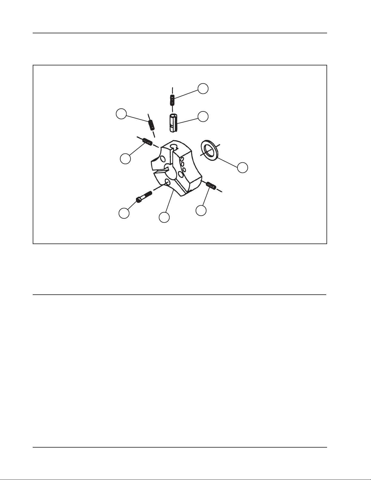
TRI TOOL INC.
CUTTING HEAD KIT, 4" DIA (P/N 03-0049)
4
6
7
3
1
8
2
5
Parts List, Cutting Head Kit, 4" DIA (P/N 03-0049)
Item Part
No. No. Description Qty
1. 21-0475 HEAD, 4.0" DIA 1
2. 28-0249 SEAL, OIL 1
3. 33-0057 SCREW, CAP, 5/16-18 X 1 1/4" 3
4. 33-0514 SCREW, SET, 5/16-18 X 3/8", CUP PT 1
5. 33-0517 SCREW, SET, 5/16-18 X 5/8", CUP PT 6
6. 33-0518 SCREW, SET, 5/16-18 X 3/4", CUP PT 3
7. 33-0996 SCREW, SET, 5/16-18 X 1/2", HDOG 1
8. 62-0104 CAM, FACING BIT 1
42
92-0699 : Rev. 060412
Page 43
Model 204B BEVELMASTER™
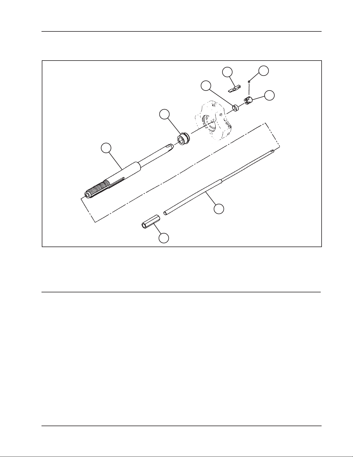
MANDREL ASSEMBLY (P/N 06-0413)
8
6
7
1
2
4
3
5
Parts List, Mandrel Assembly (P/N 06-0413)
Item Part
No. No. Description Qty
1. 13-0429 MANDREL 1
2. 23-0298 ROD, DRAW 1
3. 24-1463 PLATE, BUTT #1 1
24-1464 PLATE, BUTT #2 1
4. 33-0477 SCREW, SET, #8-32 X 3/16", CUP PT 1
33-0478 SCREW, SET, #8-32 X 1/4", CUP PT 1
5. 35-0523 NUT, DRAW ROD, 3/8-16 1
6. 40-0130 SPRING, FLAT 1
40-0136 SPRING, FLAT 1
7. 46-0437 SLEEVE, MANDREL 1
8. 48-0596 BLOCK, RAMP #1 3
48-0597 BLOCK, RAMP #2 3
92-0699 : Rev. 060412
43
Page 44
TRI TOOL INC.
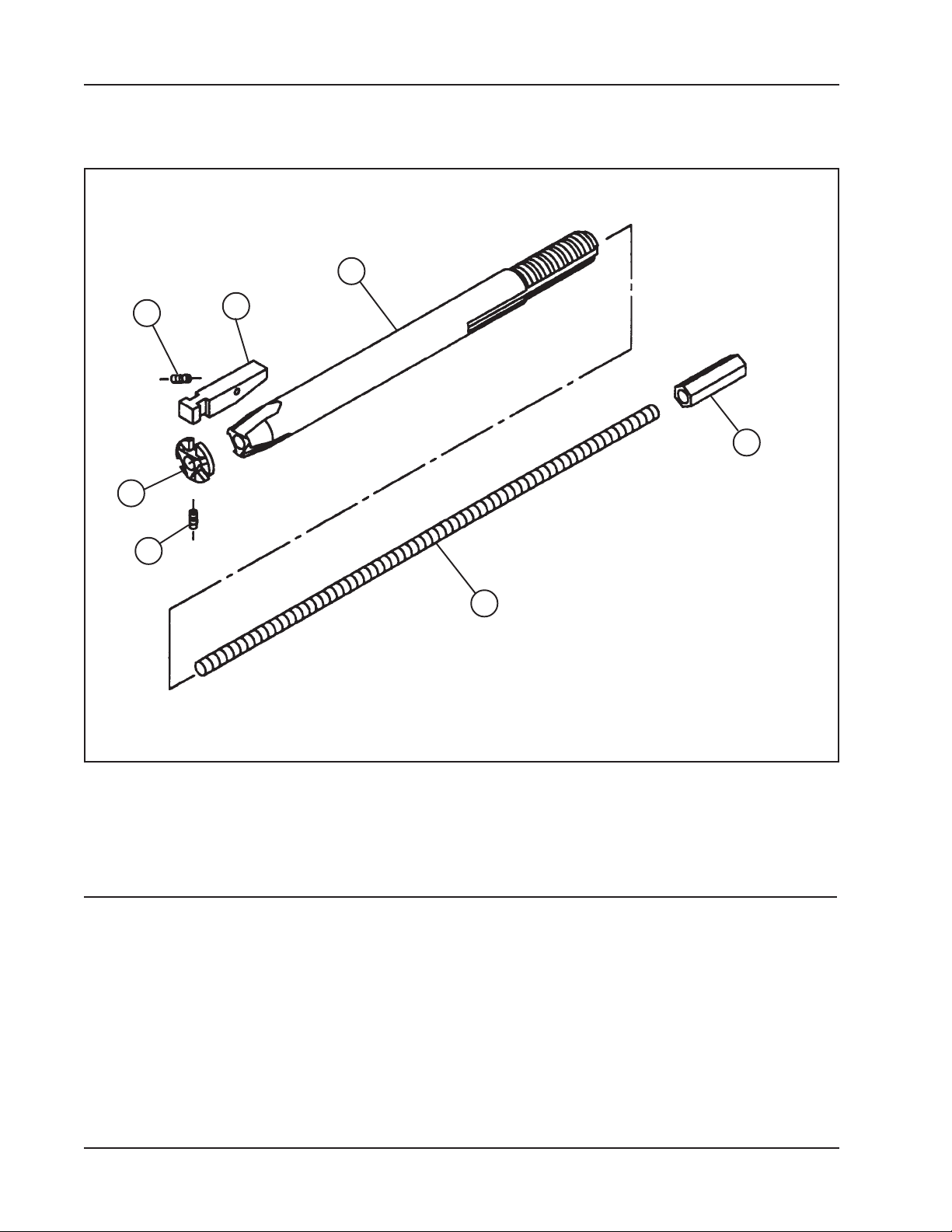
MANDREL ASSEMBLY (P/N 06-0414)
1
6
3
4
7
5
2
Parts List, Mandrel Assembly (P/N 06-0414)
Item Part
No. No. Description Qty
1. 13-0426 MANDREL 1
2. 23-0297 ROD, DRAW 1
3. 24-1462 PLATE, BUTT 1
4. 33-0489 SCREW, SET, #10-24 X 5/16", CUP PT 1
5. 35-0523 NUT, DRAW ROD, 3/8-16 1
6. 40-0108 SPRING, EXTENSION 1
7. 48-0976 BLOCK, RAMP 3
44
92-0699 : Rev. 060412
Page 45
Model 204B BEVELMASTER™
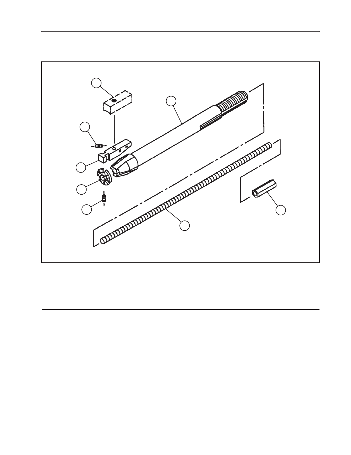
MANDREL ASSEMBLY (P/N 06-0419)
1
2
7
8
4
5
3
6
Parts List, Mandrel Assembly (P/N 06-0419)
Item Part
No. No. Description Qty
1. 08-XXXX BLOCK, JAW (Ref. the ‘Jaw Blocks’ section.) REF
2. 13-0424 MANDREL 1
3. 23-0295 ROD, DRAW 1
4. 24-1384 PLATE, BUTT 1
5. 33-0490 SCREW, SET, #10-24 X 3/8", CUP PT 1
6. 35-0523 NUT, DRAW ROD, 3/8-16 1
7. 40-0001 SPRING, EXTENSION 5
8. 48-0964 BLOCK, RAMP, #1 3
48-0965 BLOCK, RAMP, #2 3
48-0966 BLOCK, RAMP, #3 3
92-0699 : Rev. 060412
45
 Loading...